|
|
|
|
|
|
Official building time: 2224.3 hours.
|
|
|
Building time for Finish: 86.0 hours.
Number of records for Finish: 38. |
|
2014-01-18 |
Hours: 5 |
Category:
Finish
|
|
Manual Ref:
|
ID#:
1195
|
|
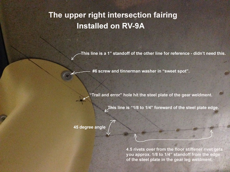
Installed upper and lower main gear intersection fairings |
|
Installed the RVBits upper and lower main gear intersection fairings. The lower ones were easy to locate and drill. The upper one fit nicely but finding places to drill for screws is limited. I used trail and error to find the hole under the foreward bottom skin. Missed by just 1/8" on my first try drilling and hit the steel plate that is on the gear leg weldment. Then figured a way to calculate and draw a line on the bottom skin that was approx. 1/4" forward of the edge of the steel plate on the gear leg weldment. It is a line four and a half rivets outboard of the floor stiffener rivet along the span wise row of rivets in the bottom skin and foreword center section flange. I drew a line 45 degrees off that line and this approximates a line about 1/4" forward and parallel to the fore edge of the steel plate on the gear leg weldment. With the intersection fairing held in place, the "sweet spot" for drilling is apparent. The other two screws were, one in the wing root fairing and one aft of the center section under the outboard seat bay. Had to use a rivnut there. I used #6 screws with tinnerman washers for my intersection fairings.
|
|
|
2012-05-24 |
Hours: 15 |
Category:
Finish
|
|
Manual Ref:
|
ID#:
1178
|
|
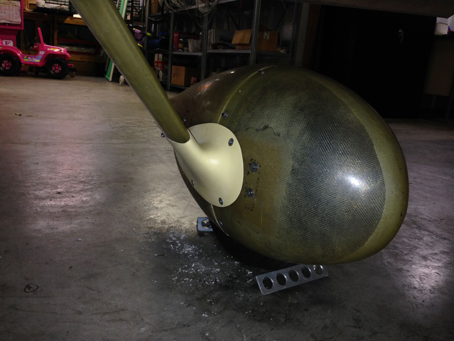
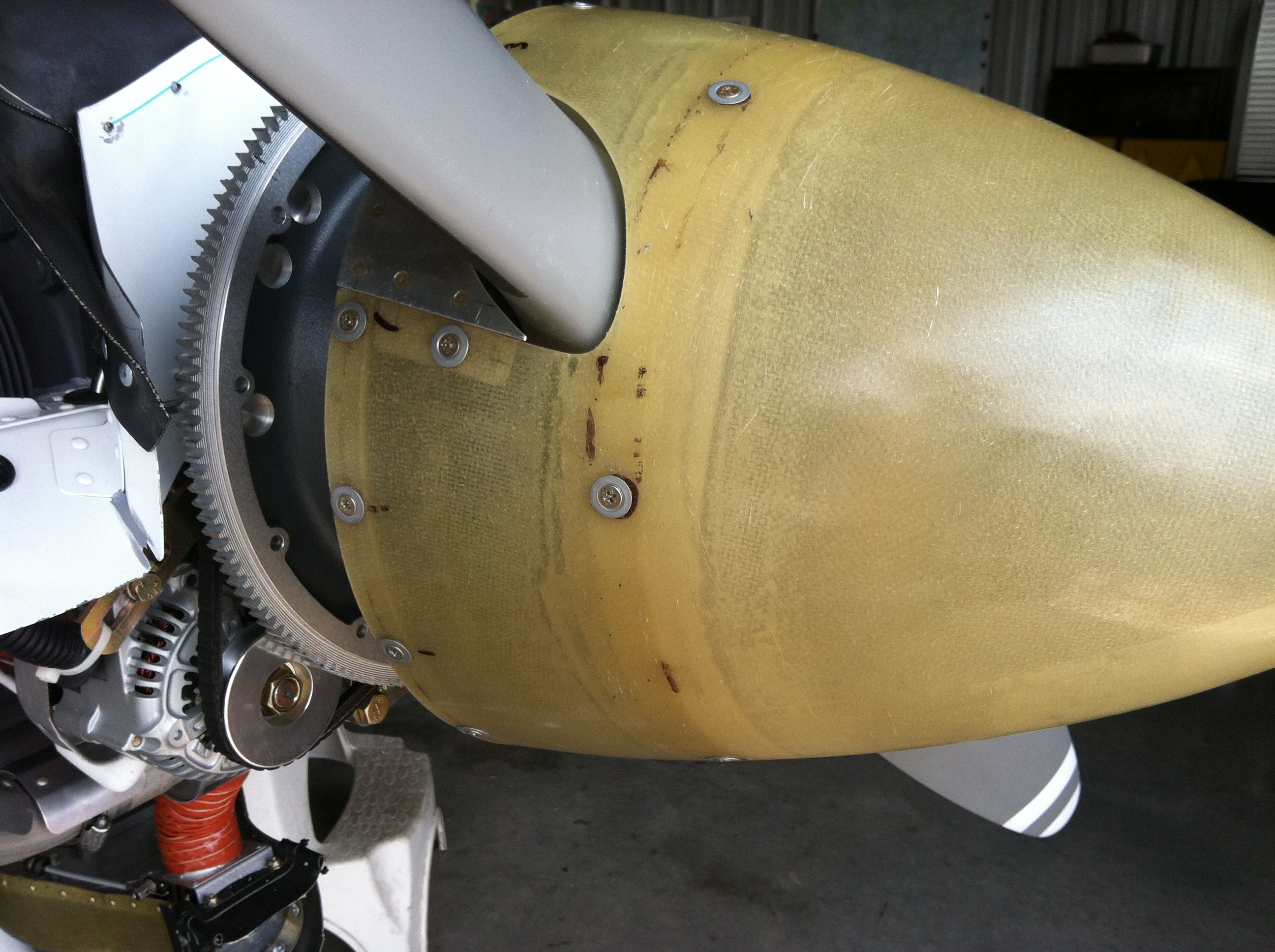
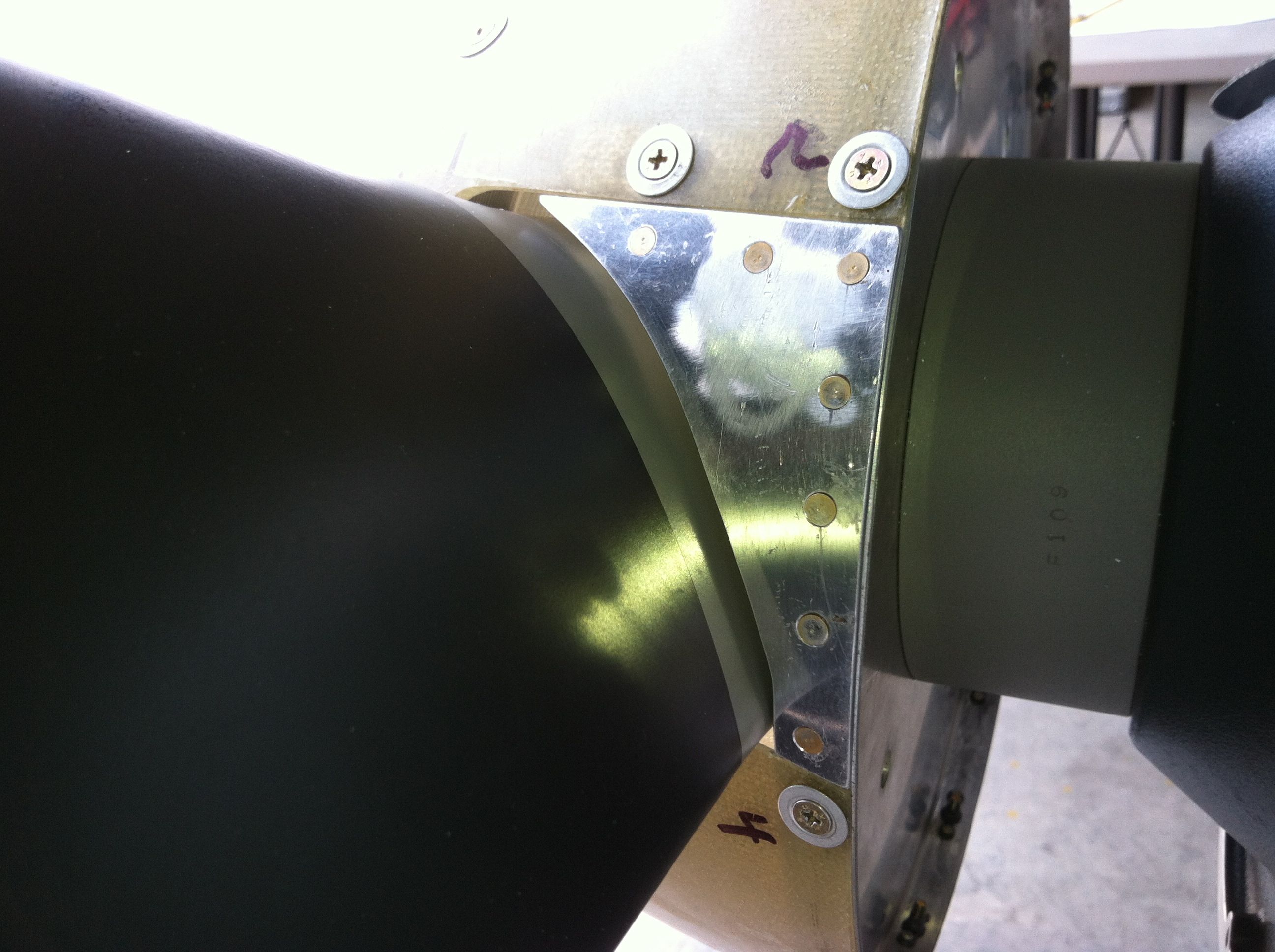
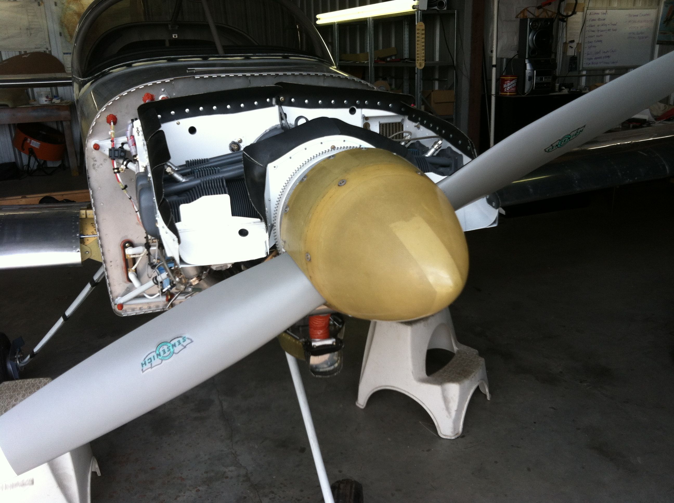
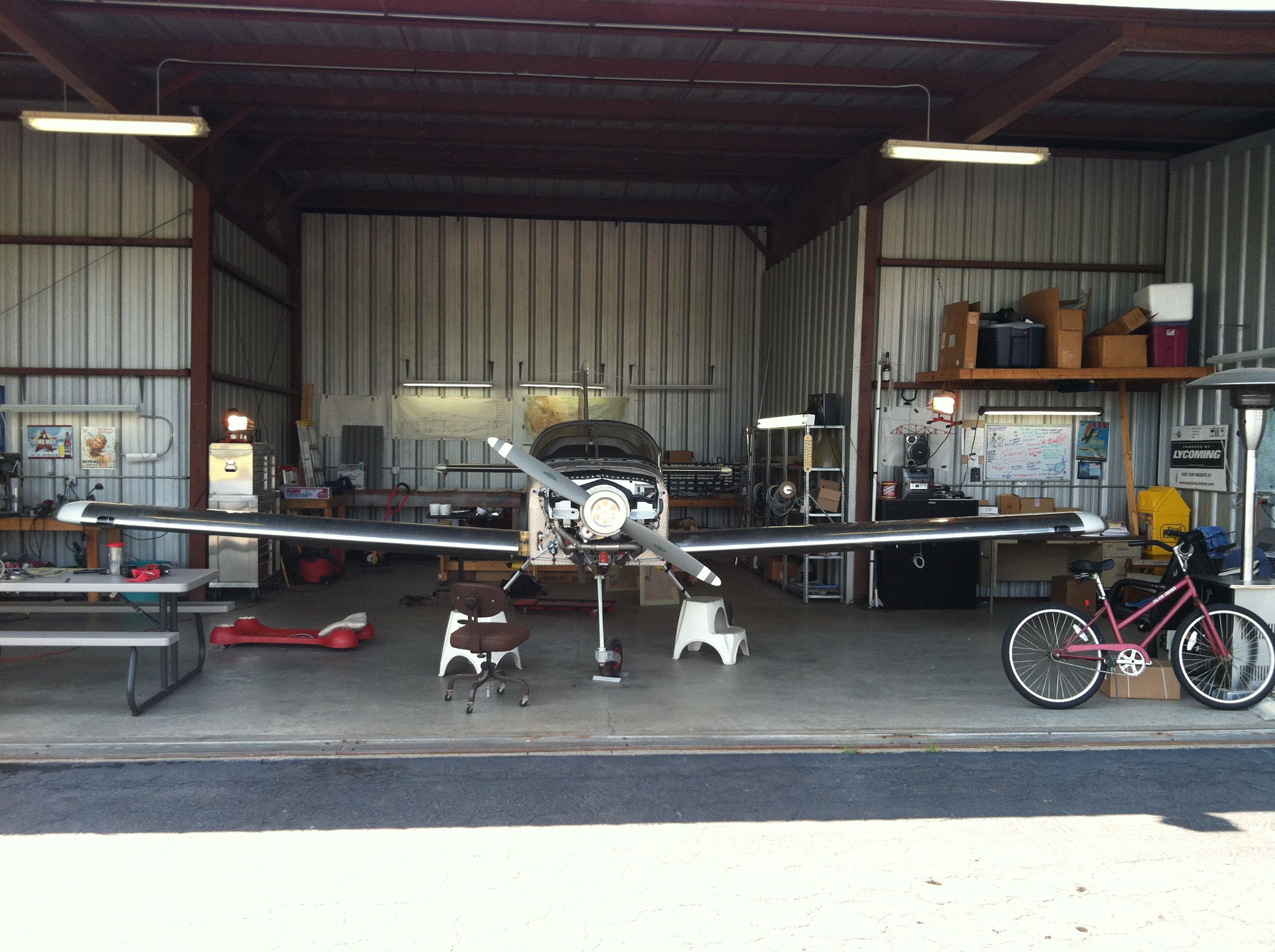
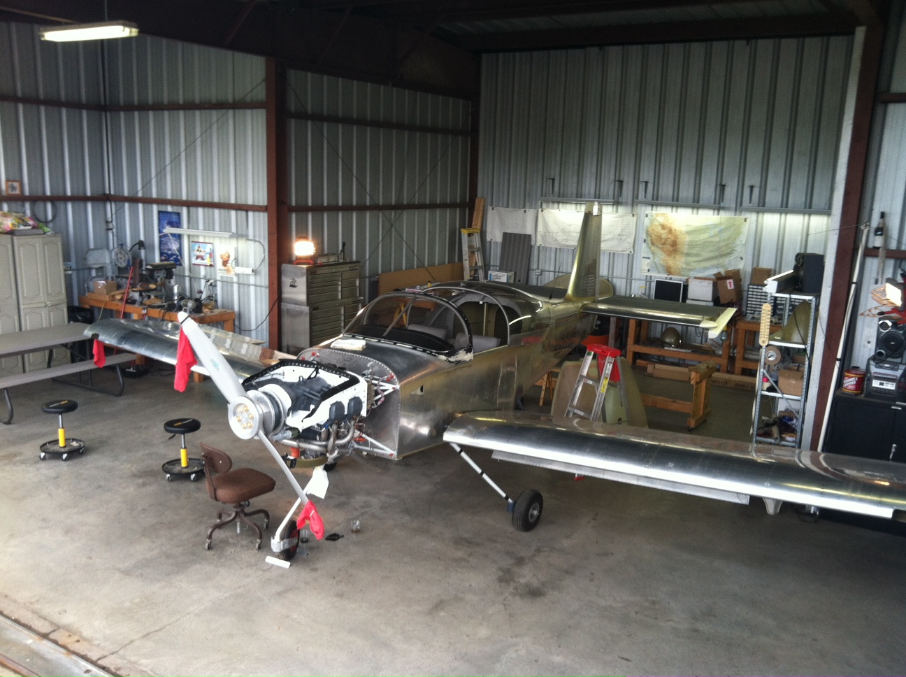
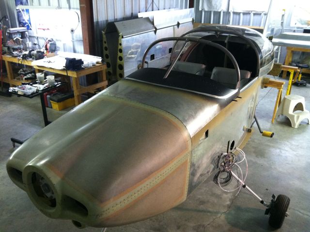
Installed the prop spinner over a period of several days. I started with marking the pattern on the spinner, cutting it until I got the spinner into the position I wanted. Then drilled, countersunk the spinner for the tinnerman washers and screws. I had to add several layers of fiberglass at the front spinner bulkhead to get the spinner to fit nicely. Lots of sanding! For the final fit at the front bulkhead, I waxed the spinner bulkhead flange with mold release then put a bead of epoxy mixed with half flox and half micro balloons, placed the spinner back on and let it sit up for a couple of hours. I removed spinner before the epoxy cured - it had the consistency of a vinyl. It will difficult still to remove the spinner as the epoxy had oozed beyond the edge of the spinner flange in most places. I loosened it by banging the nose with a rubber mallet. Then I made and installed the filler two filler plates. Seems like I may have some slight wobble, but we shall see when I crank the engine exactly how much.
|
|
|
2012-04-29 |
Hours: 4 |
Category:
Finish
|
|
Manual Ref:
|
ID#:
1179
|
|
Crank plug work and installed prop |
|
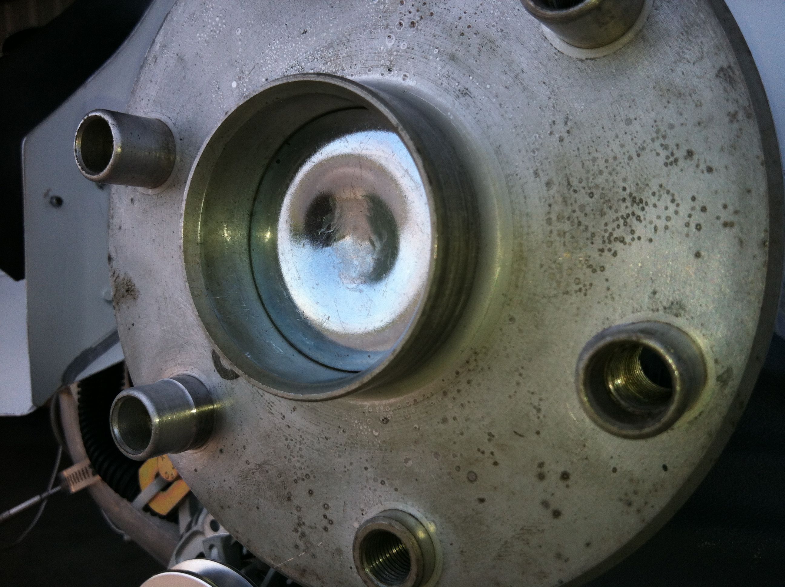
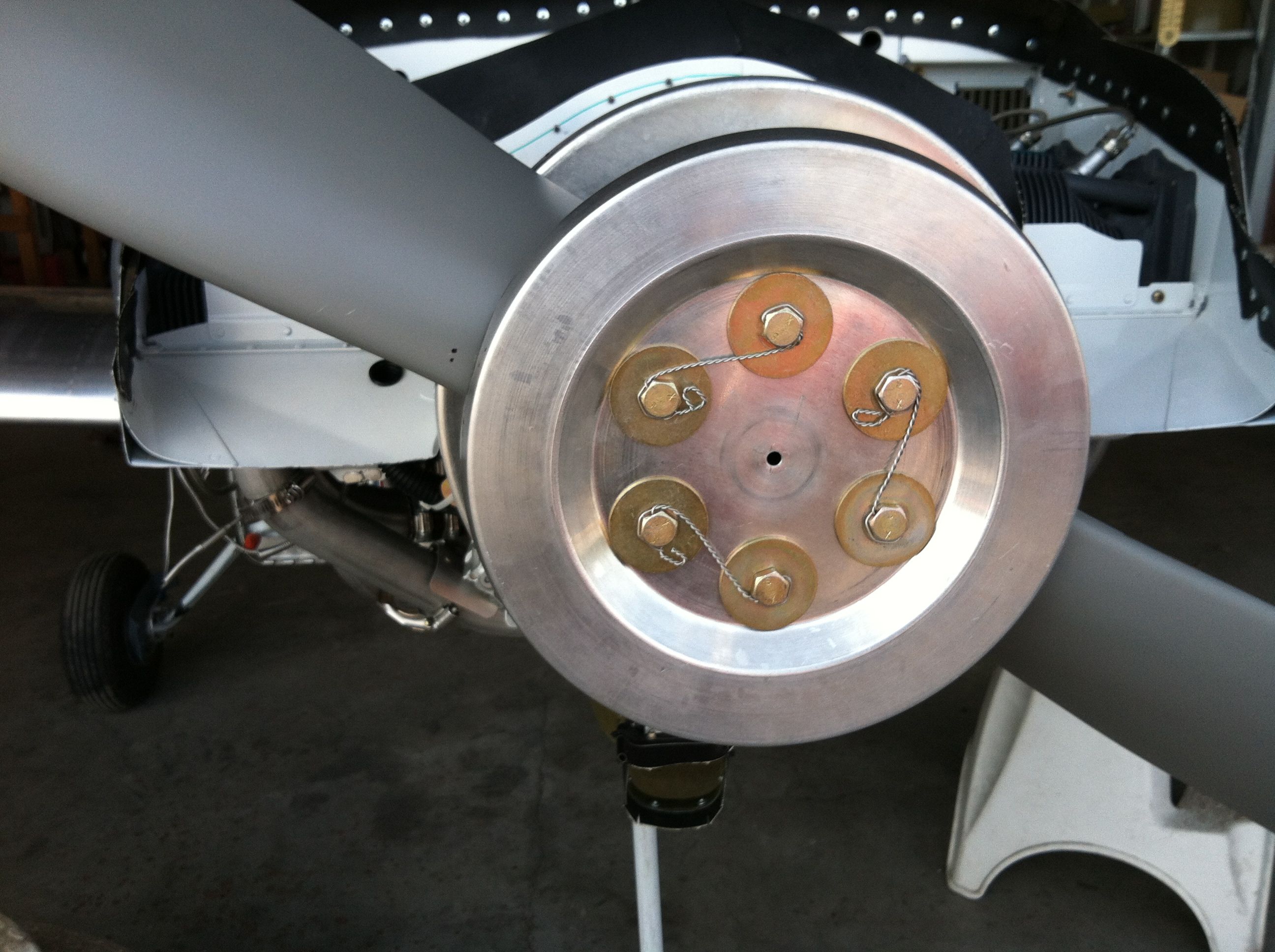
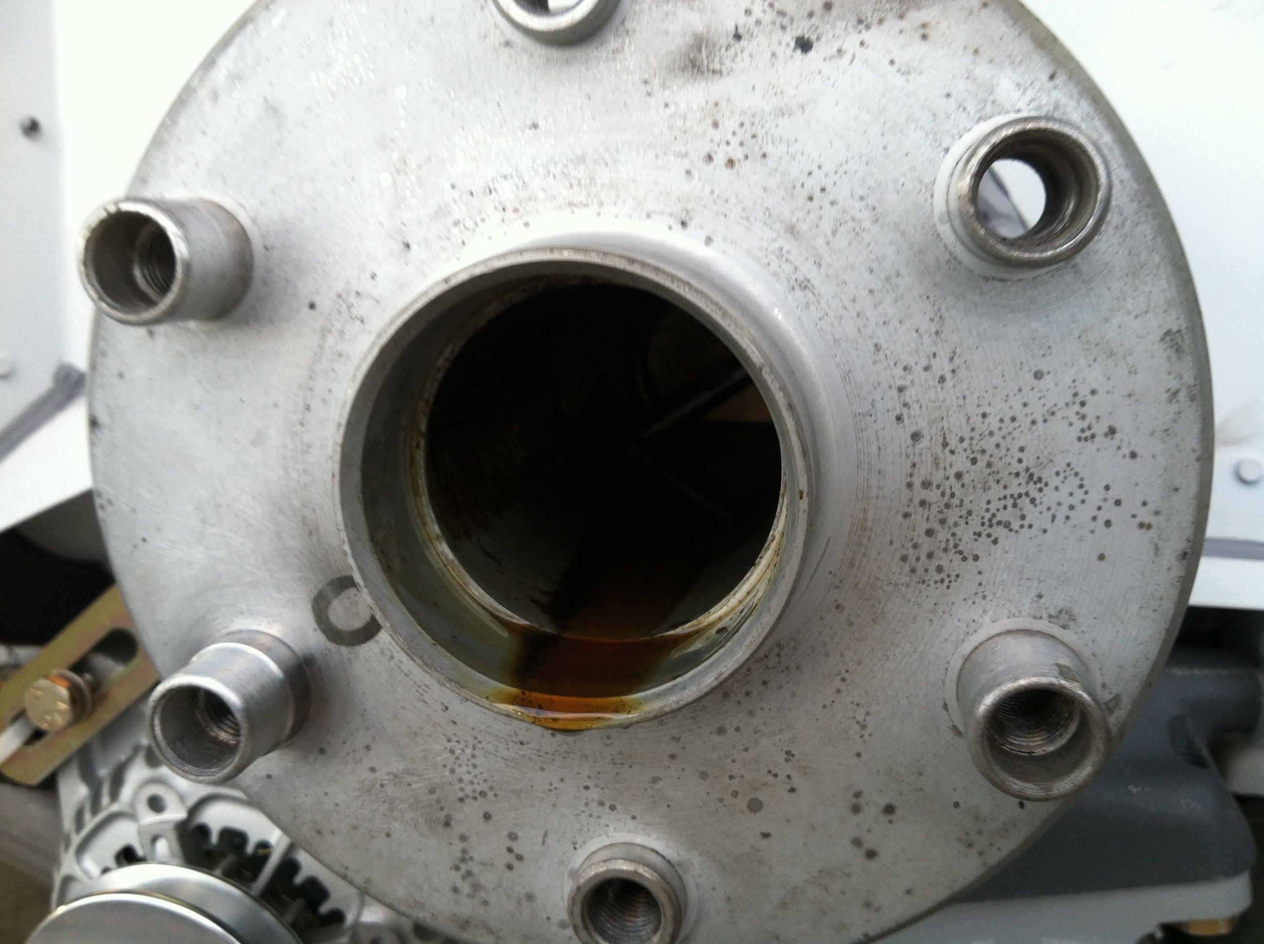
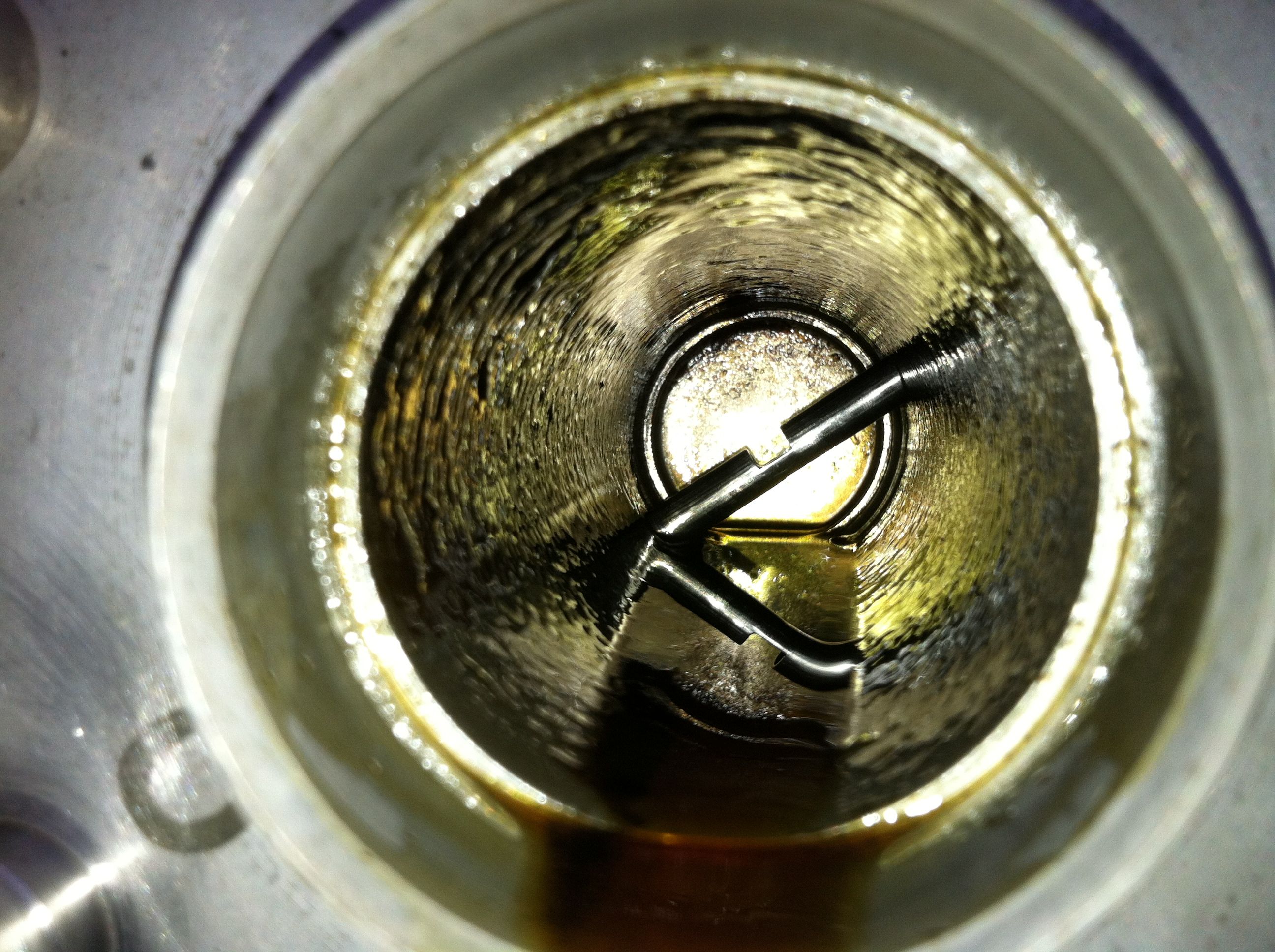
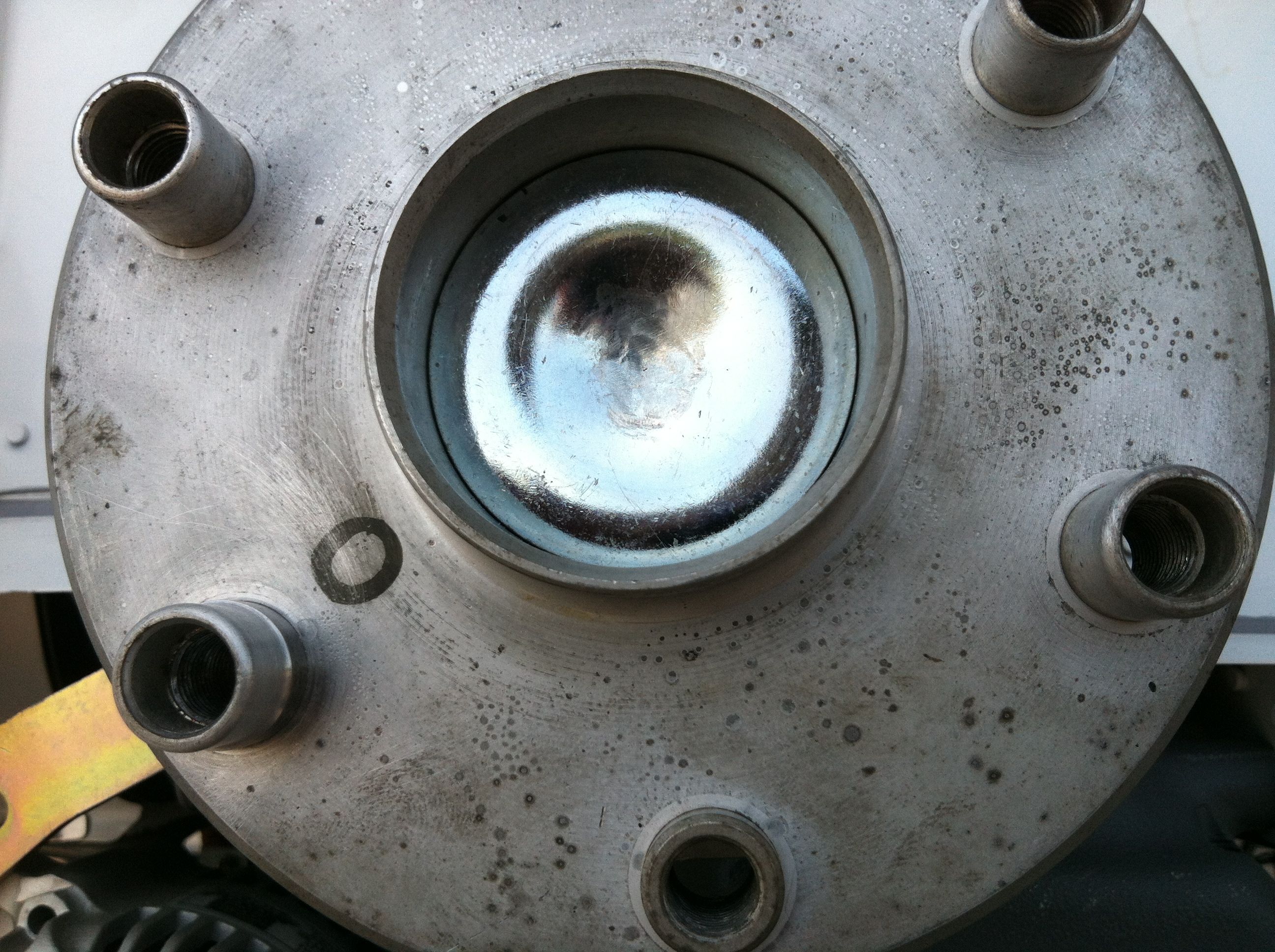
I had to removed the front plug in the crank, and remove the inner plug and replace the front plug with a new one. I really didn't want to have to do this but I Lycoming's Service Instruction 1435 explains this needs to be done to convert from CS to FP. Then engine came with the oil return line and cover plate installed at the rear of the engine. Several folks said it would be fine as is, but to be sure, I called Lycoming and Vans. Both insisted I would need to do the Service Instruction 1435 procedure. So I did. I opted to removed the inner plug altogether versus just piercing a big hole in it as was an option. After removing the inner plug with a slide hammer, I reinstalled a new front plug. Hope it doesn't leak! Then I installed the prop and torqued and safety wired the bolts.
|
|
|
2012-04-25 |
Hours: 1 |
Category:
Finish
|
|
Manual Ref:
|
ID#:
1180
|
|
Removed the crank plug according to Lycoming Service Instruction 1435 |
|
After reading through the Lycoming engine manual I discovered their Service Instruction 1435 that said I would need to removed the front crank plug, pierce or remove the inner plug and replace the front plug with a new STD-1211 plug. I called to make sure because the oil return line is in place and the engine has the proper cover plate installed where the prop governor would be install for the constant speed prop configuration. I called Vans as well. They both insisted that since I have a fixed pitch prop that I need to indeed remove or pierce that inner plug in the crank. So I popped the front one out by piercing a hole in it with a hammer and screw driver. I decided to just remove the inner plug altogether. I used a slide hammer and it came loose easily. Getting it out past the cross bar was a little tricky, but it can be done. I then put a new STD-1211 plug in the front of the crank, with the concave profile facing forward, put a ball peen hammer against it and smacked it several times with an 8# hammer. Hope it doesn't leak.
|
|
|
2012-04-22 |
Hours: 3 |
Category:
Finish
|
Helper: Multiple
|
Manual Ref:
|
ID#:
1177
|
|
Installed the wings for what I think will be the last time. Thanks to Rick, Tom and Don for the help. It is great to see them on again. Getting the right wing into the center spar was tough. The left one slid right in much easier. The bolts were tough to install. I had to use a combination of tapping them with a hammer, flush set on the rivet gun to get them in. NOTE: the bottom two large bolts on each side need to go in just a little, then add the nut and tighten and push the bolt in a little at a time to avoid hitting the gear leg weldments. I'll have back mine out since I hammmered them all the way home. Ugh.
|
|
|
2012-03-11 |
Hours: 3.5 |
Category:
Finish
|
|
Manual Ref:
|
ID#:
1176
|
|
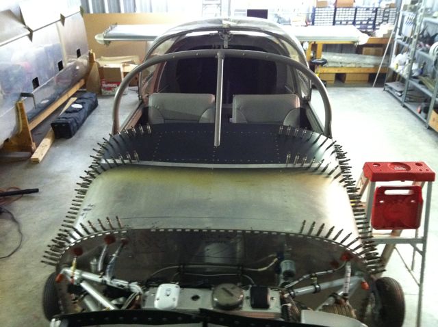
Windscreen fiberglass work |
|
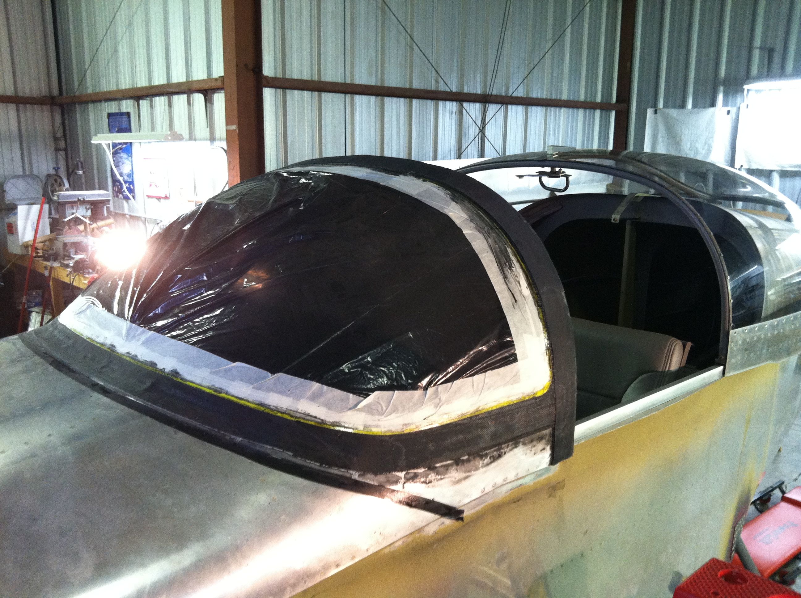
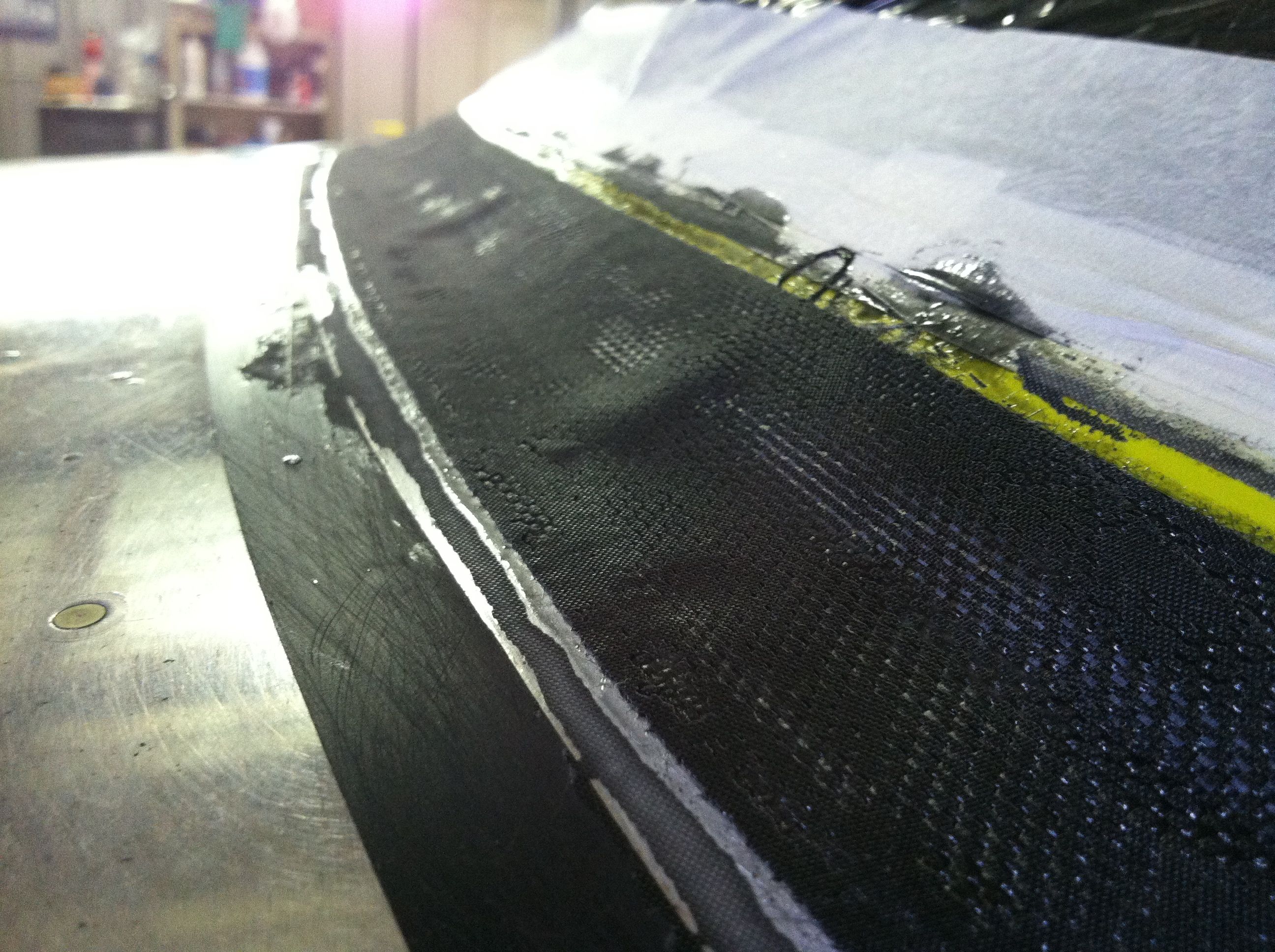
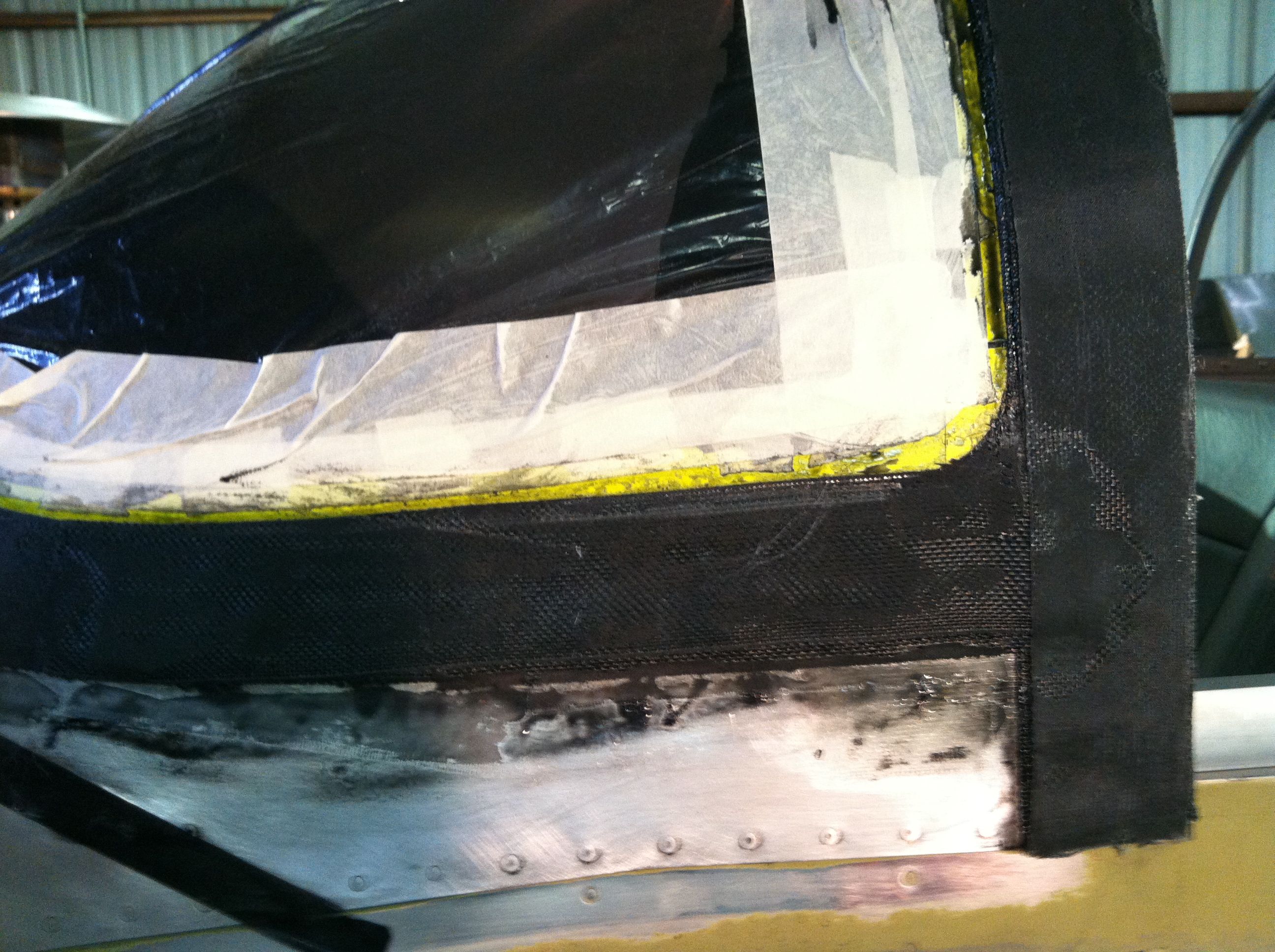
Finally got everything all prepped for laying fiberglass strips around the windscreen. Double and triple checked a few times to make sure I would not glue my slider canopy to the windscreen permanently. I started by mixing "single serving" doses of epoxy with the black dye. I painted around the entire perimeter of the windscreen where the fiberglass would be laid up on the windscreen with the black epoxy. I started laying 2" strips across the top and down the sides. I laid up four layers across the top and down the sides initially, then began laying up around the front to the sides, overlapping where they met aftward at the rollbar. I laid up all seven of the progressing layers around the windscreen/forward skin, starting with the 1/2", then progressing at 1/4" each time to end up with the final 2" layer. I had to cut the strips and overlap them each layer to get them to lay down nicely, shaping each layer with my fingers. After getting the seven-layer progression done around the windscreen/top skin, I put another two layers across the top to end up with six layers there.
|
|
|
2012-03-04 |
Hours: 3 |
Category:
Finish
|
|
Manual Ref:
|
ID#:
1175
|
|
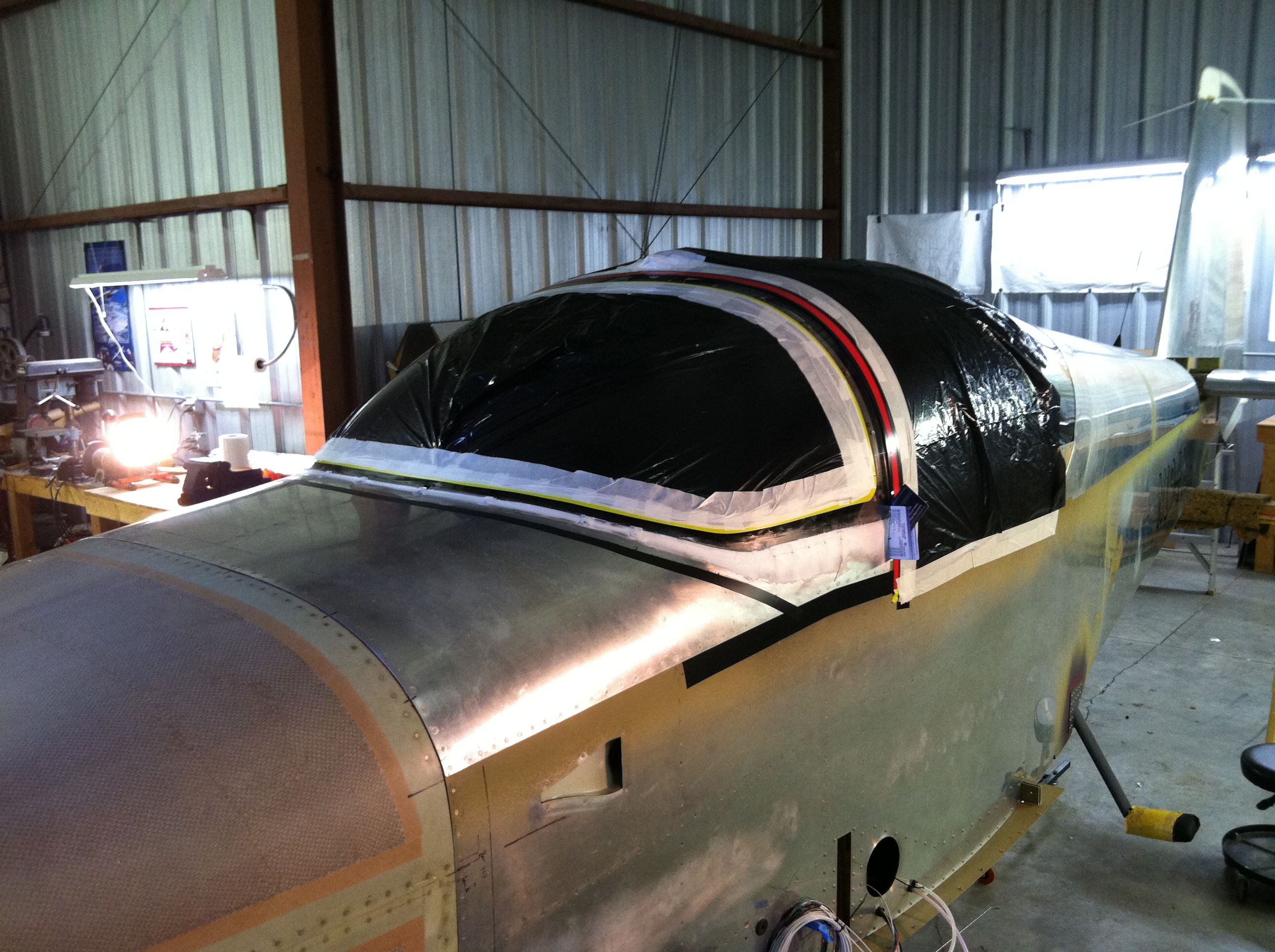
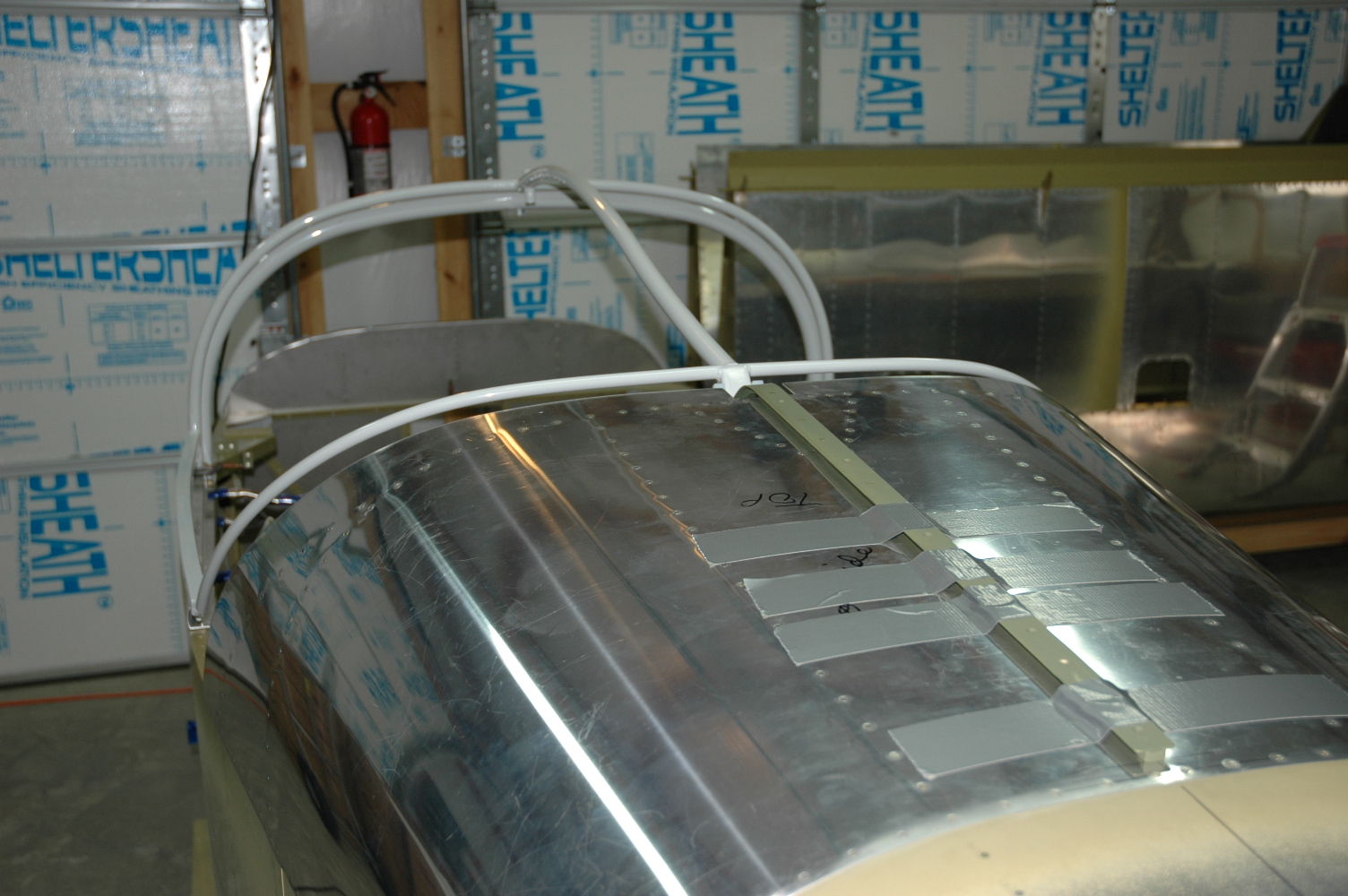
Almost ready to glass the windscreen |
|
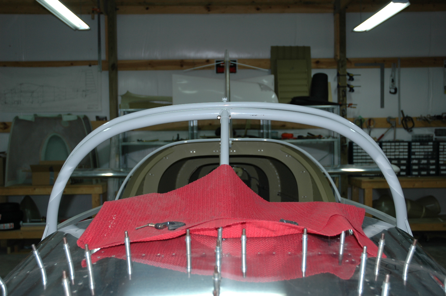
Did more prep work around the windscreen to get closer to fiberglassing the windscreen. I had to put a lot of filler along the lower sides to fill the deep gaps and try and cover the anchor clip rivets. Also cover the windscreen and canopy with plastic to protect it from stray epoxy. Some sanding and perhaps one more session with micro balloons and I should be ready to lay up the fiberglass.
|
|
|
2012-02-26 |
Hours: 2 |
Category:
Finish
|
|
Manual Ref:
|
ID#:
1174
|
|
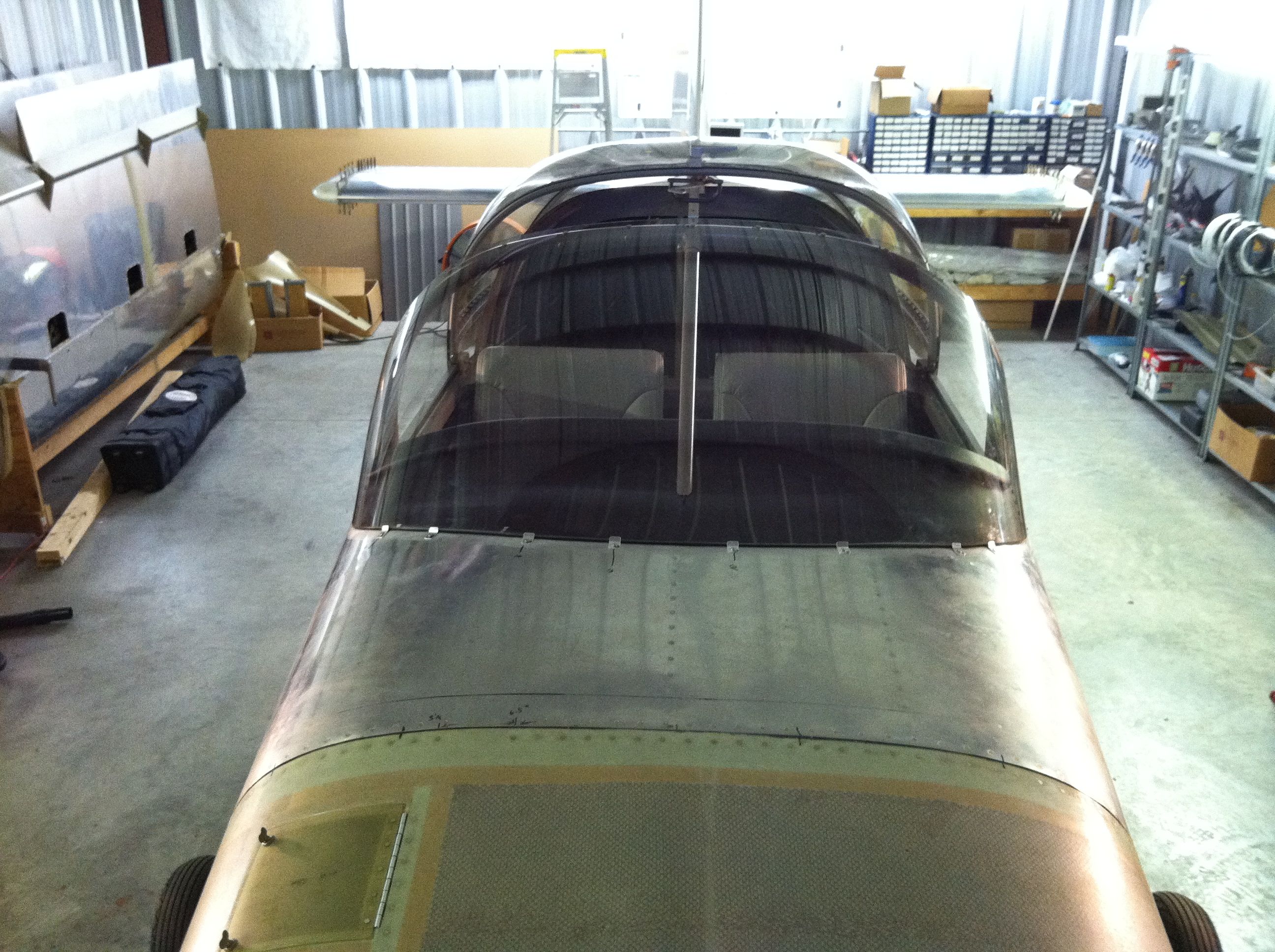
Windscreen anchor clips done |
|
I finished installing all the windscreen anchor clips across the front of the windscreen. I heated the windscreen again nice and hot with my patio heaters. It got pretty darn hot. I expect a good bit of stress in the windscreen has been relieved. Next up, fiberglass!
|
|
|
2012-02-25 |
Hours: 2.5 |
Category:
Finish
|
|
Manual Ref:
|
ID#:
1173
|
|
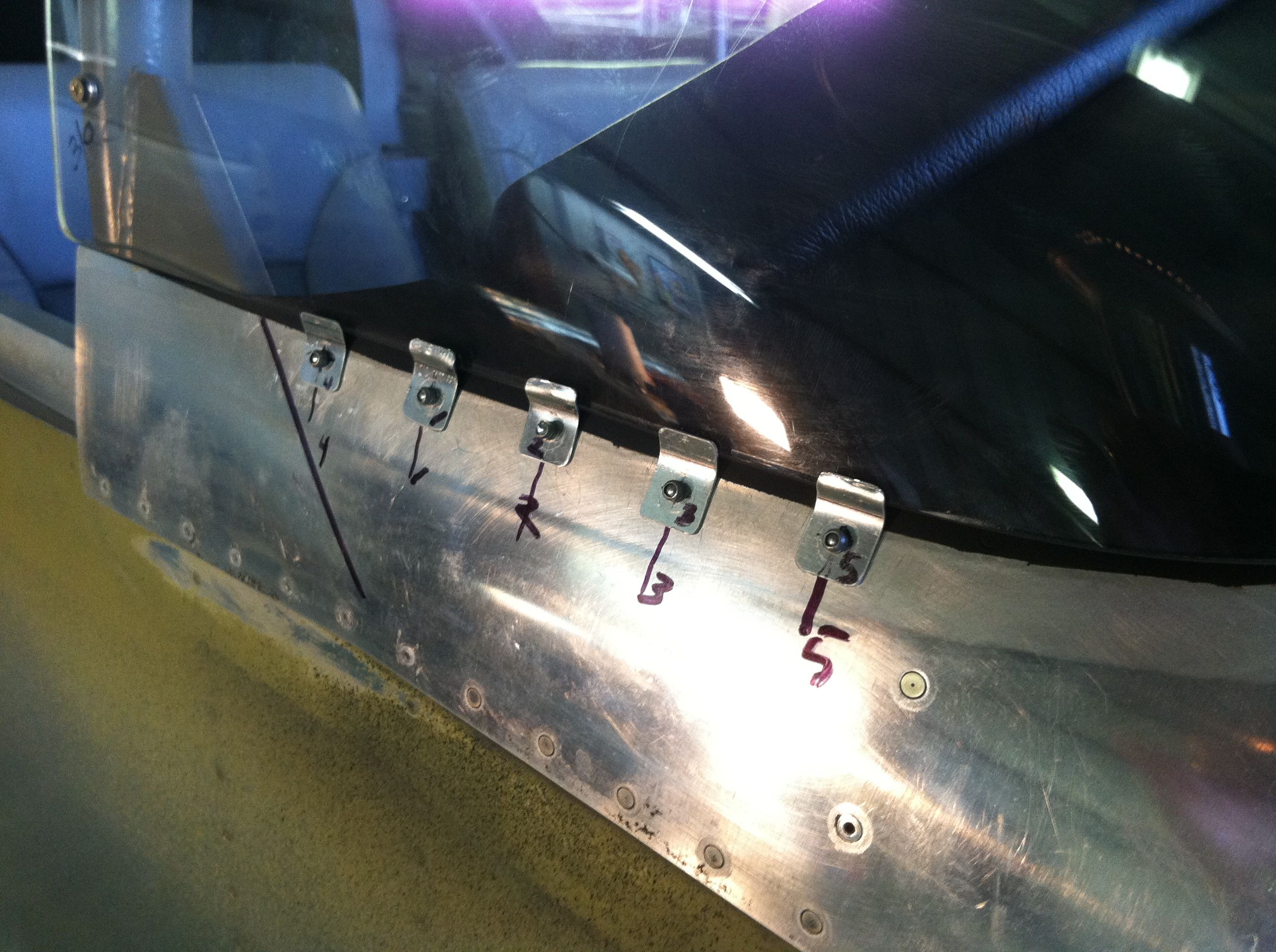
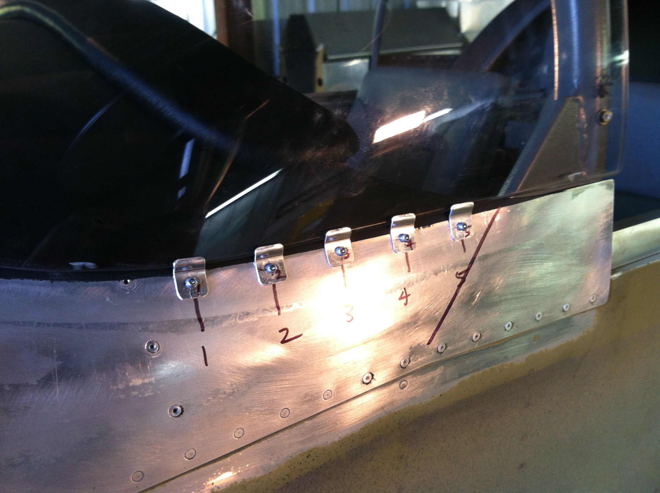
Attached side clips on the windscreen |
|
My good friend Steve "volunteered" to help me install the clips on the windscreen along the sides. I could have cut the windscreen lower and avoided having to use so many. It took a lot of pressure to push the sides of the windscreen in so I used five clips on each side to spread the load. I used my patio heaters to heat the windscreen up nice and hot for a couple of hours to help relieve stress in the windscreen.
|
|
|
2012-02-02 |
Hours: 5 |
Category:
Finish
|
Helper: Pam
|
Manual Ref:
|
ID#:
1172
|
|
Riveted the top forward skin |
|
Pam helped me rivet the top forward skin on. After a few sessions, we finished all but for rivets that are hard to get to, so I will use a pulled rivet in those places.
|
|
|
2009-09-07 |
Hours: 3 |
Category:
Finish
|
|
Manual Ref:
|
ID#:
1019
|
|
Disassembled the canopy and prepped for paint |
|
Disassembled the slider canopy and prepped everything for painting. I primed the slider canopy frame and cleaned all the sheet metal parts. They are ready for priming. Today is my builder number day - 90709 - and I am not finished with my project. I always jokes that I hope I would be finished before my builder number became the date. Oh well!
|
|
|
2009-01-17 |
Hours: 1 |
Category:
Finish
|
|
Manual Ref:
|
ID#:
975
|
|
Hopefully a solution for the nose gear bolt |
|
I have been reading on Vansairforce.net about the nose gear bolt rotating and what others have done. The thread is HERE. The problem starts when you drill out the nose gear hole. If you do not have a 0.311 drill, then Vans says 5/16 is okay. Then the bolt is not snug enough and might allow slight movement that will eventually cause the gear bolt holes in the engine mount to become elongate. Some folks have reamed to a larger size used a close tolerance bolt. Since I am still building I have decided to order a close tolerance bolt (NAS6605-26) to replace the original AN5-20A bolt. The AN5-20A slides into the mount/gear leg with little resistance, and I am told that it should be "tap-in" tight so there is not chance for movement. We'll see how it works out when I received my bolts. Also ordered two NAS6605-29 bolts so I will have them if I decided to replace the main gear leg bolts. Conclusion: I do not think you should drill the nose gear holes with a 5/16 drill. If you do, you will need a close tolerance or oversized bolt.
|
|
|
2009-01-05 |
Hours: 1 |
Category:
Finish
|
|
Manual Ref:
|
ID#:
974
|
|
Removed nose gear and engine mount |
|
I removed the nose gear and engine mount so that I could finally prime the two spacer washers used between the firewall and the engine mount at the bottom inner two engine mount bolt holes. Also, I will need to enlarge the hole in the firewall that is for accessing the nose gear mount bolt. It's original location is about 1/2" too low. I am pretty sure I located it per plans, so my pretty round hole will become elongated. Not sure how I will cover this once done.
|
|
|
2008-11-07 |
Hours: 0 |
Category:
Finish
|
Helper: Pam
|
Manual Ref:
|
ID#:
973
|
|
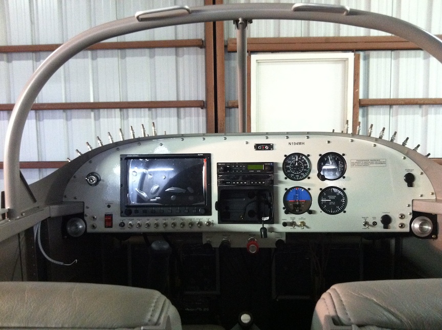
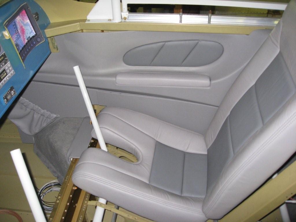
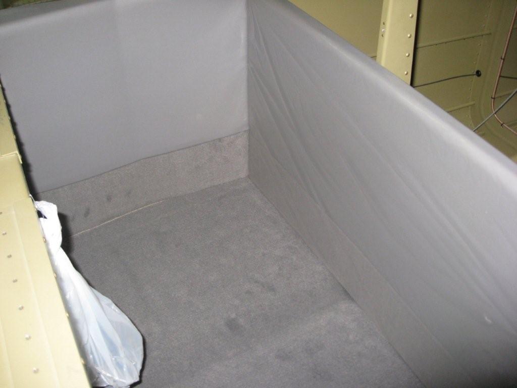
Interior arrived from Classic Aero |
|
My early Christmas! My interior package arrived from Classic Aero yesterday. Pam and I got a chance today to test fit some pieces to see how it will look. Nice! I ended up getting the Aviator panel package, carpet package and had already gotten the leather Sport seats a while back.
|
|
|
2007-07-11 |
Hours: 1.5 |
Category:
Finish
|
|
Manual Ref:
9-10
|
ID#:
955
|
|
Trudging further with the slider canopy frame |
|
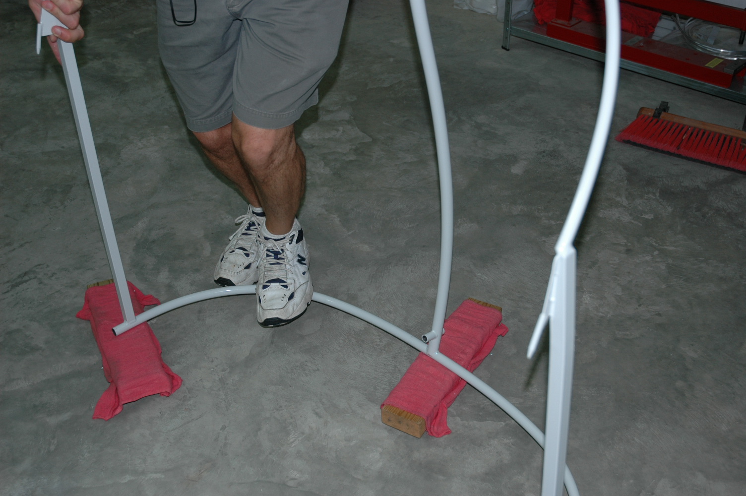
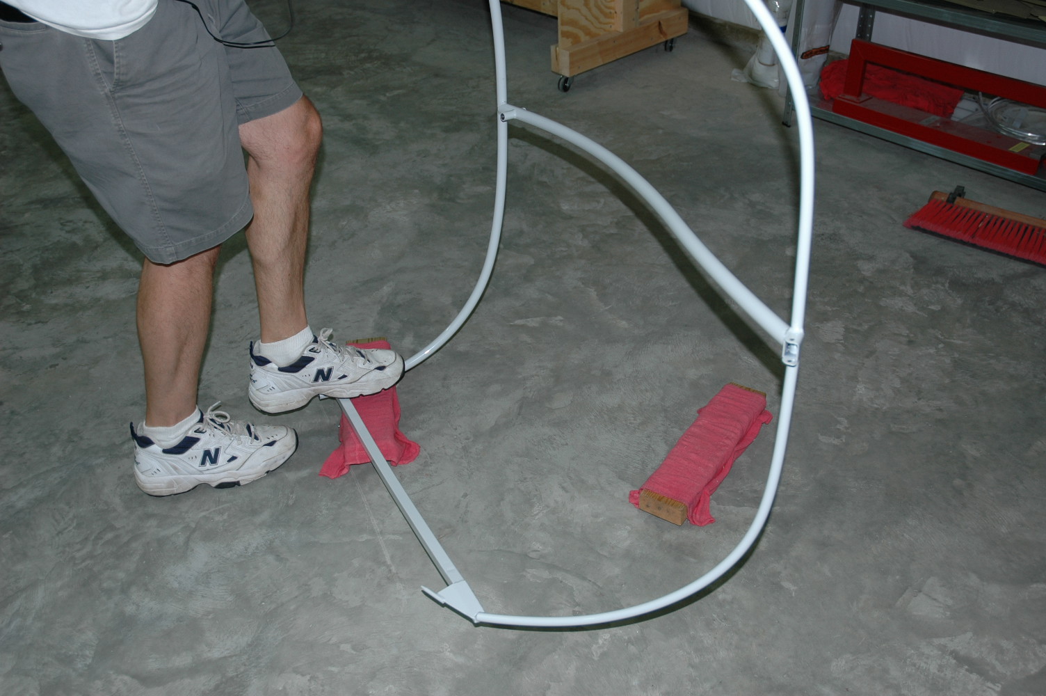
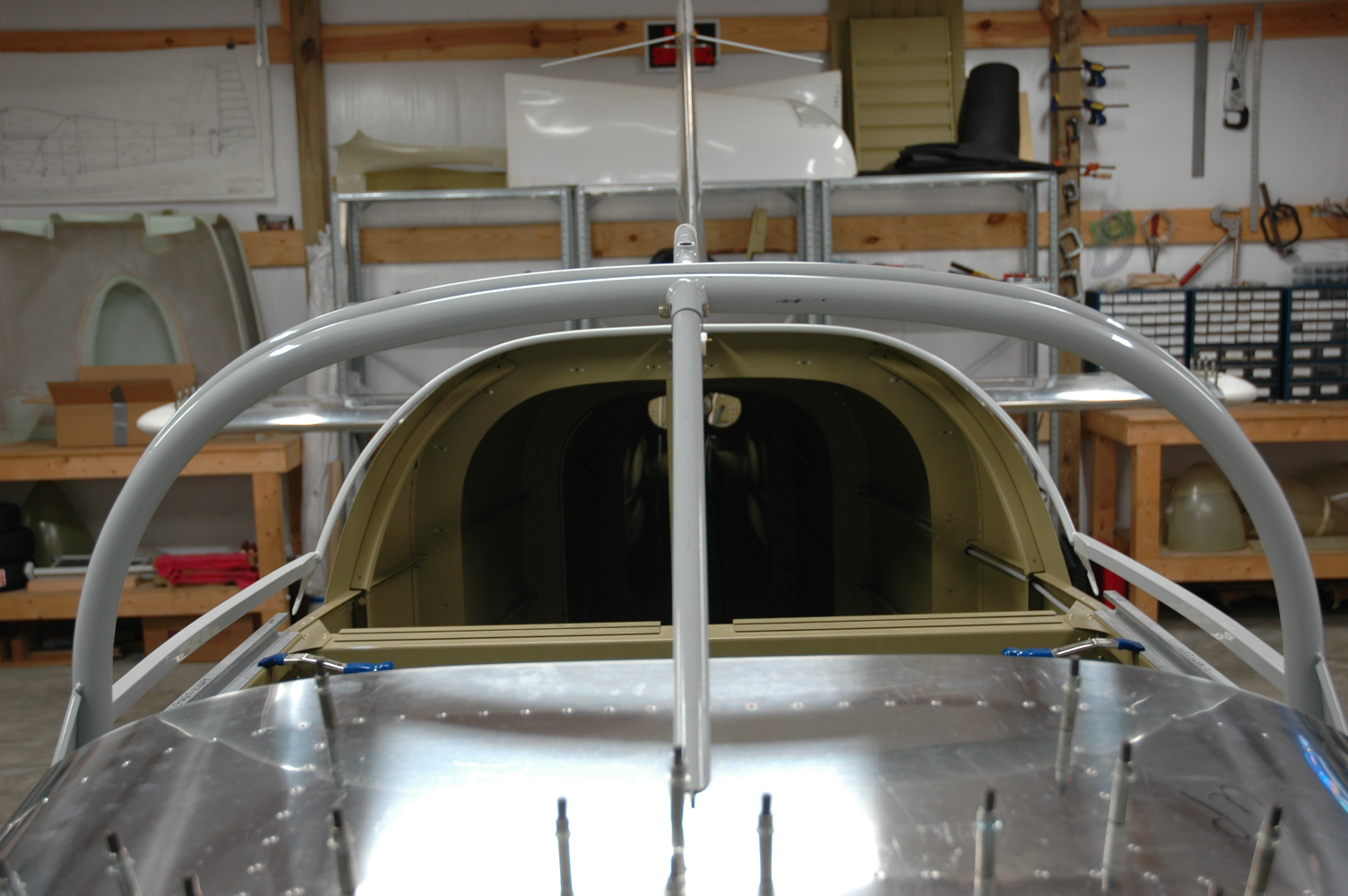
Got busy on my slider canopy frame. Been taking too much time off lately. Bent the forward left canopy bow forward some using 2x4s covered with rags to pad the frame; I isolated the forward bow at the center weld and the left side rail welds with the wood blocks. Worked really well and I got most of the gap out so that it more closely matches the right side bow when in place against the roll bar. Not perfect but I've got to move on. Also removed some bend in the forward bow to try and get the right sides skin-to-slider rail 1/16" distance...will continue this tomorrow.
|
|
|
2007-03-20 |
Hours: 1.75 |
Category:
Finish
|
|
Manual Ref:
10-2
|
ID#:
947
|
|
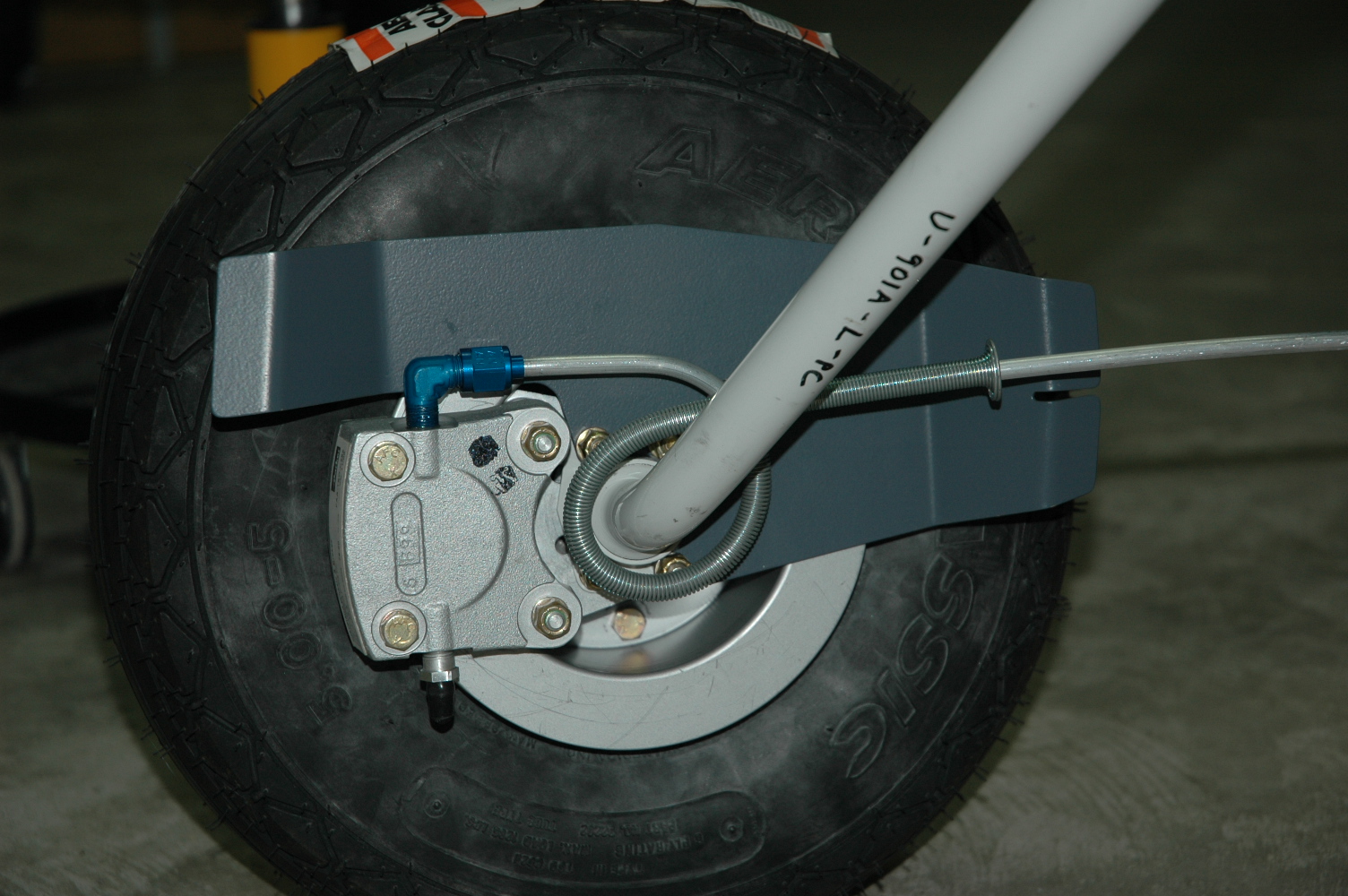
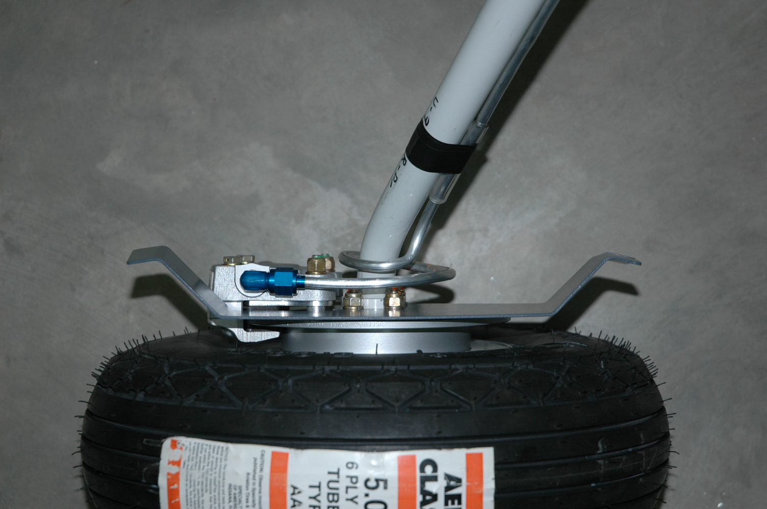
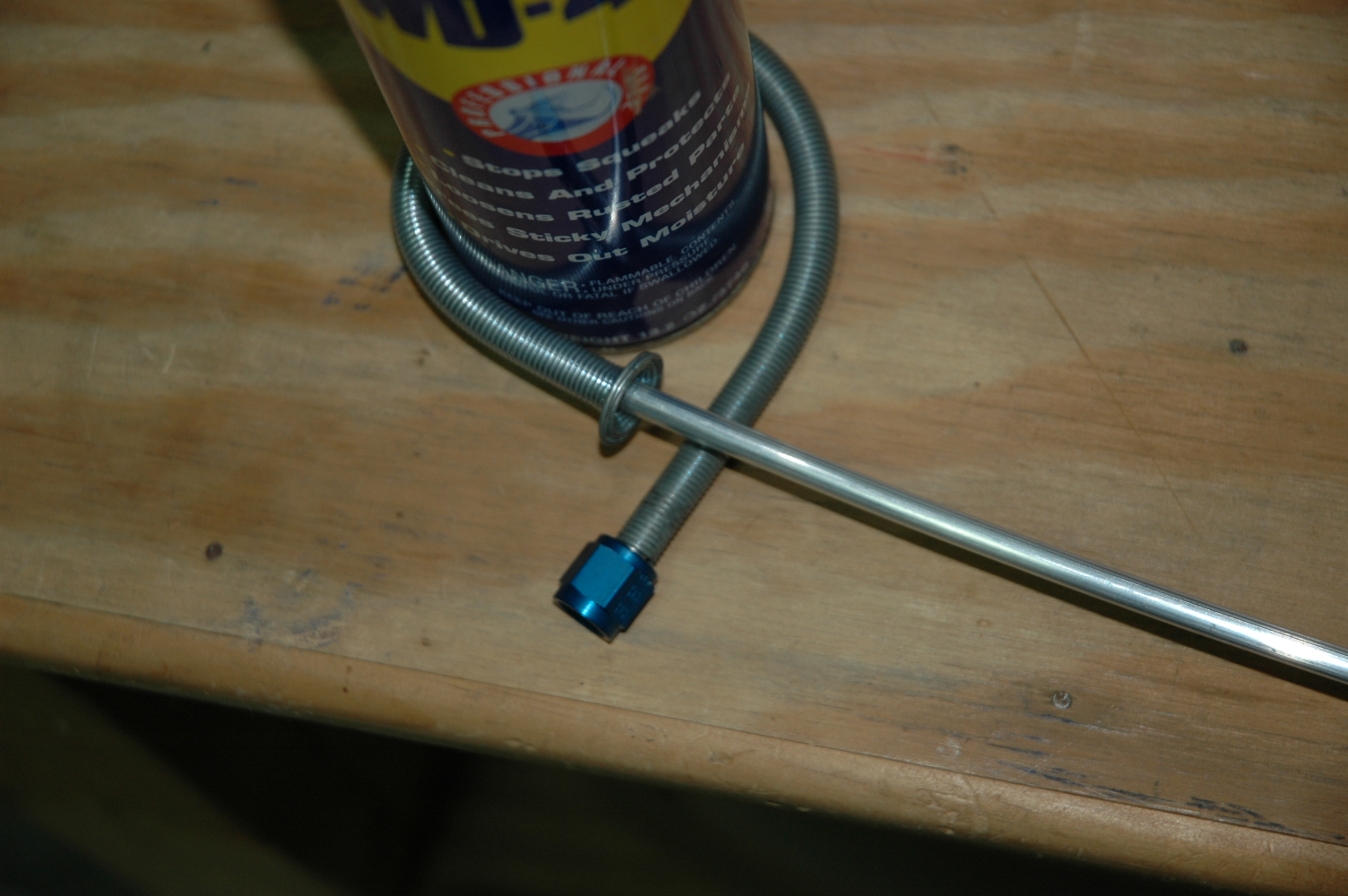
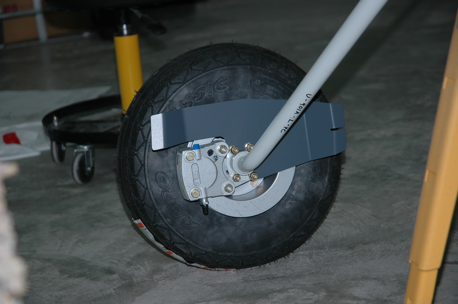
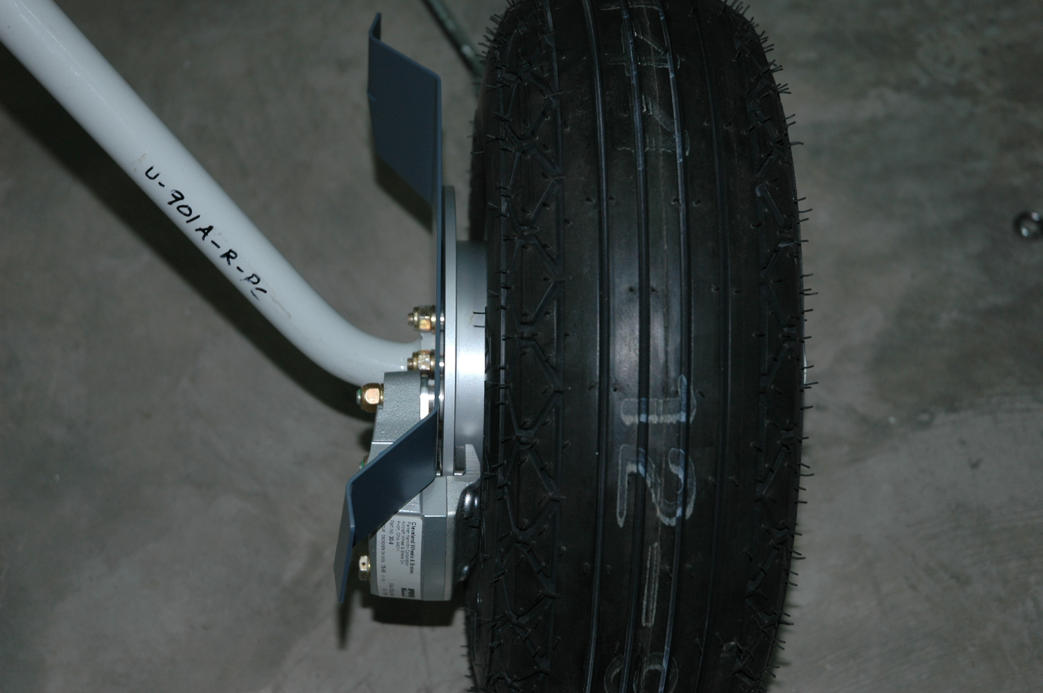
Checked gap between brake disc and 810 bracket; re-worked the brake lines |
|
Checked and corrected the gap between the brake discs and the 810 fairing brackets. Had to add a few washers to get the acceptable gap. Once satisfied, I torqued all four bolts on each side connecting the 810, spacers, Cleveland mount, and brake mount. Also, after reviewing other builders' websites, I decided to rework the brake lines from the fuse to the brake calipers because I think the brake lines need to "hug" the gear leg all the way to the bottom to where the leg bends. Originally, mine seperate from the leg a little too high and would have likely conflicted with the gear leg fairing at the lower end. I started again by wrapping the tube/spring bender around a can of WD-40 to get the initial curve started, then installed on the brake caliper and worked the tight bend to run the tube up to the fuse fitting. I'm getting pretty good at bending brake lines!
|
|
|
2007-03-19 |
Hours: 1.5 |
Category:
Finish
|
|
Manual Ref:
10-2
|
ID#:
946
|
|
Installed brake lines from fuse to brake calipers |
|
Installed the 1/4" aluminum brake lines from the fuse to the brake calipers. Started with about 3.5' length of tubing, flared at the caliper end with fitting nut installed. Put the spring tube bender on and bent around a can of WD-40 at about 1.5 from the end. Bent it around until it crossed back over at 90 degrees, then installed on the brake caliper and worked the bends around the gear leg and straight up to the fitting at the fuse. Cut three each side 2" lengths of 1/4" OD clear tubing and positioned them along the gear leg and taped into place with electrical tape. Made sure none of the tubing contacts the gear leg.
|
|
|
2007-03-18 |
Hours: 1 |
Category:
Finish
|
|
Manual Ref:
10-2
|
ID#:
945
|
|
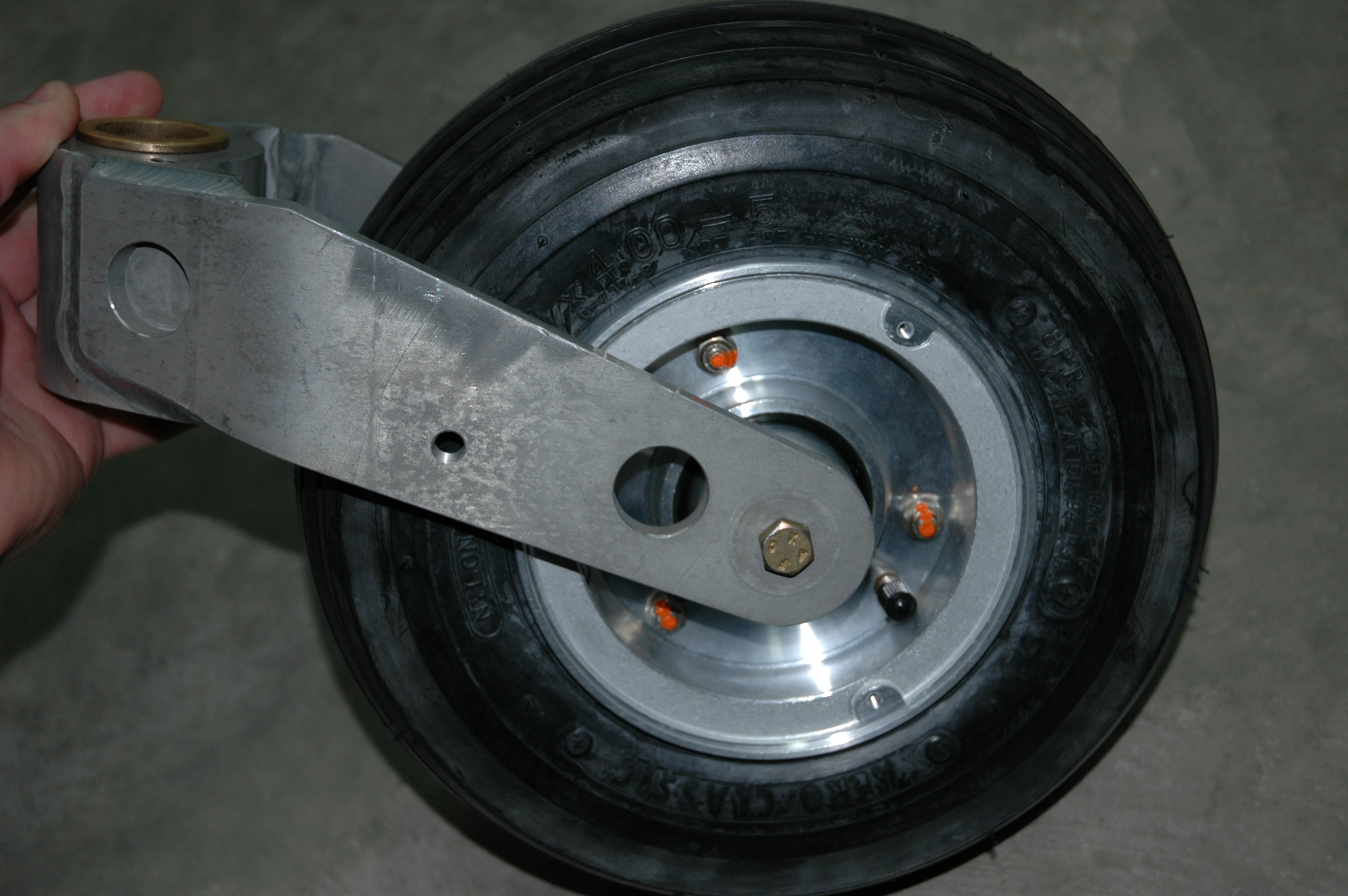
Installed the main wheels |
|
Installed the main wheels on the gear legs. The bolts for the installing the 403 brake mount to Cleveland mount to spacers and 810 fairing bracket are difficult to tighten because of the tight space to work in around the axle; have to do it slowly with two wrenchs or modify a socket wrench to fit. Did some more head scratching trying to figure out the brake calipers. Vans manual says to bolt them to the brake mount, but they actually "float" around the brake disc once installed. Remove the outboard brake pad bolts, install the caliper into the two slider holes on the Cleveland brake mount, insert the outboard brake pad between the tire and the brake disc, and re-install the bolts. The coil of brake line installed later will flex enough to allow for the floating brake caliper. Install the AN822 elbow fitting before installing the caliper because the 810 fairing bracket will be in the way.
|
|
|
2007-03-18 |
Hours: 4 |
Category:
Finish
|
|
Manual Ref:
10-1
|
ID#:
944
|
|
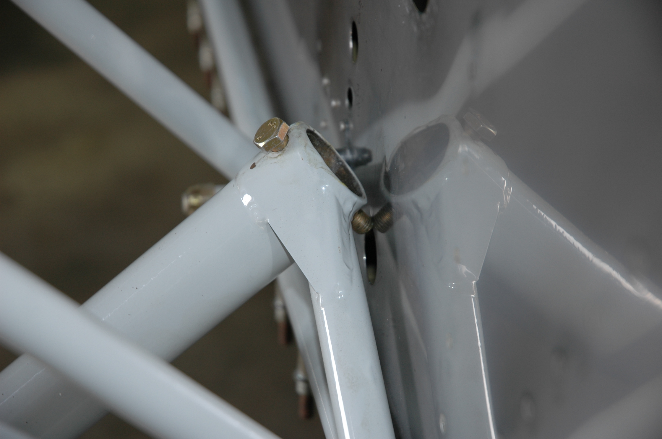
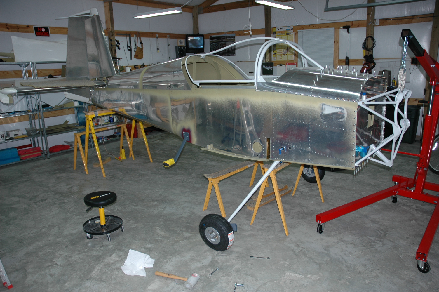
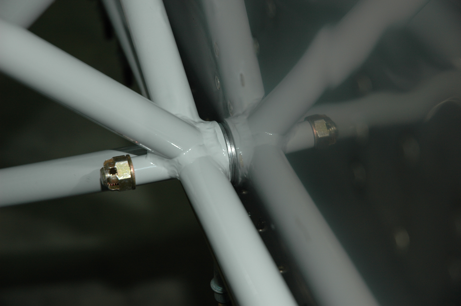
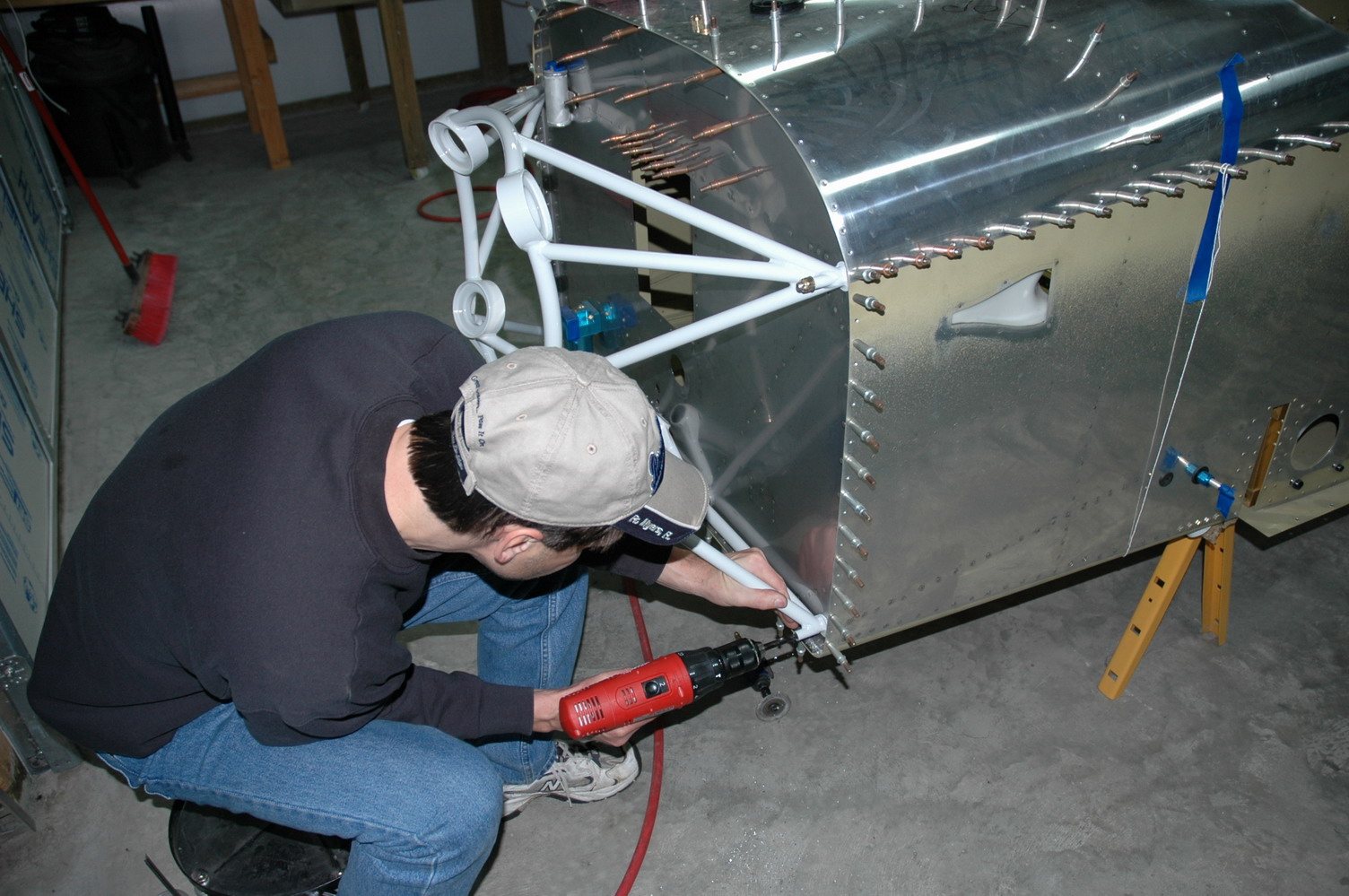
Installed the main gear legs |
|
Installed the main gear legs. Used an engine hoist strapped to the engine mount to lift the front. Bought the engine hoist last night and finished putting it together this morning. Didn't want to spend the $120 for it, but once I lifted the front end of the fuse up with it the first time, I was completely happy that I did. Also had to raise the height of the aft sawhorse to keep the plane level. As I worked to install the gear legs, I kept a sawhorse under the wing bulkhead to prevent a castrophic event if the engine hoist failed. I put a thin coat of bearing grease on the bear surfaces of the gear legs before inserting them to help stop corosion. The gear legs went in pretty easily and lining up the holes and installing the bolts went well.
|
|
|
2007-03-17 |
Hours: 2 |
Category:
Finish
|
|
Manual Ref:
10-1
|
ID#:
943
|
|
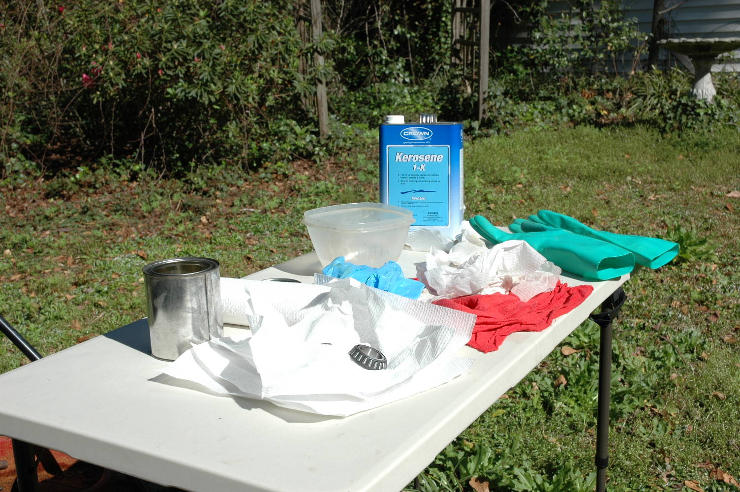
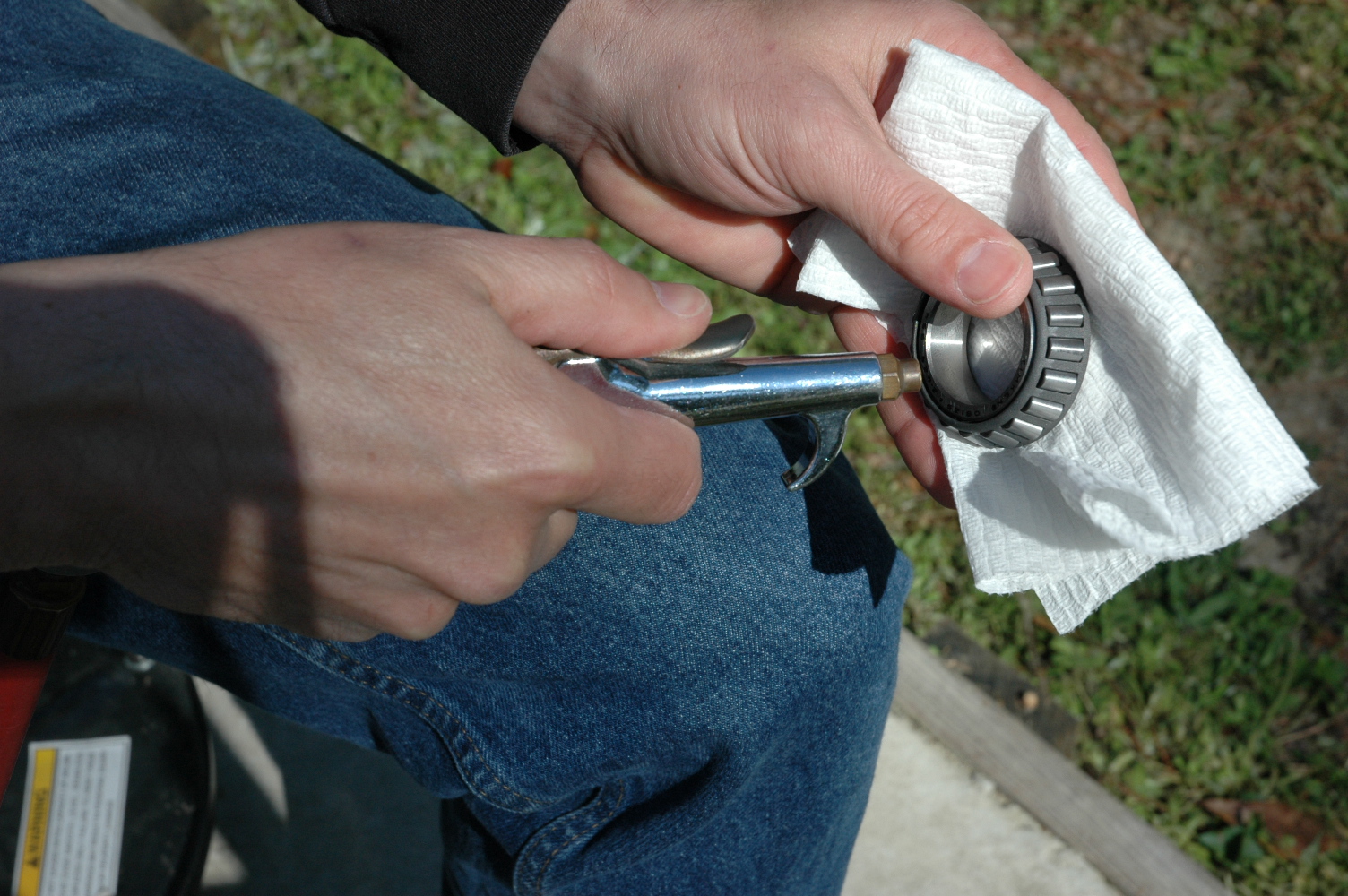
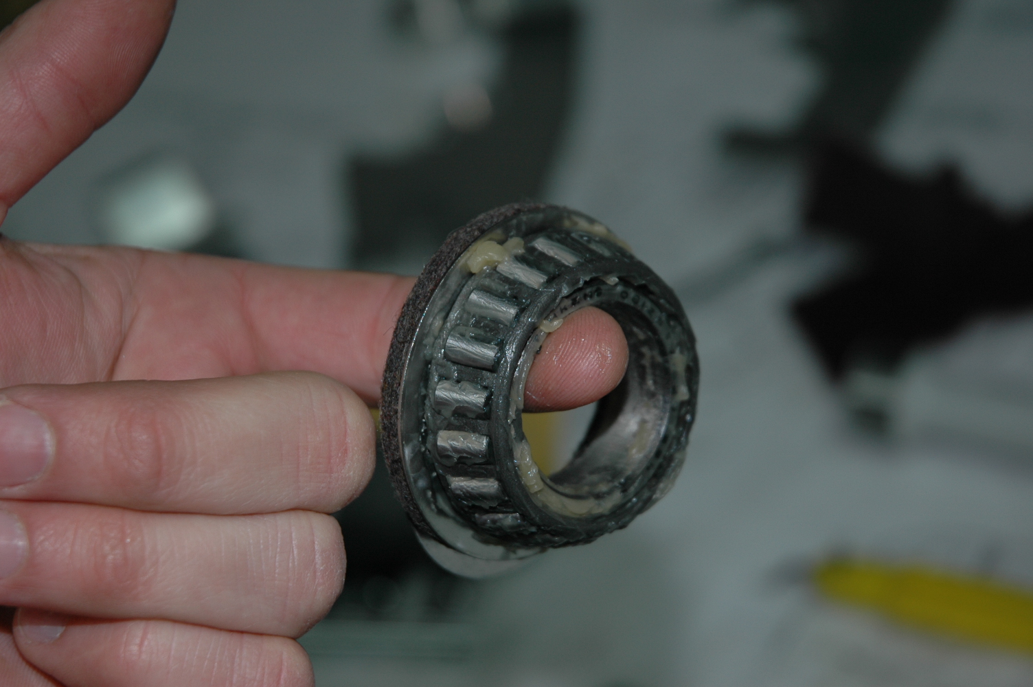
Cleaned and greased the main bearings |
|
Cleaned the main wheel bearings using K-1 Kerosene as the cleaning solvent. Rinsed them well by swishing them back and forth ridgedly in a bowl of kerosene to remove the existing grease as they were shipped with. Took a good bit of swishing to get all the clumps of grease out and get them completely clean. Once cleaned, I blew any solvent out of the bearings with compressed air for about five minutes each, making sure I didn't let the bearings spin and were completely dry. After that, fun with grease. I used Aeroshell #5 - a gallon can looks to be a lifetime supply! I used the glob in palm method with nitrile gloves on, compressing the grease thru the bearings by pushing the bearings into my palm of grease until grease extruded thru the top side of the bearings and then some more. Greased the wheel races, damped the felt seals with 10W-40 Castrol motor oil I had in the shop and installed the bearings into the wheels. They are ready to mount onto the gear legs when I get them installed.
|
|
|
2007-03-09 |
Hours: 1.5 |
Category:
Finish
|
|
Manual Ref:
10-6
|
ID#:
941
|
|
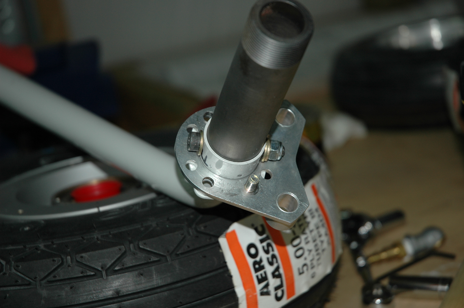
Mounted nose wheel to yoke |
|
Installed the nose tire onto the nose gear yoke. The tire is really hard to turn once bolted and torqued.
|
|
|
2007-03-07 |
Hours: 1 |
Category:
Finish
|
|
Manual Ref:
10-2
|
ID#:
940
|
|
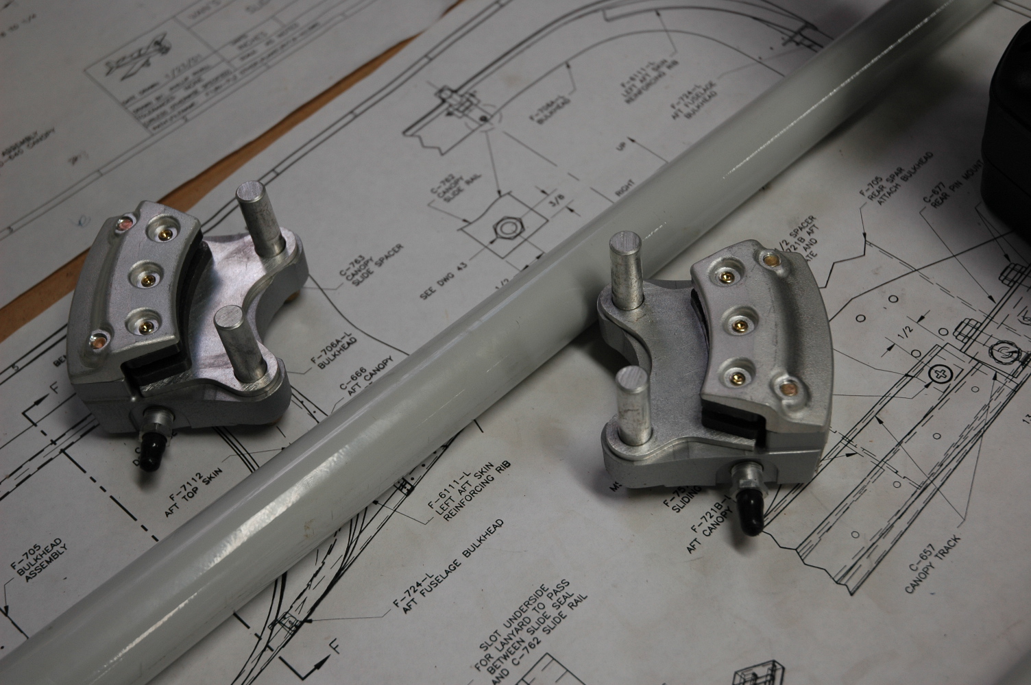
Painted the gear fairing attach brackets |
|
Painted the various gear fairing attach brackets with Nason acrylic sealer paint.
|
|
|
2007-03-06 |
Hours: 1 |
Category:
Finish
|
|
Manual Ref:
10-2
|
ID#:
939
|
|
Primed gear fairing attach brackets |
|
Primed all the gear fairing attach brackets. Weather was too nice, so I had to quit after that and go flying.
|
|
|
2007-03-05 |
Hours: 1.5 |
Category:
Finish
|
|
Manual Ref:
|
ID#:
937
|
|
Prepped parts for priming |
|
Studied the nose wheel DWG C-1 and got the various parts together. Prepped several parts for priming. They are the alclad parts that attached to each of the wheels to hold the wheel fairing on. Waiting on shipment of bearing grease to arrive so I can continue with landing gear assembly.
|
|
|
2007-03-03 |
Hours: 3.5 |
Category:
Finish
|
|
Manual Ref:
10-1,6
|
ID#:
936
|
|
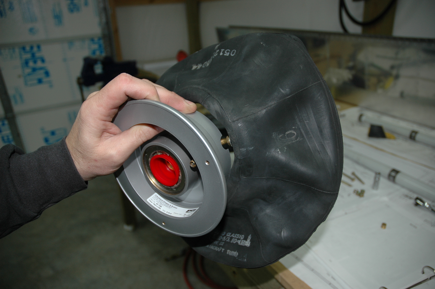
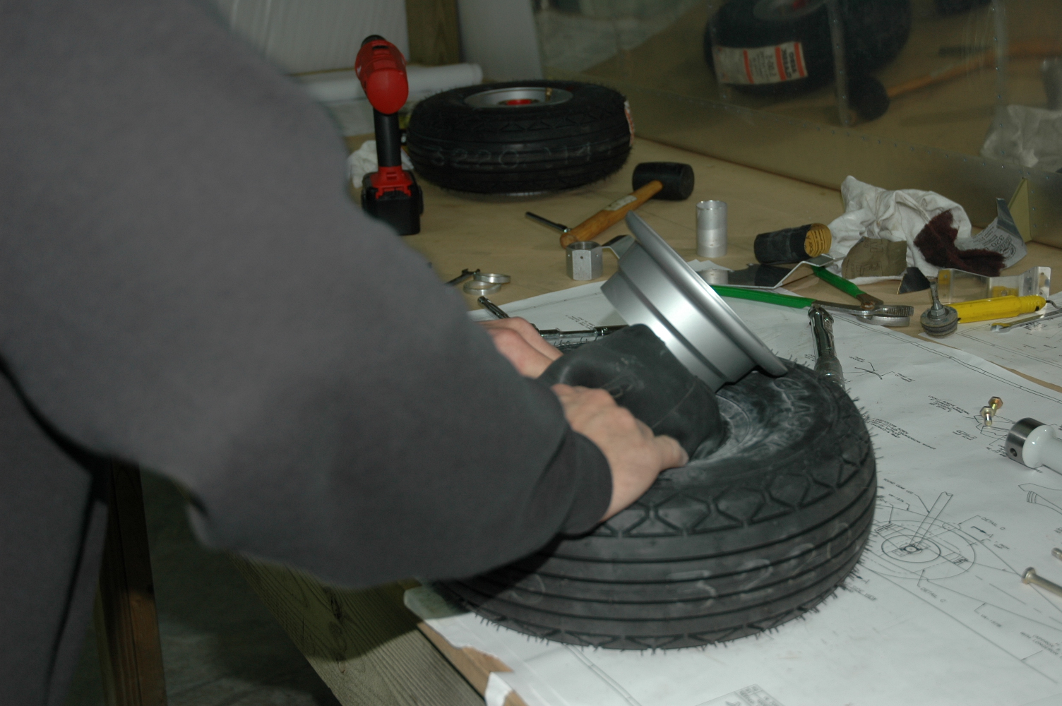
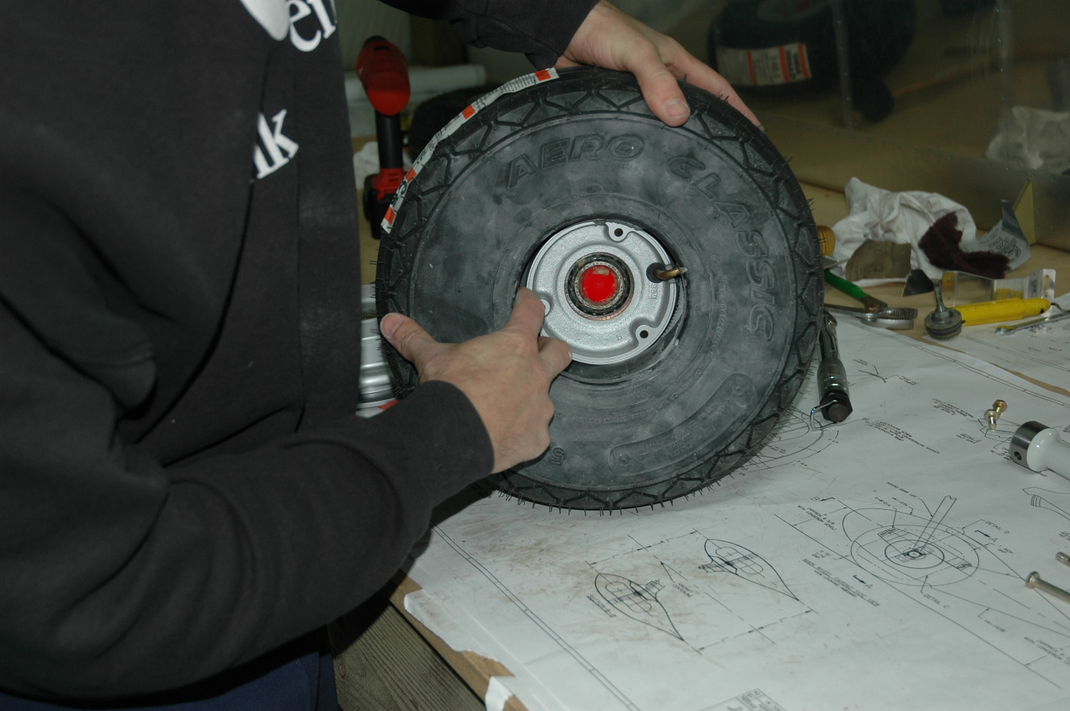
More tires, brakes, nose wheel |
|
Assembled the 2nd main wheel and nose wheel. The valve stem is difficult to insert in the wheel, so I did that first then installed the tube into the tire. The nose wheel was harder than the mains by far. You have to be careful not to pinch the tube. I put the outside half of the wheel in the tire snuggly as possible then inserted the tube, then the other half of the wheel. Slowly pressing the halves together, checking to make sure the tube is clear, I inserted one bolt and washer/nut to start it, then the other two, pressing the wheel halves together making sure they touch with a "metal" sound. Also cut the 408 spacers and deburred the fairing mount parts.
|
|
|
2007-03-02 |
Hours: 3 |
Category:
Finish
|
|
Manual Ref:
10-1
|
ID#:
935
|
|
Started assembling tires and worked on installing brakes on gear legs |
|
Started working on the gear legs. Installed the 403 brake flanges and Cleveland mounting flanges on the gear axles. The Cleveland mount hole needed some sanding/scotchbriting to enlarge slightly to fit onto the 403 flange. Installed the screws thru the 403 flange/axle. Test fitted the U-810. Assembled a wheel/tire and test fitted it to the left gear leg. Of course, I had to roll it around on the floor making tire screeching noises! The tire/wheel was a challenge. The manual says to fully grease the bearings. They look greased, but since I have never done this, I don't know what fully grease looks like. I'll inquire about greasing the bearings properly.
|
|
|
2007-03-02 |
Hours: 1 |
Category:
Finish
|
|
Manual Ref:
10-1
|
ID#:
934
|
|
Installed engine mount spacers |
|
Made and installed two spacers required for the middle lower two engine mount bolts. I cut them from .063 alclad with a 1.125" hole saw. They could be 1.25" to match the mount size but I don't have a 1.25 hole saw. I think 1.125" will do just fine. I will check with Vans on this.
|
|
|
2007-03-01 |
Hours: 2.75 |
Category:
Finish
|
|
Manual Ref:
10-1
|
ID#:
933
|
|
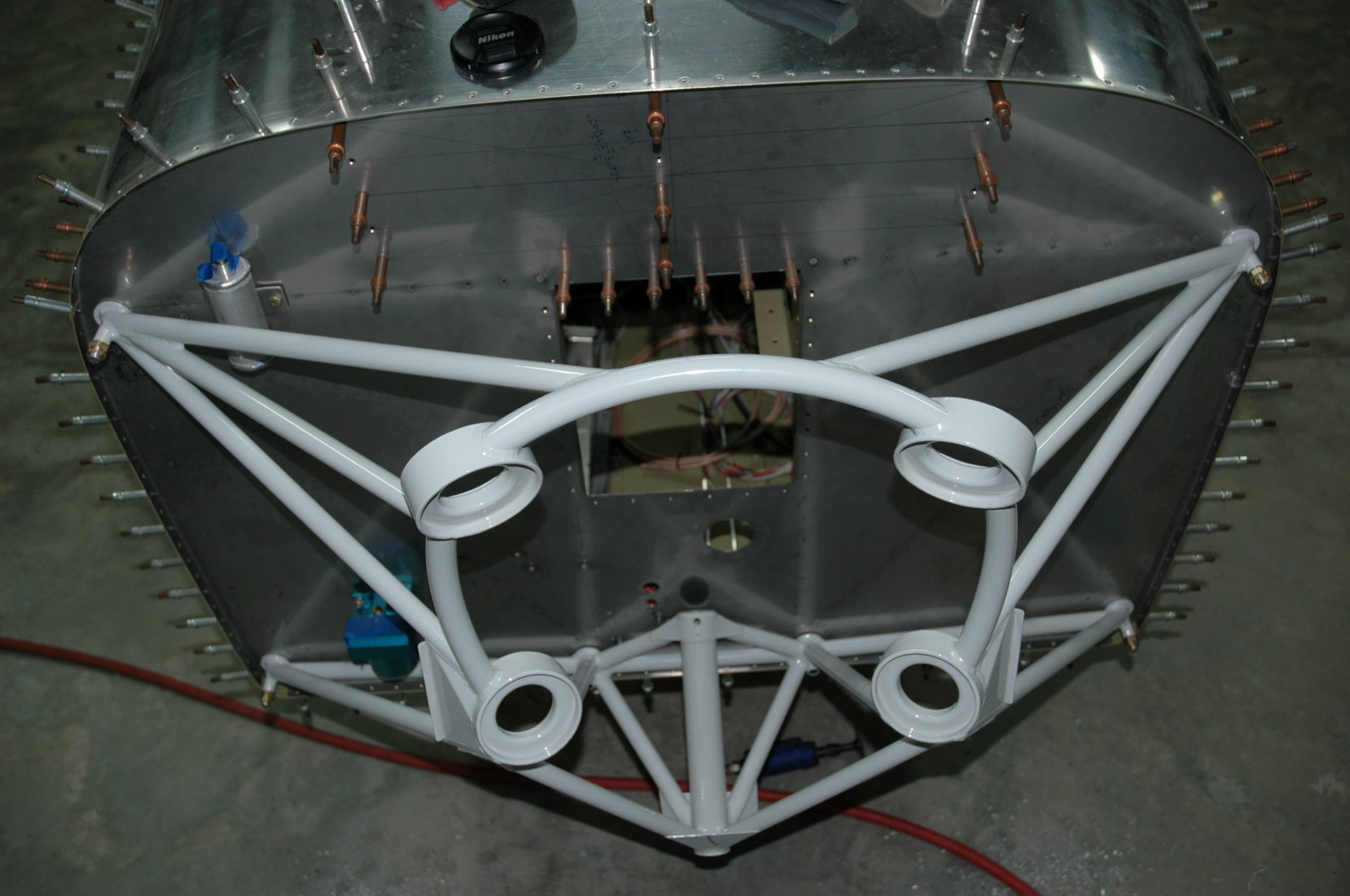
Intalled the engine mount |
|
Drilled the upper left (facing aftward) hole thru the firewall, stepping up to final size of 3/8" for the engine mount. Installed the bolt and hung the engine mount. The other holes do not line up, so I quit and went looking on the internet for answers. After reading several websites and searching Vansairforce.net I drilled the upper right hole to size and remounted the engine mount with both top bolts. The engine mount had to be worked a little to get the right side bolt installed. Then drilled the bottom left, installed the bolt, then the bottom right. In the bottom holes, since the mount remained on the firewall, I started with a 23/64 drill, then finished with the 3/8". I didn't want to ream out the engine mount hole as I drilled thru it into the firewall. After the four corners were drilled, I drilled the two center bottom holes and installed the bolts. There needs to be 1/16" spacers/washers at those two center bottom holes between the firewall and the engine mount as there is a gap there.
|
|
|
2007-03-01 |
Hours: 0.5 |
Category:
Finish
|
|
Manual Ref:
10-1
|
ID#:
932
|
|
Moving on to the engine mount |
|
Decided to do some work on the project today. Slider has me agrevated, so I worked on installing the engine mount. Held it in place on the firewall to get a feel for how it will go on and noticed that the lower fuel pump bolt and platenut interfer, so it will have to be trimmed to allow the engine mount to fit nicely. DWG 36A, ISO FRONT VIEW points to the upper bolt/platenut, but that one does not seems to be a factor; the bottom one definitely is, so I trimmed off the visible bolt thread and about 1/32" of the platenut - hoping this would be enough. It was. On to drilling engine mount bolt holes in the firewall.
|
|
|
2006-11-13 |
Hours: 1 |
Category:
Finish
|
|
Manual Ref:
9-10
|
ID#:
927
|
|
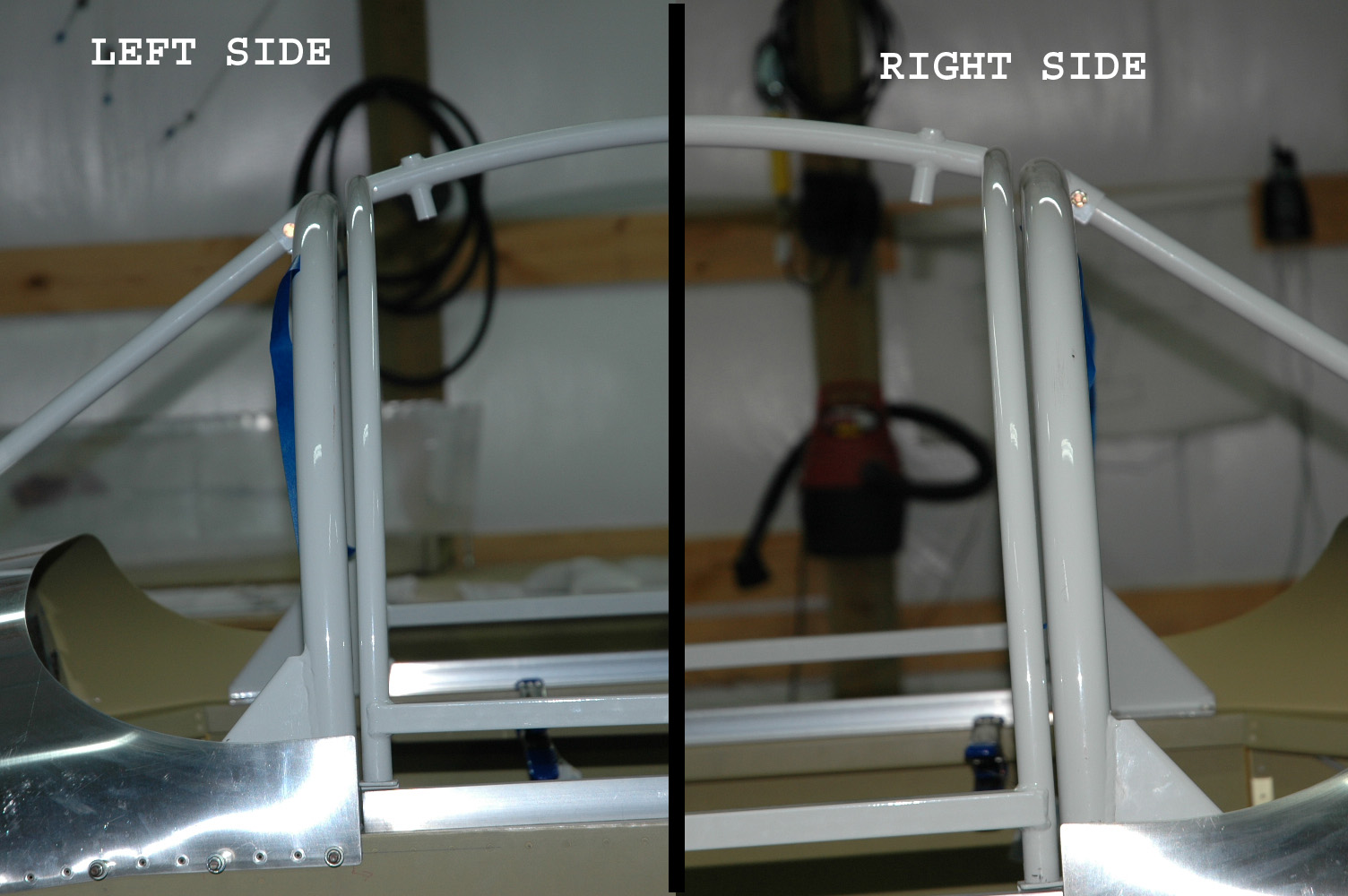
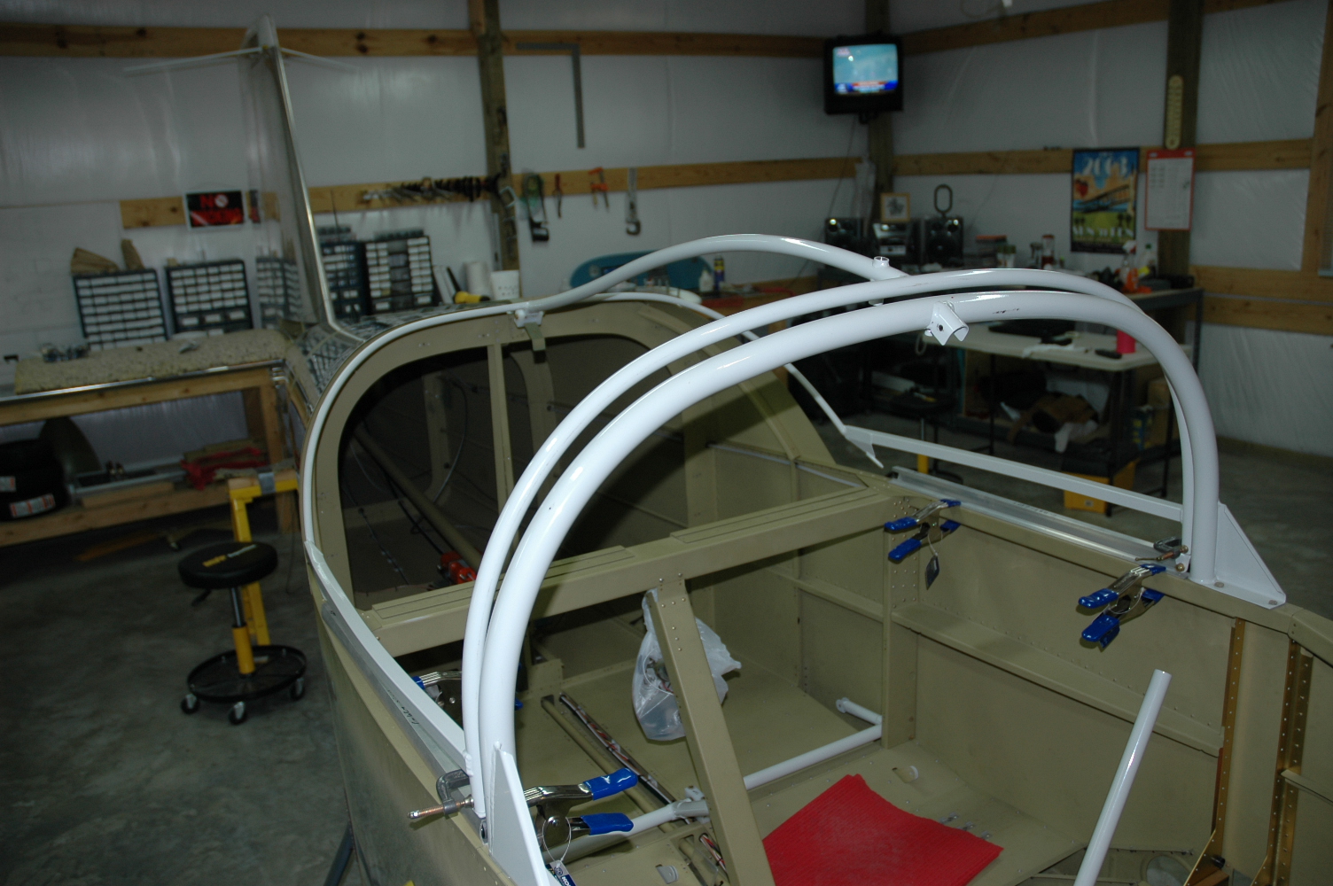
More tinkering with the slider frame |
|
The view from each side shows that the front bows have a larger gap towards the top. Not sure how to correct this. More head scratching today. A view from the front after having trimmed the bottom tubes of the front bow to get the 3/8" difference in the heights of the slider front bow and the roll bar still shows the left side slightly higher at the 1 oclock position.
|
|
|
2006-11-12 |
Hours: 2 |
Category:
Finish
|
|
Manual Ref:
9-10
|
ID#:
926
|
|
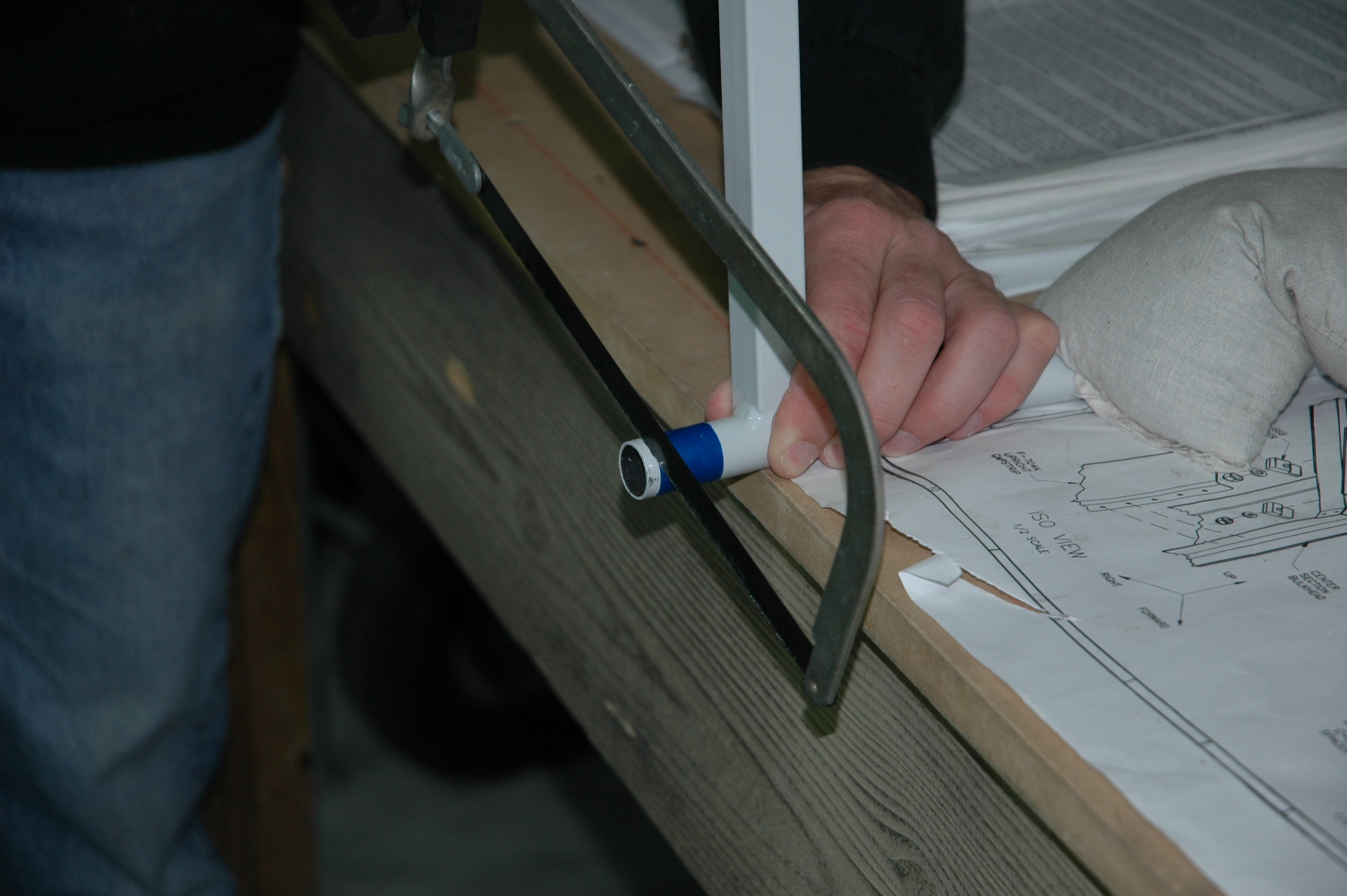
Did a bunch of head scratching, trying to move forward on the slider. The left side front bow is slightly higher that the right side, so I measured the distance from the top of the roller track to the bottom of the slider side rail. Left side was about 3/16" longer, so I cut that much off the bottom of the tube. Replaced the slider frame and and measure the distance of the top center bow above the roll b ar. Needed to trim the front bow lower tubes on both sides another 5/16" each to bring the center top front bow down to 3/8" above the roll bar top center per the plans. Viewing from the from the left side 1 oclock position of the bow is clearly higher than the same position on the right side of the front bow. More head scratching to figure out what to do next.
|
|
|
2006-08-27 |
Hours: 1 |
Category:
Finish
|
|
Manual Ref:
9-9
|
ID#:
924
|
|
Started back on canopy work |
|
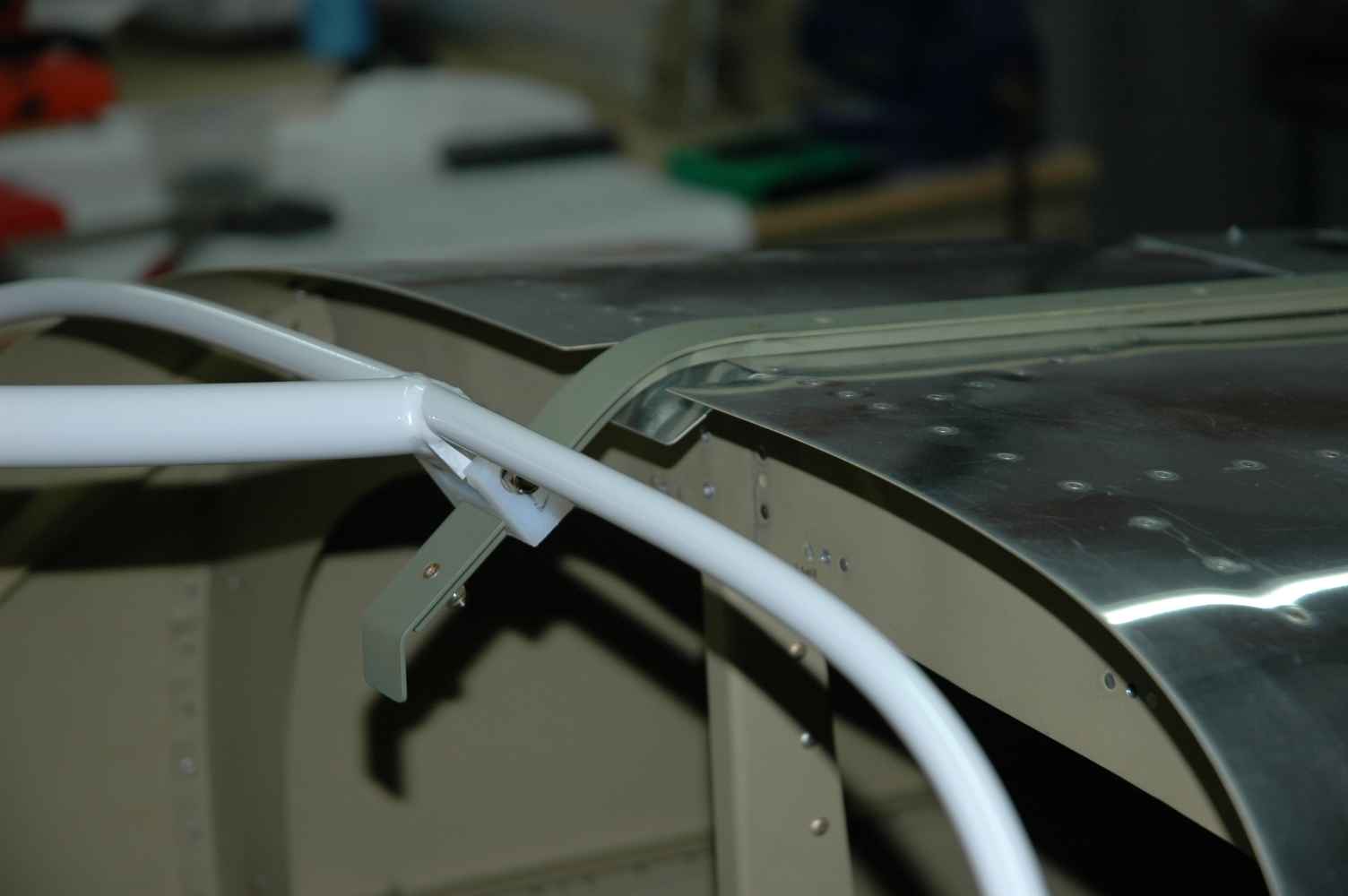
Clamped the 657 canopy tracks to the canopy decks. Added the canopy frame, bent the aft fuse skin tab and taped the slider track to the aft fuse. Lots of work to do here!
|
|
|
2006-01-08 |
Hours: 2.5 |
Category:
Finish
|
|
Manual Ref:
|
ID#:
841
|
|
Finished inventorying the finish kit |
|
Got all the little bags of goodies inventoried and stored in the bins. Ready to get building again.
|
|
|
2006-01-07 |
Hours: 3 |
Category:
Finish
|
|
Manual Ref:
|
ID#:
840
|
|
Inventoried the finish kit |
|
Inventoried all the finish kit parts and most everything that came in the little bags. Unloaded the bags of rivets into the rivet bins. Most all of rivet bags were in clear plastic and sealed. They have the bag numbers and contents - ie, "AN426-3-4 rivets" printed on the bags. This is a nice new development from Vans. Still have several hardware bags to inventory. Spent some time getting my fastener/hardware bins in order. I have done this slowly over the past couple of years, but I'd recommend doing it from the very start. Instead of keeping all hardware stored in bins according to Vans bag numbers, go ahead and seperate the rivets, AN bolts, nuts, washers, etc. according to their AN numbers. That way, when the plans call for an AN3-5A bolt or whatever, you go to the AN3-5A bolt bin and get one and while you are at it, get the nylock nut and washers from their appropriate bin trays too! Takes way more bins, but will save time in the long run to keep from having to open every bin tray to find something. Also will help familiarize new builders like myself with the nomenclature of the vast number of fasteners and hardware you will encounter.
|
|
|
2006-01-06 |
Hours: 0 |
Category:
Finish
|
|
Manual Ref:
|
ID#:
839
|
|
ABS delivered my finish kit today. Came in one huge 4'x8'x2' crate. Turns out the driver, Bobby, knows my brother and sister-in-law. Small world. We off-loaded the crate into the back of my pickup. I can handle it from there. I immediately tore into the crate with a huge screw driver and hammer to remove the top. Just like Christmas! Another well-packed crate. Didn't see anything damaged on my initial overview. Nice fiberglass work on the wheelpants, spinner, and cowling! The two main tires and their tubes are back ordered, but I won't need them for quite awhile anyway. And the saga continues!
|
|
|
2006-01-03 |
Hours: 0 |
Category:
Finish
|
|
Manual Ref:
|
ID#:
838
|
|
Letter from Vans arrived today with kit shipping info |
|
Shipping information arrived today from Vans. I called the freight company and they expect to deliver my Finish Kit Jan. 9th.
|
|
|
2005-10-23 |
Hours: 0 |
Category:
Finish
|
|
Manual Ref:
8-10
|
ID#:
782
|
|
Received pink paper finish kit delivery notice |
|
Received my pink paper today from Vans today! The expected ship date is 12-26-05 so I hope to have the finish kit by New Years.
|
|
|
2005-10-11 |
Hours: 0 |
Category:
Finish
|
|
Manual Ref:
|
ID#:
767
|
|
Mailed payment for my finish kit today |
|
Let go of a chunk of dough today. Mailed Vans the payment for the finish kit. Ouch! Hope to have it by Christmas!
|
|
|
|
|