|
|
|
|
|
|
Official building time: 2224.3 hours.
|
|
|
Building time for Wing: 607.5 hours.
Number of records for Wing: 274. |
|
2007-03-05 |
Hours: 0 |
Category:
Wing
|
|
Manual Ref:
|
ID#:
938
|
|
Dynon heated pitot tube arrived today! |
|
Finally, Dynon sent my heated pitot assembly. Put my name on the waiting list a couple or few years back. They finally got it perfected and sent me a notification that it was ready to order if I still wanted it. I sent in the order immediately about mid-Feb. it came in today. Test-fitted the pitot mount and it fits nicely. It came with a controller unit that I hope I can mount easily in the wing nearby the pitot tube.
|
|
|
2006-04-22 |
Hours: 4 |
Category:
Wing
|
|
Manual Ref:
|
ID#:
902
|
|
I am ready to remove the wings from the fuse so I built a new wing cradle so I can move it around on wheels. The original wing cradle was cut in half so i could store the wings in my old shed easier and allow more work space in there. The new cradle as 2" wheels so I can move it when necessary.
|
|
|
2006-01-23 |
Hours: 1.75 |
Category:
Wing
|
|
Manual Ref:
|
ID#:
849
|
|
Finished initial fitting of wing tip LED nav light boards |
|
Finished fitting the wing tip LED nav light boards today. Got the left wing tip hole cut out and installed all the platenuts. The hole was big enough to reach and squeeze the rivets with the flange yoke, so that was nice. The holes had to be cut large and odd shaped to get the board to fit nicely. Installed the lens and fired both wing tips up to see how they look. I will put permanent lead wires on later and clean the circuit boards and apply the conformal coating. I have some West System epoxy so that is what I will use.
|
|
|
2006-01-17 |
Hours: 4 |
Category:
Wing
|
|
Manual Ref:
|
ID#:
850
|
|
More work on assembling wing tip LED nav lights |
|
Spent a bunch of time assembling the LED boards. Got both of them put together. Emailed CreativAir with a few questions yesterday. To my surprise, Bill VonDane of CreativAir called this morning to answer a few questions and give me some pointers. Told me how to build a jig to put the boards on while soldering the LEDs. I made it and it worked great. It is for the 15 "straight" LEDs. You cut two 6" lenghts of 2x6 lumber, drill the three screw holes in one and put some long 8-32 bolts in from the back. Then place this assembly on top of the other piece of 2x6 and screw them together with deck screws. You now have a sturdy block with three 8-32 bolt shafts sticking up about an inch. Place a long bushing and two short ones that came with the LED kit onto each bolt and then put the board in place with LEDs inserted. They are facing down and just contact the board. Place some springs on the bolts and then put the nuts on. This will keep the board from moving or vibrating. When I finished I had two LEDs on each board facing the wrong (opposite) direction, so I corrected those. There is a picture below showing this. One thing Bill told me is that the boards are designed for the old style wing tips so you need to make some adjustment for the newer tips like I have (circa 2003). Works out okay, but the kit needs to be updated. I simply cut the LED boards to fit the wing tip instead of relying on the cut line printed on the board. Next I cut the hole in the right wing tip and test fitted the nav light assembly. The hole needs to be cut a bit bigger than directed. Note about soldering: my cheap pencil style soldering iron worked just fine, except one thing I noticed is I believe it cycles, so at times it is not as hot as needed to get those one second solders. It wasn't soldering that quickly, so I had to just wait for it to cycle in and then the soldering was a matter of touching the iron on one side of the lead wire down at the board and the solder on the other side and the lead solders very quickly - should be able to get them in a second or less.
|
|
|
2006-01-16 |
Hours: 3 |
Category:
Wing
|
|
Manual Ref:
|
ID#:
847
|
|
Started assembling wingtip light kit |
|
Started working on my CreativAir wingtip light kit. I choose the LED/strobe combo set. Started by separating the regulator board and LED boards. I put some blue painters masking tape over the board on either side of the white cut line to protect the boards. The I cut the line with a dremel drill cutoff wheel. This went really easily. I recommend using a mask. Then I marked cut lines on each (red and green) regulator board 1/8" away from the outermost circuit trail, then put protective tape on the circuit boards and cut the excess board off each end. Then I smoothed the edges gently on the belt sander. Went to work soldering resistors and regulators to each board. This is quite entertaining. I started with the resistors per plans as they can withstand more abuse as you progress thru the learning curve on soldering. One thing you need to do is make sure the soldering iron is hot enough. I tried to start soldering with poor results and after some time I was getting the solder connections done in about 1 to 2 seconds. Need to give the soldering iron about 25 minutes to heat up nice and hot enough to get those quick solders.
|
|
|
2005-12-15 |
Hours: 1.5 |
Category:
Wing
|
|
Manual Ref:
8-15
|
ID#:
826
|
|
Installed wing tip lens nutplates |
|
My #33 drill came in from ACS so I went ahead and drilled out the nutplates for the pop rivets and installed them on the wing tips. I screwed the lenses on to see how they fit. Not exactly happy with the results. I may work some Super Fill or epoxy in the gaps to make them look/fit better.
|
|
|
2005-12-11 |
Hours: 2 |
Category:
Wing
|
|
Manual Ref:
|
ID#:
824
|
|
More work on the wing tip lens |
|
Shaped the other wing tip lens and got it to fit nicely. Drilled the holes for the nutplates/screws. I haven't figured out yet how to install the nutplates. Don't want to attempt to buck them with the flush set. Might crack the fiberglass. Can't squeeze them. Hum. Might have to use pop rivets. More later.
|
|
|
2005-12-10 |
Hours: 3.5 |
Category:
Wing
|
|
Manual Ref:
|
ID#:
823
|
|
While I am waiting for help to move the fuse to the center of the workshop and fit the wings, I worked on cutting and fitting the wing tip lens. I couldn't find the direction sheet at first but after turning the workshop and dog house upside down, I finally found the sheet and hardward in the parts bin where I put it over a year and a half ago so I wouldn't lose it! Anyway, the direction sheet is actually pretty useless. I found other builder's websites much more helpful. Just cut the lens in half, shape to fit along the fore/aft axis, then cut to fit in the other direction. Go slow, removing plexiglass little by little until the fit is right. I used the belt sander with much success. Then I smoothed the edges carefully with a fine file. Oh, yeah, don't mark on these lens with permanent markers for obvious reasons! My friend Robert came by later in the day and we moved the fuse to the center of the workshop. I should be able to get both wings fitted with about 1.5 feet to spare on each end.
|
|
|
2005-02-21 |
Hours: 2.75 |
Category:
Wing
|
|
Manual Ref:
7-16
|
ID#:
577
|
|
Riveted the W-916 ribs into the wing tips |
|
Finally got around to riveting the W-916 ribs into the wing tips.
|
|
|
2005-01-06 |
Hours: 0.75 |
Category:
Wing
|
|
Manual Ref:
7-16
|
ID#:
548
|
|
More work on the wing tips |
|
During work breaks today, I spent some time on the wing tips, trying to get those finished. I enlarged the tool holes of the W-916 tip ribs to 2.25" dia. per plans. Countersunk the right wing tip holes for the W-916 tip rib.
|
|
|
2004-12-19 |
Hours: 4.5 |
Category:
Wing
|
|
Manual Ref:
7-16
|
ID#:
537
|
|
More work on the wing tips |
|
Had an unnecessarily long day in the dog house today. I started the day drilling and clecoing the right wing tip to the wing. This took a little finesse as did the left wing tip to get it to fit nicely and get the TE to align with the aileron TE. The finished tip resulted in it being slightly off of align with the aileron TE by probably 3/16" after the W-916-L tip rib was drilled and clecoed into place. I had to re-working the wing tip a bit to get the fit as good as I could. Note: the W-916-R tip rib goes on the left wing, and the W-916-L tip rib goes on the right rib. I wish I had checked the drawings more closely. I had them reversed and had to switch and redrill and clecoe them into place. I used the same holes previously drilled in the wing tips and luckily, the properly fitted W-916 ribs aligned so that new holes could be drilled in them far enough away from the first set of rivet holes to work nicely. On the left wing tip I did earlier, I was wondering why the wing tip aft portion that lines up with the aileron looked so odd. But once they were switched, the wing tips look much nicer! Duh! I think Van's nomenclature for parts numbering is that, with regards to wing parts, if the part (ie, ribs of all sorts) aligns parallel to the direction of flight, the direction, left or right, that the flange points is the L or R label for the part. So, the W-916-R points to the right but goes on the left wing tip. Wonder why I hadn't figured this out before.
|
|
|
2004-12-18 |
Hours: 2.5 |
Category:
Wing
|
|
Manual Ref:
7-16
|
ID#:
536
|
|
Trimmed the right wing tip |
|
Trimmed the edges and made the cuts per plans on the right wing tip. Looks like it fits nicely, so I'll hopefully be drilling and clecoing the tip to the right wing tomorrow.
|
|
|
2004-12-16 |
Hours: 2 |
Category:
Wing
|
|
Manual Ref:
7-16
|
ID#:
535
|
|
Drilled and clecoed the W-916 tip rib |
|
Removed the left wing tip and marked the rivet lines top and bottom, and re-clecoed the tip back onto the wing. Positioned the W-916 tip rib into place, holding it with several clecoe clamps, then drilled and clecoed to the wing tip. Resulted in a very sturdy structure along the aft edge at the aileron. Re-checked the alignment and it looks to be good.
|
|
|
2004-12-16 |
Hours: 1.5 |
Category:
Wing
|
|
Manual Ref:
7-16
|
ID#:
534
|
|
Re-worked the top row of left wing tip to skin rivet holes |
|
Re-drilled the top row of wing tip to skin holes to #30's, making sure the wing tip TE was aligned with the aileron. This resulted in the TE's being nicely aligned. Had to remove and finish-trim the aft edge of the wing tip along the aileron to get the 1/4" gap per plans. The leading edge has a significant gap where the tip just will not fit snuggly into the wing skin LE. I tried to squeeze the tip at the leading edge to work it in, but it would take too much pressure, which might cause it to crack. I did create a fine hairline crack already, so I backed off and settled for what I ended up with. This will have to be built up with some epoxy and filler I suppose. I guess I'll be learning about fiberglass work very soon!
|
|
|
2004-12-15 |
Hours: 2 |
Category:
Wing
|
|
Manual Ref:
7-16
|
ID#:
533
|
|
Drilled and clecoed the left wing tip to the wing |
|
Fitted the left wing tip into place on the wing and drilled and clecoed. Great attention needs to be paid on making sure the aileron and wing tip trailing edges are align in the proper aileron neutral position. You cannot simply clamp them toegether and go to work drilling and clecoing. I ended up with the tip trailing edge about 1/2" lower (not more aft) than the aileron. So I removed the bottom clecoes, realigned the tip with the aileron and redrilled them with #30 and clecoed along the way. Removed the clamp from the aileron/wing tip trailing edge and yet again the tip is 3/8" lower than the aileron. I will repeat this procedure with the top holes tomorrow, making sure the aileron and wing tip trailing edges are aligned and do not move. The problem is that the aileron, although in neutral position, has about 1/4" play in it, so it needs to be securely held while working with the wing tip. This is probably why Van's suggests in the manual that a helper is useful here.
|
|
|
2004-12-15 |
Hours: 1.5 |
Category:
Wing
|
|
Manual Ref:
7-16
|
ID#:
532
|
|
Prepped the left wing tip for installation |
|
Marked the cut lines for the aft part of the wing tip flanges to the trailing edge with the reinforment strip clamped into place as a guide. Trimmed the top and bottom areas per plans so the tip flanges will clear the aileron attach bracket and the aileron itself. More will be trimmed once the tip is installed properly to get 1/4" clearance between the tip and the aileron. Had to trim some of the tip flange where the wing's J-strip extends beyond the outboard rib just slightly. Test fitted several times to get the tip to fit properly, trimming the tip flange where necessary to get it to fit nicely.
|
|
|
2004-12-14 |
Hours: 1.5 |
Category:
Wing
|
|
Manual Ref:
7-15
|
ID#:
530
|
|
Started working on left wing tip |
|
I used one of the wing tip reinforcement strips as a guide for how much to trim off the edges of the wing tip by cleco clamping it into place, butt up against the raised seam where the wing skin will fit. I marked the edge, removed the clamps/strip and filed and sanded the edge to the mark line. I will wait to see if I so the left one correctly before I start on the right wing tip.
|
|
|
2004-12-13 |
Hours: 3 |
Category:
Wing
|
|
Manual Ref:
7-15
|
ID#:
529
|
|
Attached ailerons to the wings |
|
Attached the ailerons to the wings to align them and work on the wing tips while I wait for the fuse kit. Got the left aileron aligned and the right one bolted on, with the alignment tool bolted on.
|
|
|
2004-12-06 |
Hours: 1.5 |
Category:
Wing
|
|
Manual Ref:
7-15
|
ID#:
528
|
|
Installed the access plates on the left wing |
|
Drilled, deburred and dimpled the three wing access plates and installed the platenuts in the access ports on the wing.
|
|
|
2004-12-06 |
Hours: 3.5 |
Category:
Wing
|
|
Manual Ref:
7-15
|
ID#:
526
|
|
Re-installed pitot mount angle and finished riveting on the bottom skins |
|
Got the pitot mount angle re-riveted to the wing rib. This was a pain. I used 1/8" universal head rivets instead of the 426AD3's from before because they were easier to install with the skin halfway riveted on. I finished riveting the bottom outboard skin, so the skins are done! I stuck with the 3-3.5 rivets Vans called for on the outboard skin. It is a bit thinner than the inboard skin, so the 3-3.5 rivets are just fine. On the inboard skin, I used 3-4 rivets because the 3-3.5's were bucking too flat before they reach proper diameter shop heads. A note on the pitot mount angle: GretzAero calls for using a length of sheet aluminum 032 thick bent like a stiffener. I used a length of 063x3/4x3/4 aluminum angle that was leftover. I saw this done on another builder's site, but I wish I had used the 032 alclad material. The reason is because the 032 material is more flexible and forgiving. The 063 aluminum angle is rigid and the fit against the rib/pitot mount reinforcing plate/bottom skin needs to be perfect to prevent getting a raised or sunken area once riveted into place. This is the problem I had, so I had to removed the angle, grind the face of it down (and also the mount reinforcing plate at the aft corner that rivets to the angle. Had I used the 032 material, this would have been avoided.
|
|
|
2004-12-05 |
Hours: 2.5 |
Category:
Wing
|
|
Manual Ref:
7-15
|
ID#:
522
|
|
More riveting on left wing bottom outboard skin |
|
Bucked more rivets today. I have the inboard half of the outboard skin finished. I still need to re-install the pitot angle and reinforcing plate. I primed the bare areas of the pitot mount angle and reinforcing plate where I ground them to fit under the skin nicely.
|
|
|
2004-12-04 |
Hours: 2 |
Category:
Wing
|
|
Manual Ref:
|
ID#:
521
|
|
Remove pitot mount plate and mount rib angle |
|
Removed several rivets from the wing this morning and removed the pitot mount angle that attaches to the wing rib. I ground the aft end of it down where it contacts the pitot mount plate so the skin would sit flush and have no raise at the aft corner against the rib. I had to clean the mount plate and angle and alodined them. I'll put some primer on them before reinstalling.
|
|
|
2004-12-02 |
Hours: 4 |
Category:
Wing
|
|
Manual Ref:
7-15
|
ID#:
520
|
|
Started riveting outboard bottom skin on left wing |
|
Got about two thirds of the rivets bucked on the left wing bottom outboard skin. I installed the pitot mount plate and riveted it into place. There is a raised corner where the aft edge of the plate overlaps the attach angle that is mounted on the rib. I may remove some rivets and try to correct this by beveling that corner of the plate and/or the angle piece.
|
|
|
2004-11-30 |
Hours: 3.75 |
Category:
Wing
|
|
Manual Ref:
7-15
|
ID#:
519
|
|
Finished riveting the inboard bottom skin to the left wing |
|
Got the inboard bottom skin riveted to the left wing today. Everything went well. I only had to drill out three rivets! I am using AN426AD3-4 rivets where 3.5's were call out because I want a little extra benefit of the doubt while riveting the bottom skins on by myself. In case some rivets come out a little flat because I am riveting without being able to see the bucking bar, they should be just fine. I did this on the right bottom skins as well. The 3.5 rivets seemed too flat. Now for the outboard skin.
|
|
|
2004-11-29 |
Hours: 1.5 |
Category:
Wing
|
|
Manual Ref:
7-15
|
ID#:
514
|
|
Reinstalled left fuel tank and torque bolts, started riveting bottom skin |
|
Put the left fuel tank back on the wing and inserted and torqued all the spar bolts and installed about half the skin/tank screws. Started riveting on the inboard bottom skin. Got about a fifth of them done.
|
|
|
2004-11-26 |
Hours: 1 |
Category:
Wing
|
|
Manual Ref:
|
ID#:
512
|
|
Primed the baffle of the left wing tank |
|
Got the right wing off the H-Frame the other day and put the left on on with the help of my friend Robert. Today, I removed the left wing tank and primed the rear baffle and end ribs. Did a leak test again the two days ago and the manometer shows that there might be a small leak somewhere but I never found it the first time with soap bubbles, so I'll wait until the first time I fill it with fuel to find out where it is, if at all.
|
|
|
2004-11-22 |
Hours: 0.5 |
Category:
Wing
|
|
Manual Ref:
7-15
|
ID#:
511
|
|
Installed pitot/AOA line bulkhead fittings in wing rib |
|
This morning, I prosealed the two AN bulkhead fittings for the pitot/AOA lines and installed them on the wing rib between the pitot tube bay and the bellcrank bay. Next I will install the line from the bulkhead fittings to inboard.
|
|
|
2004-11-19 |
Hours: 1.5 |
Category:
Wing
|
|
Manual Ref:
7-15
|
ID#:
510
|
|
Worked on the pitot/AOA bulkhead fittings |
|
Found a solution for getting the pitot line bulkhead fitting to fit nicely into the existing hole I had drilled earlier. The pitot line will run from inboard, under the middle of the bellcrank main shaft and straight to the next bay outboard of the bellcrank bay via a bulkhead fitting. Having the bulkhead fittings at the outboard bay of the bellcrank bay will make it much easier to install and maintenance the pitot tube. I drilled the threads out of two AN nuts and ground the faces down flat so they will act as washers between the rib web and the AN nuts. I also rounded the edges off. The pitot line bulkhead fitting is so close to the wing spar web that the washer and nut could not be tightened completely without really gouging the spar web, so I rounded the "washer" and beveled the six points of the AN nut. There is still plenty of grip surface on the nut for tightening with a wrench. I will install these with a little proseal to help keep them from loosening when tightening/loosening the pitot/AOA lines from the pitot tube.
|
|
|
2004-11-17 |
Hours: 1.75 |
Category:
Wing
|
|
Manual Ref:
7-15
|
ID#:
509
|
|
Installed the remaining two access plates |
|
Match drilled the two outboard skin access plates to the skin for #8 screws. I started with a #21 bit and then final drilled with the #19 drill bit. Then drilled all the nutplate rivet holes in the skins to size. After deburring all the holes, I dimpled the screw holes on the skins with the squeezer, and the screw holes on the access plates with the C-frame. They come out a lot nicer with the C-frame versus the squeezer. Next I dimpled the rivet holes on each nutplate for the countersink rivets and then riveted them onto the skin with the squeezer. Next, I installed the access plates with all the screws. The bottom is complete!
|
|
|
2004-11-17 |
Hours: 5 |
Category:
Wing
|
|
Manual Ref:
7-15
|
ID#:
508
|
|
Riveted the bottom outboard skin |
|
Riveted the bottom outboard skin on the right wing. This was easier than I expected reaching in from the top (see picture below.) Riveted all of the rear spar to skin rivets before completely finishing any ribs rows so I could reach in from above. This was easier than the top skins because of the access ports. Just get the right sequence figured out first!
|
|
|
2004-11-16 |
Hours: 0.5 |
Category:
Wing
|
|
Manual Ref:
7-15
|
ID#:
507
|
|
Test fitted the TruTrak servo mount bracket in the right wing |
|
Wanted to see how the servo mount bracket will fit to the bellcrank. Also wanted to check to see if the wiring conduit will be okay as routed. Looks like it will be close but alright. It will be easy to install as a retrofit so I re-installed the original lower bracket, torqued everything and marked with torque seal. Ready to rivet on the bottom outboard skin.
|
|
|
2004-11-15 |
Hours: 1.5 |
Category:
Wing
|
|
Manual Ref:
7-15
|
ID#:
505
|
|
Plan for pitot/AOA lines through bellcrank bay |
|
Did some head scratching trying to figure out how to route the pitot/AOA lines from the pitot mount thru the bellcrank bay so that the pitot tube/lines can be serviced in the future with minimal hassle. With bulkhead fittings thru the outboard rib of the bellcrank bay will allow one hand operation with a wrench to connect/disconnect the 1/4" pitot/AOA lines. Closer to the pitot tube, the 1/4" lines will connect to the pitot tube's 3/16" lines with reducers. Removing the pitot tube from the mount will require the 1/4" tubes be disconnected from the bulkhead fittings versus trying to get both hands thru the access hole into the bay with the pitot tube. This is my working plan for the pitot/AOA lines. I am assuming that when installing/removing the pitot tube from the mount, that by squeezing the two 1/4" lines together, they can slip through the pitot mount without any trouble.
|
|
|
2004-11-12 |
Hours: 3.25 |
Category:
Wing
|
|
Manual Ref:
7-15
|
ID#:
503
|
|
Finished riveting the inboard bottom skin and one inspection plate installed |
|
Finished up as far as I can go riveting the inboard bottom skin on. I still have the 8th rib/double row to do once I install the outboard skin. I went ahead and drilled, deburred, dimpled and installed the inboard access plate to see how they will look. I recommend dimpling the screw holes in the plate with the C-Frame because you get a much nicer result versus the hand squeezer.
|
|
|
2004-11-11 |
Hours: 2 |
Category:
Wing
|
|
Manual Ref:
7-15
|
ID#:
504
|
|
Riveted more of the bottom skin onto the wing |
|
This afternoon I riveted four more rib/inboard bottom skin rivets on the right wing and the corresponding rear and main spar/skin rivets. Should have started by riveting the aft-most dozen skin to rib rivets on the 2nd to 6th ribs and the rear spar/skin rivets first. Instead, I finished riveting the 5th and 6th ribs and worked inboard and outboard. Those inboard ribs are very close together and difficult to rivet around. I'll plan ahead on the left wing!
|
|
|
2004-11-10 |
Hours: 2.25 |
Category:
Wing
|
|
Manual Ref:
7-15
|
ID#:
501
|
|
Started riveting on the bottom inboard right wing skin |
|
Got the 5th and 6th from inboard ribs to inboard bottom skin on the right wing riveted this evening and some corresponding rear spar and main spar flange to skin rivets - about a fourth of the skin is done. The inspection hole makes it pretty easy to rivet compared to the top skins - so far!
|
|
|
2004-11-09 |
Hours: 1.5 |
Category:
Wing
|
|
Manual Ref:
|
ID#:
500
|
|
Mounted fuel tank back onto right wing |
|
Mounted the fuel tank back onto the wing. Put all the tank bracket/spar web bolts in and torqued them. Also torqued the bellcrank bolts in the left wing and marked all the torqued bolts with torque seal.
|
|
|
2004-11-08 |
Hours: 2 |
Category:
Wing
|
|
Manual Ref:
|
ID#:
499
|
|
Removed and primed aft side of right fuel tank |
|
Removed the right fuel tank and primed the baffle and outboard ribs. I did not do this earlier because I wanted to check for leaks first. Also put sealant on the wiring conduit in both wings at each rib hole it passes thru. Also put sealant on the AOA snap bushing holes in the left wing ribs. This will vibration to a minimum.
|
|
|
2004-11-02 |
Hours: 0.5 |
Category:
Wing
|
|
Manual Ref:
7-10
|
ID#:
497
|
|
Install wiring conduit in left wing |
|
Installed the black nylon wiring conduit in the left wing.
|
|
|
2004-10-31 |
Hours: 2.5 |
Category:
Wing
|
|
Manual Ref:
|
ID#:
495
|
|
Test fitted right aileron, wiring conduit work |
|
Test fitted the right aileron. Had to trimmed the aileron pushrod to aileron bracket bolt per Van's instructions so that it will clear the aileron nose skin. Did this little by little on the grinding wheel until the bolt fit nicely. Hooked up all the aileron and bellcrank hardware and tested the range of motion of the aileron. Wanted to be sure the upward-most motion of the aileron did not cause contact with the wiring conduit at the bellcrank location. Put an Adel clamp around the conduit and bolted it to the inboard bolt of the bottom bellcrank angle bracket. The bellcrank comes very close but does not contact the conduit.
|
|
|
2004-10-29 |
Hours: 1 |
Category:
Wing
|
|
Manual Ref:
|
ID#:
494
|
|
Re-tested the fuel tank for leaks |
|
Set up the manometer again to re-test the right wing tank for leaks before I start putting the bottom skins on. Last night at about 1815 I put enough pressure to raise the manometer about 15". This morning at 1040 the level had dropped about 2.875". At noon today the level actually rose about 5/8" likely due to temperature change. Looks good!
|
|
|
2004-10-29 |
Hours: 1 |
Category:
Wing
|
|
Manual Ref:
7-10
|
ID#:
493
|
|
Installed black nylon conduit in the right wing |
|
Installed the black nylon wiring conduit I received from Van's yesterday into the right wing. Yesterday, I installed a length after slitting so it would fit. After some advice from a fellow builder, I decided to install a new length without the slit. He said it could be done, so I redoubled my effort and installed the conduit without the slit. Just took more effort to work it through the holes. I started in the the middle of the wing so the ends of the conduit would not have to be worked through all 15 rib holes. If you stretch the conduit out as you pull it through, it goes as easily as a slit piece. Ran a nylon cord through by attaching the end of the cord to the end of a length of drop ceiling hanger wire and ran it through the conduit.
|
|
|
2004-10-27 |
Hours: 4.75 |
Category:
Wing
|
|
Manual Ref:
7-10
|
ID#:
491
|
|
Finished riveting flap hinge brackets and gap fairings |
|
Finished riveting the middle flap hinge bracket angles W-925B and C. Clecoed and riveted the flap and aileron gap fairings. This took longer than I remembered the left wing taking. The gap fairings to wing top skin were difficult to squeeze nicely, so I had to turn the squeezer an an angle to the right vs perpendicular to the rear spar. Just had to be careful to set them so they look nice and centered. I think this was difficult due to the rivet holes being a little bigger than they should be from dimpling with the C-Frame dimpler. The plans called for 3-3 rivets, but I used 3-3.5's and got much nicer results. Not much trouble at all riveting the gap fairings to the rear spar, except one tight area at the doubler fork near the inboard end of the wing there is one rivet where the squeezer set interferes with the doubler fork on the rear spar, so I set it using the 3/32" cup set instead of the 1/8" set (see picture below.) The narrower 3/32" cup allowed the squeezer to clear the doubler fork. Also test fitted the aileron to the wing and temporarily installed the bellcrank and aileron pushrod. Aileron seems to have much more upward movement than downward movement, same as with the left wing.
|
|
|
2004-10-26 |
Hours: 0.5 |
Category:
Wing
|
|
Manual Ref:
7-10
|
ID#:
490
|
|
Finished riveting the inboard flap hinge bracket assembly |
|
This evening, I finished riveting the W-925B & C rivets to the flap hinge bracket/wing spar/rib.
|
|
|
2004-10-25 |
Hours: 5.5 |
Category:
Wing
|
|
Manual Ref:
7-10
|
ID#:
489
|
|
Installed aileron hinge bracket assembles and some flap hinge work |
|
Busy day today! Got the aileron hinge bracket assemblies put together and riveted on to the wing. Drilled and riveted the inboard and outboard flap hinge brackets, checked the middle one: it is lined up nicely. Drilled and riveted it to the wing. I clamped and drilled the W-925B' and C's to the flap hinge brackets/wing ring/rear spar. Put the bottom skins on and drilled the skin holes thru the W-925B's, countersunk them. Deburred everything and finished the outboard flap hinge bracket completely. Still have the middle and inboard W-925B's and C's to rivet to the wing.
|
|
|
2004-10-24 |
Hours: 0.5 |
Category:
Wing
|
|
Manual Ref:
7-10
|
ID#:
487
|
|
Deburred and dimpled the aileron and flap gap fairing wing skin holes |
|
This morning, I deburred and dimpled the flap and aileron gap fairing wing skin holes.
|
|
|
2004-10-23 |
Hours: 5 |
Category:
Wing
|
|
Manual Ref:
7-10
|
ID#:
488
|
|
Primed aileron & flap hinge bracket parts, prepped flap gap fairings |
|
Went ahead and drilled, deburred and dimpled the aileron and flap gap fairings. Primed them and the flap and aileron hinge bracket parts. On the left wing, I did this one step at a time like the manual has it. On this right wing, I decided to prime all flap and aileron hinge bracket parts and the flap and aileron gap fairings at once instead of in three or four sessions.
|
|
|
2004-10-23 |
Hours: 0.5 |
Category:
Wing
|
|
Manual Ref:
7-10
|
ID#:
486
|
|
Alodined the flap and aileron hinge bracket parts |
|
This morning I alodined (DuPont 216) the aileron and flap hinge bracket parts for the right wing. Hope to prime them this afternoon if the weather will cooperate.
|
|
|
2004-10-22 |
Hours: 0.5 |
Category:
Wing
|
|
Manual Ref:
7-10
|
ID#:
485
|
|
Prepped the flap and aileron hinge bracket parts |
|
Got the flap and aileron hinge bracket part cleaned and DuPont 215'd. Need to alodine and prime them next.
|
|
|
2004-10-21 |
Hours: 1 |
Category:
Wing
|
|
Manual Ref:
7-10
|
ID#:
484
|
|
Messed about in the workshop... |
|
The weather was not suitable for priming the flap and aileron hinge bracket parts, so I did a bit of head scatching over the pitot/AOA lines. I drilled an additional pitot hole inline with the others in the outboard rib of the aileron bellcrank bay. My pitot tube is stationed in the next bay outboard, so I will route my pitot line thru the middle of the bellcrank between the wing spar web and the bellcrank shaft. The AOA line is routed toward the top of the wing about 5 or 6 inches aft of the wing spar.
|
|
|
2004-10-20 |
Hours: 1 |
Category:
Wing
|
|
Manual Ref:
7-10
|
ID#:
483
|
|
Drilled two 925 flap hinge brackets to the wing |
|
My friend Robert helped me move the wing from the H-frame to my work tables. I removed the H-frame to get it out of the way and got bust drilling the inboard and outboard 925 flap hinge brackets to the wing.
|
|
|
2004-10-20 |
Hours: 1 |
Category:
Wing
|
|
Manual Ref:
7-10
|
ID#:
482
|
|
Deburred the edges of the flap brackets |
|
Deburred the rough edges of the three flap brackets. Also rearranged the work tables to get ready for lying the wing topside down for installing flap and aileron fixtures. Cannot move the wing to the table until I get some help with it.
|
|
|
2004-10-19 |
Hours: 1.5 |
Category:
Wing
|
|
Manual Ref:
7-10
|
ID#:
481
|
|
Drilled and deburred the W-913 & W-914 aileron bracket parts |
|
Started working on the aileron brackets. Got the W-913 and W-914 parts clecoed together, drilled, and then deburred. Ready to clean and prime.
|
|
|
2004-10-19 |
Hours: 1.67 |
Category:
Wing
|
|
Manual Ref:
7-10
|
ID#:
480
|
|
Riveted the J-stringer to the right wing |
|
Got the J-stringer all riveted to the right wing today. This is actually pretty easy to do once you get the rhythm going. So, the top skins riveting of the right wing is complete!
|
|
|
2004-10-18 |
Hours: 2 |
Category:
Wing
|
|
Manual Ref:
7-10
|
ID#:
479
|
|
Finished riveting the outboard top skin to ribs |
|
Got the outboard top skin to rib rivets finished tonight. In can be done with one person! I still have the J-stringers to install.
|
|
|
2004-10-18 |
Hours: 2.5 |
Category:
Wing
|
|
Manual Ref:
7-10
|
ID#:
478
|
|
More riveting on the outboard skin/wing ribs |
|
Got all but the two inboard bays riveted on the outboard top skin/wing ribs. Then it is on to the J-stringer. I think this can be done lying down!
|
|
|
2004-10-17 |
Hours: 2 |
Category:
Wing
|
|
Manual Ref:
7-10
|
ID#:
477
|
|
Started riveting on the wing outboard top skin |
|
Got about a fourth of the rivets done on the outboard top skin. This is quite a challenge without someone to help. I'll likely have to get some help with at least the center double row of rivets that join the two top skins.
|
|
|
2004-10-17 |
Hours: 4.5 |
Category:
Wing
|
|
Manual Ref:
7-10
|
ID#:
476
|
|
Finished riveting the inboard top skin to wing ribs |
|
Got the inboard top skin riveted to the wing today. I did not know I could contort myself in so many ways. Scratching my head, looking at the outboard skin I just clecoed to the wing.
|
|
|
2004-10-16 |
Hours: 2.5 |
Category:
Wing
|
|
Manual Ref:
7-10
|
ID#:
475
|
|
Began riveting the inboard top skin to the wing |
|
Put the fuel tank back on the wing. Clecoed on the inboard top skin and wing walk doubler. Riveted most of the sixth from inboard top skin to rib rivets. I worked from aft to fore (bottom to top as it is oriented on the H-Frame). As I got within about ten rivets from the top I realized that I had not riveted the fore most (top most) wing rib to main spar rivets that lie under the tank skin that overlaps on the wing spar. I removed the tank and squeezed those rivets top and bottom and replaced the fuel tank. I finished riveting the number six rib/top skin rivets.
|
|
|
2004-10-16 |
Hours: 1 |
Category:
Wing
|
Helper: Robert
|
Manual Ref:
7-10
|
ID#:
474
|
|
Riveted the last LE rib to the wing spar web |
|
My good friend Robert helped me get that last LE nose rib to wing spar web riveted. It was the third from inboard rib that is pretty much impossible to do alone. Ready for top skins!
|
|
|
2004-10-16 |
Hours: 1.25 |
Category:
Wing
|
|
Manual Ref:
7-10
|
ID#:
473
|
|
Finished riveting the LE skin to wing spar rivets |
|
Got the rest of the LE skin to wing spar rivets done this morning.
|
|
|
2004-10-15 |
Hours: 1.25 |
Category:
Wing
|
|
Manual Ref:
7-10
|
ID#:
472
|
|
Riveted one more LE nose rib to wing spar |
|
Got the second to inboard-most LE nose rib riveted to the wing spar. I have one more rib to rivet but I need to wait until I get someone to help with it. I started riveting the spanwise row, top and bottom, of LE skin to spar rivets; I squeezed about 2/3 of them this afternoon.
|
|
|
2004-10-15 |
Hours: 1 |
Category:
Wing
|
|
Manual Ref:
7-9
|
ID#:
471
|
|
Two more LE nose ribs to wing spar riveted |
|
Got two more LE nose ribs riveted to the wing spar web this morning. Two more to go.
|
|
|
2004-10-14 |
Hours: 1.25 |
Category:
Wing
|
|
Manual Ref:
7-9
|
ID#:
470
|
|
Riveted two more LE nose ribs to wing spar |
|
Got a little time in today. I riveted two more of the LE nose ribs to wing spar web. I have done the three outboard-most ribs - four to go!
|
|
|
2004-10-12 |
Hours: 1 |
Category:
Wing
|
|
Manual Ref:
7-9
|
ID#:
469
|
|
Started riveting the LE assembly to the wing |
|
Riveted the outboard-most rib of the LE assembly to the wing spar. The shop head is on the rib flange side; the rib flange has deformed a bit from the riveting. This occurred with the left wing as well. Sent Van's an email requesting suggestions/comments about how to do these rivets without deforming the nose rib flanges.
|
|
|
2004-10-11 |
Hours: 4 |
Category:
Wing
|
|
Manual Ref:
|
ID#:
468
|
|
Finished installing landing light in right wing LE |
|
Finished installing the landing light kit in the right wing LE. I cut the end mount bracket 1" from the outboard end, deburred and reattached with six 1/8" 470 rivets for a total mount width of 11.875". The completed mount is ready to install. I will do that later on, once the wing is closer to being finished. I also cut the lens to the proper shape and attached the platenut mount strips with the adhesive tape and test fitted. I install this later when the wing is nearly finished.
|
|
|
2004-10-10 |
Hours: 1.25 |
Category:
Wing
|
|
Manual Ref:
|
ID#:
467
|
|
Replaced the landing light cutout pattern over the landing light hole on the LE to mark for drilling the lens screw holes. Then I marked, drilled, clecoed and riveted on the mount plate screw platenuts on the outboard and next to outboard LE nose ribs.
|
|
|
2004-10-10 |
Hours: 2 |
Category:
Wing
|
|
Manual Ref:
|
ID#:
466
|
|
Cut the landing light hole in the right LE skin. |
|
Today I cut the landing light hole in the right wing LE assembly. I used a Dremel drill with a cutoff wheel. Worked out nicely. After cutting, I used a grind wheel in the Dremel drill the smooth the hole to the black line. I use #220 sandpaper to get the edges nice and even, and then deburred the edges with the quick deburr tool. Then I smoothed the edges with #400 sandpaper. While working with the #220 sandpaper, I wrapped the sandpaper around a 1.25" piece of leftover tube. This made working the edge smooth and straight easier. Once satisfied with the edges, I deburred and then sanded smoother with the #400 sandpaper.
|
|
|
2004-10-10 |
Hours: 0.5 |
Category:
Wing
|
|
Manual Ref:
7-9
|
ID#:
465
|
|
Installed platenuts onto the W-919 splice strip |
|
Installed platenuts onto the W-919 splice strip.
|
|
|
2004-10-08 |
Hours: 0.5 |
Category:
Wing
|
|
Manual Ref:
|
ID#:
464
|
|
Started installation of landing light kit |
|
Got started on installing the landing light kit from DuckWorks. I used the same cutout pattern from the left wing installation, positioned it on the LE and marked the cutout line.
|
|
|
2004-10-08 |
Hours: 3.5 |
Category:
Wing
|
|
Manual Ref:
7-9
|
ID#:
463
|
|
Riveted the LE nose ribs to skin |
|
Placed the LE skin into the jig and clecoed all the ribs and the W-919 splice strip, and riveted them. I used a half size longer rivet (-4) because the 3.5's seemed to yield too flat a shop head. Now it's time to cut a landing light hole in my perfectly nice LE assembly.
|
|
|
2004-10-07 |
Hours: 5 |
Category:
Wing
|
|
Manual Ref:
7-9
|
ID#:
462
|
|
Primed a bunch of wing parts, countersunk wing spars |
|
Today I primed the two right wing top skins, the wing walk doubler, the LE skin and nose ribs, the W-919 splice strip, and the J-stringers. Then I countersunk the main wing spar skin rivet holes and dabbed leftover primer on them, and then countersunk the rear spar skin rivet holes.
|
|
|
2004-10-06 |
Hours: 2 |
Category:
Wing
|
|
Manual Ref:
7-9
|
ID#:
460
|
|
Cleaned and prepped wing skins, etc for priming |
|
Cleaned and DuPont 215'd the right wing top skins and wing walk doubler, J-stringers, LE skin and ribs and the W-919 splice strip. They are ready for priming. Also, checked the manometer on the right fuel tank at 9:30am this morning and it dropped an inch from last night. I just checked it again at 16:00 and it actually rose about 1/8".
|
|
|
2004-10-05 |
Hours: 2.25 |
Category:
Wing
|
|
Manual Ref:
7-9
|
ID#:
459
|
|
Dimpled LE skin, prepped W-919 splice strip, set up manometer on fuel tank |
|
Dimpled the LE skin. Drilled, deburred and dimpled the platenut rivet holes in the W-919 splice strip. Deburred and dimpled the skin rivet holes in the rear spar. Set up a manometer to test the fuel tank. Marked at 8:50pm and checked back at 10:40pm to find a drop of 5/8". Not bad. Apparently no major blow hole exists.
|
|
|
2004-10-04 |
Hours: 1.5 |
Category:
Wing
|
|
Manual Ref:
7-9
|
ID#:
458
|
|
More deburring and dimpling wing skins and LE ribs |
|
Deburred the LE ribs and dimpled them. Finished deburring the edges of the LE skin. Dimpled the outboard wing top skin.
|
|
|
2004-10-03 |
Hours: 1.5 |
Category:
Wing
|
|
Manual Ref:
7-9
|
ID#:
457
|
|
More deburring and dimpling |
|
Got a little more dimpling and deburring done today. Drilled the LE assembly/wing spar rivet holes. There were two "drill in assembly" rivet holes in each of the 2nd & 3rd from inboard LE rib flanges. The holes are pre-drilled in the wing spar web and need to be drilled thru the nore rib spar flanges. I removed and disassembled the LE assembly. Deburred and dimpled the W-919 splice strip. Deburred the LE skin.
|
|
|
2004-10-03 |
Hours: 1 |
Category:
Wing
|
|
Manual Ref:
7-9
|
ID#:
456
|
|
Deburred and dimpled wing ribs |
|
Today I deburred and dimpled the top flanges of the wing main ribs.
|
|
|
2004-10-02 |
Hours: 3.25 |
Category:
Wing
|
|
Manual Ref:
7-9
|
ID#:
455
|
|
Started deburring and dimpling wink skins, etc. |
|
Deburred and dimple the J-Stringers and inboard top skin. Deburred the outboard top skin. Scarfed both top skins at the top corner where they overlap with a file and sand paper. Cleaned the manufacturer's ink off the skins with laquer thinner before deburring and dimpling.
|
|
|
2004-09-30 |
Hours: 0.5 |
Category:
Wing
|
|
Manual Ref:
7-9
|
ID#:
454
|
|
Removed top skins from wing |
|
Took the top skins off of the wing and removed the blue plastic. Used a method I saw on another builder's website. See photo below. I wish I remember who it was so I could give them credit for such a great idea!
|
|
|
2004-09-29 |
Hours: 2 |
Category:
Wing
|
|
Manual Ref:
7-8
|
ID#:
453
|
|
Re-worked my tank access plate |
|
After inspecting the fuel drain hole and seeing that the fuel pick-up tube was lying directly over the drain hole, I tested the drain valve and sure enough, it taps the fuel pickup tube. Bummer! I removed the fuel sender and access plate and re-fitted the fuel pick-up tube so it is inboard of the drain hole as the plans have it. After cleaning up the screws, I mixed yet more proseal and re-attached the access plate and fuel sender. I hope I am finished with this. An interesting observation: when I removed the fuel send and access plate, I noticed that the cured proseal from the prior installation did not get on the face of the gaskets, only in the holes, making a perfect seal. The gaskets were virtually proseal-free on the surfaces that contact the rib flange, access plate or fuel sender plate.
|
|
|
2004-09-28 |
Hours: 1.5 |
Category:
Wing
|
|
Manual Ref:
7-9
|
ID#:
452
|
|
Deburred and dimpled the wing walk doubler |
|
Deburred and dimpled the wing walk doubler. Had to sand some filiform corrosion off along the edges and where the manufactures ink was.
|
|
|
2004-09-26 |
Hours: 2 |
Category:
Wing
|
|
Manual Ref:
7-9
|
ID#:
451
|
|
Installed the tank access plate and fuel sender unit |
|
This morning I finished the right wing, installing the access plate, fuel sender unit and the fuel drain valve. I hope this thing does not leak! I have had enough of proseal for a long while. When I test fitted the tank onto the wing, some of the bolts that attach the spar web to the tank attach brackets were very difficult to get in. One of them will only go about half way and will not go further even though it is easy to turn it. I'll have to check that platenut to see what the problem is once I remove the tank.
|
|
|
2004-09-25 |
Hours: 4 |
Category:
Wing
|
|
Manual Ref:
7-9
|
ID#:
450
|
|
Finished prosealing and riveting the right tank |
|
Today I got knee deep in proseal. Brought back horrible memories from doing the left tank. I attached the tank attach brackets and riveted the spanwise row, top and bottom, of skin to baffle rivets. Cleaned up the tank skins and tools. Exhausting day! This tank looks better than the left one because I did a better job overall on the skin/ribs and skin/baffle rivets. A lot smoother.
|
|
|
2004-09-23 |
Hours: 6 |
Category:
Wing
|
|
Manual Ref:
7-8
|
ID#:
449
|
|
Worked on fuel sender, pick-up tube and vent line |
|
Fabricated the fuel pick-up tube. This one came out better than the one for the left tank. Also bent the fuel sender float arm and test fitted the fuel sender to assure proper travel. Also tested it with a mult-meter and it is working properly. Installed the vent line tubing. Prosealed and installed the vent line bulkhead fitting. Prosealed and riveted on the T-915 anti-rotation bracket. I modified this one by cutting a U instead of the 9/16" hole the plans say (see photo below). This allowed me to rivet it onto the T-408 access plate without the fuel pick-up bulkhead fitting interferring. I wish I had done this with the left wing. Next I prosealed and installed the fuel pick-up bulkhead fitting. I will let the proseal cure overnight and then tighten the fuel pick-up tube and vent line fittings tomorrow or Saturday.
|
|
|
2004-09-22 |
Hours: 1.25 |
Category:
Wing
|
|
Manual Ref:
7-8
|
ID#:
448
|
|
Installed the outboard rib in the tank |
|
This afternoon, I installed the outboard rib in the tank along with the 410 reinforcing plate.
|
|
|
2004-09-22 |
Hours: 3.25 |
Category:
Wing
|
|
Manual Ref:
7-8
|
ID#:
447
|
|
This morning I prosealed and riveted the 3rd and 2nd interior ribs and the inboard rib, with the 410 reinforcing plate and the tank attach angle. This was as tough and sloppy as my left tank! I will say that the skin/rib rivets are much better than the left tank, all smooth and streamline on the outside, compared to several not so perfect rivet heads on the left tank.
|
|
|
2004-09-21 |
Hours: 3.5 |
Category:
Wing
|
|
Manual Ref:
7-8
|
ID#:
446
|
|
Started prosealing the tank ribs |
|
Today I cleaned the flanges of the tank ribs with MEK and clecoed them all into the tank skin. I prosealed and riveted three ribs into the tank skin. I thought I'd get all five of the inside ribs today, but time flies and the proseal starts getting hard to work with after about an hour and a half.
|
|
|
2004-09-21 |
Hours: 0 |
Category:
Wing
|
|
Manual Ref:
7-8
|
ID#:
445
|
|
Note on proseal used for first session of tank assembly |
|
Just for future reference, I took notes on how much proseal I mixed and used: 85.9 g base mixed with 8.59 g of fixer, total 94.49 g. After finishing the first session, the leftover amount was 28.9 g which means that 65.59 g of proseal used. On the left tank back in Feb. I used 59.6 g.
|
|
|
2004-09-20 |
Hours: 4 |
Category:
Wing
|
|
Manual Ref:
7-8
|
ID#:
444
|
|
Worked the first session assembling the fuel tank |
|
Delved into proseal this afternoon, working thru the first session of tank assembly. I prosealed and riveted the tank stiffeners, fuel drain flange and fuel cap flange.
|
|
|
2004-09-20 |
Hours: 1 |
Category:
Wing
|
|
Manual Ref:
7-6
|
ID#:
443
|
|
Finished the right aileron pushtube and tank attach brackets |
|
I finished assembling the right aileron pushtube by drilling and riveting the threaded rod ends. Then I riveted the platenuts onto the six tank attach brackets.
|
|
|
2004-09-19 |
Hours: 3 |
Category:
Wing
|
|
Manual Ref:
7-7
|
ID#:
442
|
|
Primed tank brackets and bottom skins |
|
Primed the tank attach angle and brackets, aileron stop, the 1.25" aileron pushtube, and the aileron pushrods. Also primed the two right wing bottom skins. Priming the pushtube took some creativity; I taped some painter's plastic over one end and poured the primer in the other, then slowly poured the primer back out as I rotated the tube. Then I primed the outside. I did this in reverse with the left pushtube a while back and it was a mess because I primed the outside first. Tomorrow I hope to begin assembling the tank.
|
|
|
2004-09-18 |
Hours: 4 |
Category:
Wing
|
|
Manual Ref:
7-7
|
ID#:
441
|
|
Prepped tank parts for priming |
|
Cleaned and DuPont 215'd the right tank skin and baffle at the roughed mating surfaces. Also, 215'd the tank attach angle and brackets and the 1.25 dia. aileron pushtube, and alodine them all as well. Also cleaned and alodined the right aileron stop, two rod ends for the pushtube. Also cleaned and 215'd the bottom skins. I noticed that on both of these skins, there was extensive but mild filiform corrision along the length of the skins in several rows were the blue ink labeling was printed. I supposed this occurs because the blue plastic film on the sheet aluminum trapped moisture in the ink and over time this corrosion happens. This is not the first time I have encountered this. I had to sand off the corrosion as I didn't want to just prime over it. This was a chore I never expected to have to do with new sheet metal.
|
|
|
2004-09-15 |
Hours: 0.5 |
Category:
Wing
|
|
Manual Ref:
7-7
|
ID#:
439
|
|
Roughen all the tank mating surfaces |
|
Today I roughened all the tank mating surfaces to get them ready for proseal.
|
|
|
2004-09-14 |
Hours: 0.5 |
Category:
Wing
|
|
Manual Ref:
7-7
|
ID#:
438
|
|
Cleaned various tank parts for priming |
|
Finally got a little time in on the project this afternoon. I cleaned the tank angle and brackets and a few more parts to get them ready to prime.
|
|
|
2004-09-01 |
Hours: 0.75 |
Category:
Wing
|
|
Manual Ref:
7-7
|
ID#:
436
|
|
Dimpled the right wing tank skin |
|
Got a little work time in today. Dimpled the tank skin for the right wing.
|
|
|
2004-08-30 |
Hours: 1.75 |
Category:
Wing
|
|
Manual Ref:
7-7
|
ID#:
432
|
|
Deburred and dimpled the tank ribs and stiffeners. Deburred a trillion holes in the tank skin and baffle, and deburred the edges as well.
|
|
|
2004-08-30 |
Hours: 1 |
Category:
Wing
|
|
Manual Ref:
7-7
|
ID#:
431
|
|
More work on the fuel tank |
|
This morning, I drilled the rivet holes for the VA-112 drain flange. I fastened the drain flange to the tank skin with an aileron pushrod rod end bearing inserted thru the drain hole from inside the tank skin. The drain flange will screw onto the rod end bearing about 1.75 turns to finger tight and then I tighten the jamb nut on the inside until it is secure. Also, deburred and countersunk the fuel cap flange and deburred and dimpled the inboard tank rib for the skin rivets. Made the vent clip that attaches to the fuel cap flange. Then I dissambled the entire fuel tank.
|
|
|
2004-08-29 |
Hours: 1 |
Category:
Wing
|
|
Manual Ref:
7-7
|
ID#:
429
|
|
Finished riveting platenuts on the T-408 and drilled fuel cap flange |
|
Got a little more work in tonight. I countersunk the platenut rivet holes on the T-408 access plate for the fuel sender, then riveted on the platenuts. Fitted and drilled the T-406B fuel cap flange to the tank skin.
|
|
|
2004-08-29 |
Hours: 2.25 |
Category:
Wing
|
|
Manual Ref:
7-7
|
ID#:
428
|
|
Worked on the fuel tank inboard nose rib |
|
Drilled the screw holes of the T-408 access plate to the inboard T-903 nose rib. Drilled and clecoed the T-407 stiffener ring platenut rivet holes. With the T-407 clecoed in place, I marked the cut out line on the T-903 rib. Cut out the access hole in the T-903 rib with a jigsaw. My fly cutter won't cut a hole that big. Deburred and dimpled the T-903 rib and countersunk the platenut rivet holes in the stiffener ring. Riveted the platenuts onto the rib/stiffener assembly. Deburred and smoothed the outer edge and holes in the T-408 access plate. Also, drilled the 7/16" hole in the T903 rib for the vent line fitting.
|
|
|
2004-08-28 |
Hours: 0.5 |
Category:
Wing
|
|
Manual Ref:
7-6
|
ID#:
413
|
|
Installed inboard set of tank attach platenuts on spar |
|
Riveted the set of platenuts for the inboard tank attach bracket onto the wing spar. Back riveted the two rivets against the spar reinforcing bars, then flush set riveted the remaining rivets.
|
|
|
2004-08-26 |
Hours: 0.5 |
Category:
Wing
|
|
Manual Ref:
|
ID#:
374
|
|
Picked up my aileron pushrods from the welder |
|
The welder said my aileron pushrods were ready so I went and picked them up. $20 for both rods. They will need to be primed and painted.
|
|
|
2004-08-26 |
Hours: 4.5 |
Category:
Wing
|
|
Manual Ref:
7-6
|
ID#:
373
|
|
Worked on the right tank assembly |
|
Today, I removed the tank assembly from the wing, drilled all the rivet holes, countersunk the spanwise row of skin to baffle rivet holes, top and bottom. I removed the pop rivets from the tank attach brackets, removed the baffle, deburred and countersunk the platenut rivet holes in the tank attach brackets. Countersunk the platenut holes in the wing spar web for the inboard tank attach bracket. Drilled the T-905 tank attach angle to the inboard tank rib and drilled the T-410's to the inboard and outboard tank ribs.
|
|
|
2004-08-25 |
Hours: 3 |
Category:
Wing
|
|
Manual Ref:
7-5
|
ID#:
364
|
|
Fitted the right tank attach angles and fitted the tank to the wing |
|
My new set of T-912 attach angles came in today. I fitted and drilled them to the right wing tank baffle and temporarily pop riveted them to the baffle. After clecoing the baffle/tank skin, I fitted the tank on the wing. This time I remove the top inboard-most 18 clecoed from the skin/baffle holes and the tank fit perfectly. I clecoed all the tank skin to wing spar and splice strip clecoes and drilled and clecoed the tank attach brackets to the wing spar. I think I got it right this time!
|
|
|
2004-08-25 |
Hours: 3.75 |
Category:
Wing
|
|
Manual Ref:
7-9
|
ID#:
363
|
|
Beveled and dimpled the right wing bottom skins. |
|
I beveled the overlapping edges of the right wing bottom skins and dimpled them. They are ready to clean and prime.
|
|
|
2004-08-24 |
Hours: 0.5 |
Category:
Wing
|
|
Manual Ref:
7-9
|
ID#:
352
|
|
Deburred and dimpled wing main rib bottom flanges |
|
This morning, I moved ahead a bit while waiting on my replacement set of tank attach brackets from Vans, and deburred and dimpled the wing main rib bottom flanges. I hadn't dimpled the rear spar to wing flange holes, so I guess I will have to countersink those.
|
|
|
2004-08-23 |
Hours: 1 |
Category:
Wing
|
|
Manual Ref:
7-9
|
ID#:
344
|
|
Finished deburring the right wing bottom skins. |
|
After supper, I went out and finished deburring the right wing bottom skins. They are ready to bevel and dimple.
|
|
|
2004-08-23 |
Hours: 1.5 |
Category:
Wing
|
|
Manual Ref:
|
ID#:
338
|
|
Did some wing skin work today |
|
Peeled the plastic off the two bottom wing skins. Deburred some of the holes and finished the edges of both skins nice and smooth.
|
|
|
2004-08-21 |
Hours: 0.5 |
Category:
Wing
|
|
Manual Ref:
|
ID#:
286
|
|
Removed attach angles from tank baffle |
|
Since I ordered new T-912 attach brackets, I removed the tank from the wing and drilled out the temporary pop rivets attaching the baffle to the tank ribs. Bummer!
|
|
|
2004-08-20 |
Hours: 0.25 |
Category:
Wing
|
|
Manual Ref:
7-6
|
ID#:
267
|
|
Problem fitting the tank on the wing... |
|
I saw that there was an abnormally large gap (1/16") between the top tank skin and the inboard top W-902 skin where they butt up to each other on about the inboard 20". While checking to see what could be the cause I found that the 18 most inboard spanwise rivet holes in the top of the tank skin for the baffle rivets need to have the clecoes removed before fitting the tank on the wing because those clecoes interfere with the reinforcing bar that is factory riveted to the wing spar. Once I removed those clecoes, the skins came together nice and tight like they are supposed to. The unfortunate result is that my T-912 tank attach brackets are now off a bit, particularly the inboard one. I don't want to chance wallowing out the spar holes trying to "correct" the fit, so I am going to order another set from Vans and do it right. $#!+
|
|
|
2004-08-20 |
Hours: 1 |
Category:
Wing
|
|
Manual Ref:
7-6
|
ID#:
265
|
|
Fitted the tank assembly to the wing |
|
I placed the tank assemble onto the wing spar, clecoed the tank skin to the spar and the T-912 attach brackets to the spar web with the single 3/16" holes in each. Then drilled the outboard-most six attach brackets thru the spar web, clecoing as I drilled. Then I drilled the inboard attach bracket thru the three match holes in the wing spar web. Then I drill to size (#19) the skin/W-919 splice strip screw holes.
|
|
|
2004-08-20 |
Hours: 3 |
Category:
Wing
|
|
Manual Ref:
7-5
|
ID#:
264
|
|
Fitted the tank attach angles to the rear baffle |
|
Drilled the first hole in both flanges of each of the T-912 tank attach angles using the W-932DG, except of course, the inboard attach angle, which gets just one holes initially. I marked the centerlines of each of the attach angles, then drilled the six outboard attach angles for the 3/16" hole. I clecoed the angles to the baffle and back drilled thru the baffle holes along the centerline of the attach angles. After deburring the angles and the baffle, I temporarily-riveted the attach angles to the baffle with pop rivets.
|
|
|
2004-08-20 |
Hours: 2 |
Category:
Wing
|
|
Manual Ref:
7-5
|
ID#:
263
|
|
Fitted the tank skins to the tank ribs |
|
I fitted the tank skin to the tank ribs. First, I peeled off the plastic from the inside and off the top and bottom edge along the spanwise row of rivet holes where the baffle will be riveted on so that I can countersink these holes later. The method I used to get the ribs clecoed in was this: clecoed the top foremost three, then the bottom aftmost three (here you need to push the compressed cleco thru the skin hole completely and then try to "catch" the rib hole at an angle to just get the cleco into it enough to hold albeit barely. Then cleco the remaining two aftmost, which should cleco a bit easier.) Then I clecoed the top aftmost three, and then the bottom foremost three. All the other should go pretty well, but you'll likely need to tap the rib with a rubber mallet to line the holes up now and then.
|
|
|
2004-08-19 |
Hours: 1.75 |
Category:
Wing
|
|
Manual Ref:
7-4
|
ID#:
262
|
|
Aligned, drilled and clecoed the W-919 splice strip into place |
|
Today I finally got the W-919 splice strip lined up nicely and drilled and clecoed it into place. Also drilled all the LE skin holes. Ready to start on the fuel tank!
|
|
|
2004-08-18 |
Hours: 1.25 |
Category:
Wing
|
|
Manual Ref:
7-4
|
ID#:
261
|
|
Worked on the W-919 splice strip |
|
Clamped the W-919 splice strip on the outside of the LE skin at the inboard edge to get the bend right. Once clamped into place, I marked each end for cutting to the correct length. I tried for a while tonight to the rib and splice strip lined up in the LE skin. This is quite a challenge. Time for bed. I'll go at it again tomorrow.
|
|
|
2004-08-18 |
Hours: 2 |
Category:
Wing
|
|
Manual Ref:
7-5
|
ID#:
258
|
|
Assembled the right wing leading edge |
|
Clecoed the LE nose ribs into the right wing LE skin and clecoed the LE assembly to the wing spar. Trimmed the 5th from outboard nose rib spar flange per the manual so that it will fit properly on the wing spar. This LE was a little easier to do than the left wing LE. Experience pays off!
|
|
|
2004-08-17 |
Hours: 6.5 |
Category:
Wing
|
|
Manual Ref:
7-4
|
ID#:
260
|
|
Clecoed and drilled wing skins |
|
Today I covered a lot of ground. I match drilled the wing walk doubler to the inboard top skin and then clecoed the top skins/doubler to the wing frame, and drilled the holes. While clecoing on the inboard top skin initially, I noticed that I had riveted the seventh main rib to the wrong set of three holes in the rear spar because the holes did not line up with the skin. Ugh! Had to removed those rivets and scoot the rib over to the proper set of holes and re-rivet. Next I cut to length and clecoed and drilled the W-926B/C J-stringers. Then I clecoed and drilled the bottom skins. It was difficult clecoing the inboard bottom skin to rear spar holes, so I loosened up the clamps on the H-frame and then the clecoes went in easily. Put the LE skin in the cradle, ready to cleco the LE nose ribs.
|
|
|
2004-08-16 |
Hours: 3.5 |
Category:
Wing
|
|
Manual Ref:
7-3
|
ID#:
259
|
|
Mounted the wing assembly on the H-frame wing stand |
|
Today I bolted the aluminum angle on the outboard end of the wing for mounting on the H-frame. Re-installed my H-frame posts, and mounted the wing assembly on them, and leveled everything up. Ready for skins!
|
|
|
2004-08-15 |
Hours: 5.5 |
Category:
Wing
|
|
Manual Ref:
7-3
|
ID#:
257
|
|
Riveted the right wing main spar/ribs/rear spar |
|
Today I assembled the right wing main spar/ribs/rear spar. I had to clean the dust, cobwebs, and bug poop off the spars. They've been stored overhead for many months. Looks like this wing will go together much quicker than the left one.
|
|
|
2004-08-13 |
Hours: 1.5 |
Category:
Wing
|
|
Manual Ref:
7-15
|
ID#:
256
|
|
Cut to length and drilled the W-917-R |
|
Cut to length the W-917-R pushrod and drilled both ends for the VA-169 thread rod ends.
|
|
|
2004-08-11 |
Hours: 4.5 |
Category:
Wing
|
|
Manual Ref:
7-15
|
ID#:
255
|
|
Test fitted the left aileron to the wing. |
|
Cut a few of the required bushings to length and test fitted the left aileron to the wing. After aligning, it looks like there is about a 30 degree upward motion and about half that for downward motion. I clecoed the aileron stop to the inboard aileron hinge to set the upward limit. I don't see what controls the lower limit except for the W-918 pushrod rubbing up against the outboard edge of the hole cut out of the rear spar.
|
|
|
2004-08-10 |
Hours: 4 |
Category:
Wing
|
|
Manual Ref:
7-15
|
ID#:
254
|
|
Worked on the W-918 pushrods |
|
Started building the W-918 pushrods. Cut them to length, cleaned the rust from the inside (this was very time consuming), and primed the insides, and pre-drilled the pushrods for the rod end rivets. I then drilled and riveted the AN490-HT8P threaded rod ends to the pushrods, or tried to. The results were not satisfactory. Most of the rivets bent over. Some holes were not drilled directed in the center of the tube. Some shop heads were entirely to small. I would recommend drilling the rods and rod ends together, and inserting a shorten rivet blank in the first set of holes (2 sets each end) before drilling the second set thru the pushrod/rod end to keep the rod end from rotating inside the pushrod while drilling it. Not doing this caused my holes to be drilled too wide in the pushrod. Make sure you are dead on center of the tube! I used a drill press to drill the holes but you need some to hold the tube steady while drilling. This was very disappointing after all the prep work on them. I may try and salvage them by having them professionally welded, if the welder can fill the rivet holes, and weld the spot suggested by Vans as the alternative. If I had it to do over again (and I just might) I would just have the W-918 pushrods welded from the start.
|
|
|
2004-08-10 |
Hours: 1 |
Category:
Wing
|
|
Manual Ref:
7-15
|
ID#:
253
|
|
Finished building the W-917-L pushrod |
|
Inserted the VA-169 threaded rod ends into the pushrod, matched drilled, and riveted.
|
|
|
2004-08-10 |
Hours: 2.5 |
Category:
Wing
|
|
Manual Ref:
7-11
|
ID#:
252
|
|
Installed the aileron and flap gap fairings |
|
I riveted the W-921 flap gap fairing and the W-924 aileron gap fairing to the left wing today. This went pretty well. I experimented with 3.5 rivets instead of the 3's called out. The 3's resulted in a flat shop head. The 3.5's resulted in a better shop head, but some were difficult to keep center perfectly over the dimpled hole.
|
|
|
2004-08-09 |
Hours: 3.5 |
Category:
Wing
|
|
Manual Ref:
7-15
|
ID#:
251
|
|
Started building the left wing W-917 pushrod. |
|
Today I cut to length the left wing W-917 pushrod. I went ahead and drilled the six rivet holes in each end for the Va-169 threaded rod end. I deburred, cleaned, DuPont 215'd and 216'd, and primed the W-917 and VA-169's. Also, I primed the W-921 flap gap fairing and W-924 aileron gap fairing.
|
|
|
2004-08-08 |
Hours: 3 |
Category:
Wing
|
|
Manual Ref:
7-11
|
ID#:
250
|
|
Drilled, deburred and prepped the W-921 & W-924 flap gap fairings. |
|
Drilled, deburred and prepped the W-921 & W-924 flap gap fairings. I still need to prime them. This like it will be an easy riveting job. Most all the rivets are easily accessed with the squeezer.
|
|
|
2004-08-08 |
Hours: 2 |
Category:
Wing
|
|
Manual Ref:
7-11
|
ID#:
249
|
|
Riveted on the W-925B & C flap angles |
|
Got the W-925B & C flap angles riveted on. This job went pretty smoothly. The "Main Squeeze" really paid off again on this task, but a combination of squeezing and bucking is required. The center flap work was the trickiest as the rivet gun with the double off set cupped set barely fit into the wing bay, but it worked.
|
|
|
2004-08-07 |
Hours: 2.5 |
Category:
Wing
|
|
Manual Ref:
7-11
|
ID#:
248
|
|
Primed the W-925B & C flap angles |
|
Cleaned, DuPont 215'd, alodined, and primed the W-925B & C flap angles.
|
|
|
2004-08-06 |
Hours: 2.5 |
Category:
Wing
|
|
Manual Ref:
7-10
|
ID#:
245
|
|
Finished match drilling the W-925B & C angles |
|
Riveted the center flap hinge plate to the rib. Positioned and drilled the W-925B & C angles to each of the three flap hinges/rear spar. Clecoed the bottom skins and match drilled the W-925B's and then countersunk them.
|
|
|
2004-08-05 |
Hours: 3.5 |
Category:
Wing
|
|
Manual Ref:
7-10
|
ID#:
247
|
|
Attached the inboard and outboard flap hinges |
|
Today I riveted on the inboard and outboard flap hinges, and lined up the center flap hinge and match drilled it the the wing rib. The manual says to reference Figure 7-6, but that figure is mysteriously missing. I used washers at each end of the string. I tied a washer on one end, fed the string thru the three flap hinge holes and pulled the string very tightly at the other end, tying off the end to a second washer as I pulled on it so it would remained nice and tight when released. This worked out very well. There was no need to make any adjustment to the center flap hinge. It lined up perfectly! I primed the center flap hinge.
|
|
|
2004-08-04 |
Hours: 1.5 |
Category:
Wing
|
|
Manual Ref:
7-10
|
ID#:
246
|
|
Riveted the aileron hinges to the rear spar |
|
Today I riveted the aileron hinges to the wing rear spar. Cleveland's "Main Squeeze" paid off here!
|
|
|
2004-07-31 |
Hours: 2.75 |
Category:
Wing
|
|
Manual Ref:
7-14
|
ID#:
242
|
|
Finished riveted the right flap |
|
Drilled to 7/64" and riveted the right flap bottom skin to main ribs, and riveted the 909 trailing edge. I am finished with the flaps!
|
|
|
2004-07-30 |
Hours: 1.75 |
Category:
Wing
|
|
Manual Ref:
7-14
|
ID#:
243
|
|
Riveted the right flap nose skin to bottom skin to spar |
|
I tried to buck the rivets per Vans method, but they were bending over and I could not get a satisfactory shop head on the first few, so I chose to go ahead and use MK-319-BS rivets. Vans suggested that they "are too short" to use, but according to Aircraft Spruce's catalog, they have a maximum grip of .125", which is greater than the total thickness of the skins/spar.
|
|
|
2004-07-26 |
Hours: 2.5 |
Category:
Wing
|
|
Manual Ref:
7-14
|
ID#:
241
|
|
Riveted the top skin/nose skin/spar rivets |
|
Riveted the top skin to nose skin to spar on the right flap. Also riveted the top skin to main ribs. I am using 319's on the aft most top skin to main ribs because there is no room the get the bucking bar or squeezer inside the rib flange.
|
|
|
2004-07-20 |
Hours: 1 |
Category:
Wing
|
|
Manual Ref:
7-14
|
ID#:
240
|
|
Riveted right flap LE skin to nose ribs |
|
Got the LE skin of the right flap riveted to the nose ribs.
|
|
|
2004-07-18 |
Hours: 5 |
Category:
Wing
|
|
Manual Ref:
7-14
|
ID#:
239
|
|
Started assembling the right flap |
|
Began assembly of the right flap. This one is a bit easier after building the left one. Riveted the nose rib/hinge/spacer assemblies, riveted them to the spar and riveted the 905 ribs. I am ready to rivet the skins on.
|
|
|
2004-07-17 |
Hours: 2 |
Category:
Wing
|
|
Manual Ref:
7-14
|
ID#:
238
|
|
Finished priming right flap parts |
|
Got the rest of the right flap parts primed. I had run out of primer when I was priming the flap parts last week. Had to wait until I could buy more primer to finish. What a pain priming is!
|
|
|
2004-07-15 |
Hours: 4 |
Category:
Wing
|
|
Manual Ref:
7-14
|
ID#:
237
|
|
Finished building the left flap |
|
I finished the left flap today. I was a bit more work than I thought it would have been. I decided to use MK-319-BS rivets on the LE skin/bottom skin/spar instead of trying to buck those. All in all, everything went okay. The trailing edge came out nice and straight even though at times I wondered how it ever would. Key is using adequate weights while drilling and riveting.
|
|
|
2004-07-12 |
Hours: 3.5 |
Category:
Wing
|
|
Manual Ref:
7-14
|
ID#:
236
|
|
Riveted the left flap LE skin to top skin and spar |
|
Riveted the left flap LE skin to top skin and spar and top skin to main ribs. I had three 25 lb. lead shot bags for weight, but I decided to break them down into smaller muslin bags. They will be easier to work with while riveting the bottom skin to the spar because them are smaller and the weight is distributed along the length the flap, holding it completely flat against the table.
|
|
|
2004-07-11 |
Hours: 2.5 |
Category:
Wing
|
Helper: Gary
|
Manual Ref:
7-10
|
ID#:
235
|
|
Finished riveting the J-stringer to the top skins |
|
Had some help imported from Savannah, GA this weekend. My brother, Gary, and his son, Chad, helped rivet the J-stringer on the left wing. They did a fantastic job with the bucking bar and then the flush set. We made a day of it with fireworks, bucking rivets, hotdogs and hamburgers on the grill and a few cold ones. The left wing is now ready to remove from the H-frame!
|
|
|
2004-07-10 |
Hours: 5.5 |
Category:
Wing
|
|
Manual Ref:
7-14
|
ID#:
234
|
|
Started assembly of the left flap |
|
Began assembling the left flap. Some of those nose rib to spar rivets were tougher to install than I expected. The angle on the inboard end was also pretty difficult.
|
|
|
2004-07-09 |
Hours: 4 |
Category:
Wing
|
|
Manual Ref:
7-14
|
ID#:
233
|
|
Primed most of the flap parts |
|
Spent this afternoon priming as many parts as my remaining primer would allow. Got all the left flap parts primed and the skins and spar of the right flap. Time for the expensive primer purchase again. Ugh!
|
|
|
2004-07-01 |
Hours: 4 |
Category:
Wing
|
|
Manual Ref:
7-14
|
ID#:
232
|
|
Cleaning all flap parts ready for priming |
|
I cleaned and PrepSol'd all the parts for both flaps; they are ready to prime and assemble.
|
|
|
2004-06-29 |
Hours: 3.5 |
Category:
Wing
|
|
Manual Ref:
7-14
|
ID#:
231
|
|
Finished prepped all flap parts |
|
Finished deburring, dimpled, etc, the rest of the left flap parts including the skins, spar, and rib/hinge sets. Ready to prime them. Whew!
|
|
|
2004-06-28 |
Hours: 3.5 |
Category:
Wing
|
|
Manual Ref:
7-14
|
ID#:
230
|
|
Deburred, dimpled and readied for priming most of the left flap ribs and hinge parts.
|
|
|
2004-06-27 |
Hours: 5 |
Category:
Wing
|
|
Manual Ref:
7-13
|
ID#:
229
|
|
Completed all deburring, dimpling, etc on the right flap, ready for priming. Countersunk both flaps' trailing edges.
|
|
|
2004-06-25 |
Hours: 3 |
Category:
Wing
|
|
Manual Ref:
7-13
|
ID#:
228
|
|
Began prepping elevator parts |
|
Started on deburring, dimpling and prepping elevator parts for priming and assembly. There are a bunch of parts to work through!
|
|
|
2004-06-21 |
Hours: 2 |
Category:
Wing
|
|
Manual Ref:
7-13
|
ID#:
227
|
|
Clecoed and drilled the right flap |
|
Clecoed and drilled the right flap. Drilled the bottom skin to the table, drilled out those holes in the table to 5/8" (made swiss cheese of the table top). Drilled the top skin, nose skins, spar to skins, and the trailing edge. Also clecoed and match drilled the FL-906B-R and drilled all the necessary holes for the platenut.
|
|
|
2004-06-20 |
Hours: 1 |
Category:
Wing
|
|
Manual Ref:
7-13
|
ID#:
226
|
|
Drilled the left flap and FL-906B plate |
|
Drilled all the nose skin to nose ribs and spar and skins to spar and ribs. Also match drilled the FL-906B plate to the inboard rib and drilled the large hole in the rib for the rob end bearing bolt, and the platenut rivet holes. I dimpled the one platenut rivet hole in the rib instead of countersinking it. Not sure why Van's says to countersink in the manual. I also dimple the platenut to accept the rib dimple.
|
|
|
2004-06-19 |
Hours: 2.5 |
Category:
Wing
|
|
Manual Ref:
7-13
|
ID#:
225
|
|
Got the left flap clecoed together and ready for drilling. The outboard nose skin was kind of tough to get clecoed on the top spar. It is a very tight fit.
|
|
|
2004-06-18 |
Hours: 0.75 |
Category:
Wing
|
|
Manual Ref:
7-13
|
ID#:
224
|
|
Drilled the FL-906A angles to the flap spars |
|
Fitted and match drilled the FL-906A angles to the flap spars. I used a Vice Grip locking clamp clamped lightly to hold the angle in place while I lined them up with the edge of the spar. I then clamped them tighter when I had them located in the right place.
|
|
|
2004-06-07 |
Hours: 4.5 |
Category:
Wing
|
|
Manual Ref:
7-13
|
ID#:
221
|
|
Started building the flaps |
|
Started working on the flaps. I adjusted the flange angles on the ribs and clecoed together nose rib/hinge brackets/spacers, and clecoed and drilled them to the spars. I started fabricating the FL-906A angles. Got the left one finished and started on the right one. I have found that cutting anything thicker than 1/16" on the bandsaw is trouble. I use a jigsaw on 1/8" aluminum angle with some Bolube. This seems to work just fine. With thicker stock such as the angle for the tank attach angle, I use the circular saw with a pipe-cutting composite blade.
|
|
|
2004-06-06 |
Hours: 3 |
Category:
Wing
|
|
Manual Ref:
7-12
|
ID#:
220
|
|
Riveted the aileron trailing edge |
|
Today I riveted the trailing edges of both ailerons and then match drilled and fitted the attach brackets. I'll install the attach brackets permanently later. I decided not to use ProSeal on the aileron trailing edges. They came out just fine without it. I just kept it flat and weighted down with the lead sacks. I routered out a place in the middle of my flat box on one edge to fit the back riveting plate. It is 3/8" thick, so I routered out as close as I could. I ended up having to put a .032 sheet of scrap aluminum sheet under it to get it level with the table top. This worked out very well. The trailing edges came out nice and straight. I half riveted with the back riveter then flipped the ailerons over per Vans instructions and finished with the flush head. I flipped the ailerons back over to check the shop heads and went ahead and hit them with back riveter once again to make them all well set and even.
|
|
|
2004-06-05 |
Hours: 6 |
Category:
Wing
|
|
Manual Ref:
7-12
|
ID#:
219
|
|
Had a productive day in the shop. I assembled both ailerons except the trailing edges. I went ahead a bought two 25 lb sacks of lead shot while I was at the hardware store yesterday. I'll definitely need those for the flaps. Sand bags worked okay with the ailerons, but more weight could have been used. The frames went together without trouble. I used MK-319-BS rivets in the aft most skin to rib holes on top and bottom. Riveting the skins on took a lot of time but went okay. I used Avery's #615 bucking bar with duck tape on it to protect the primer. I made use of an old railroad tie that I grinded smooth to get to some difficult rivets that were inline with the stiffeners. The trailing edges are next. I am still trying to decide whether to use the method for the elevators and rudder or go with Vans' method as hinted on in the manual.
|
|
|
2004-06-03 |
Hours: 2.5 |
Category:
Wing
|
|
Manual Ref:
7-11
|
ID#:
218
|
|
Cleaned and primed aileron parts |
|
Ready to assemble the ailerons after cleaning and priming the parts.
|
|
|
2004-06-02 |
Hours: 4.5 |
Category:
Wing
|
|
Manual Ref:
7-11
|
ID#:
217
|
|
Deburred, dimpled and prepped aileron parts |
|
Got most of the aileron parts deburred, dimpled, etc and ready to prime. This took much longer than I expected. There were a lot of holes to deburred and dimple. Oh, yeah, and taking those "keeper" rivets back out took way too much time for some reason. It turned out to be quite a task. I have just a couple of ribs and nose ribs to prep tomorrow and then I hope to get the priming done tomorrow as well.
|
|
|
2004-06-01 |
Hours: 4.5 |
Category:
Wing
|
|
Manual Ref:
7-11
|
ID#:
216
|
|
Built Vans' flat surface box and drilled both ailerons |
|
Today I built the flat surface box as suggested in the manual. Once finished with that I drilled both ailerons and they are ready to deburred, dimple, prime, and build. Instead of using lead shot sacks like Vans, I filled some gallons sized Ziplock bags with sand. They each weigh a bit over 5 lbs. Lead shot at the local hardware store is expensive - $6.00+ for each 5 lb sack. Sand was free.
|
|
|
2004-05-31 |
Hours: 1.5 |
Category:
Wing
|
|
Manual Ref:
7-11
|
ID#:
215
|
|
Got both ailerons clecoed and ready to drill. I need to build the flat pad that Vans recommends for the ailerons and elevators, and some weight bags. The bottom skins were temporarily attached with two MK-319-BS "keeper" rivets per Vans instructions. I wish they would just go ahead and say what kind of rivet instead of calling it a "keeper" rivet. That would eliminate some confusion for first time builders like myself.
|
|
|
2004-05-29 |
Hours: 2 |
Category:
Wing
|
|
Manual Ref:
7-11
|
ID#:
214
|
|
Primed aileron stiffeners and skins |
|
Primed the aileron skins on the inside and also the stiffeners.
|
|
|
2004-05-22 |
Hours: 2 |
Category:
Wing
|
|
Manual Ref:
7-11
|
ID#:
213
|
|
Dimpled right aileron skins and prepped for priming |
|
Dimpled the right aileron skins for the stiffeners, then cleaned with PrepSol, the skins and stiffeners. They are ready to prime.
|
|
|
2004-05-21 |
Hours: 2 |
Category:
Wing
|
|
Manual Ref:
7-11
|
ID#:
212
|
|
Drilled right aileron stiffeners to skins and dimpled |
|
Got the right aileron to the same stage as the left aileron with the stiffeners drilled to the skins, then deburred and dimpled the skins and stiffeners. Drilled the 908s to the spar, drilled the nose ribs to the spar. Then temperarily riveted the counterbalance tube and clecoed on the 905 ribs. Now I need to prime the stiffeners and skins and then back rivet them on.
|
|
|
2004-05-21 |
Hours: 1.5 |
Category:
Wing
|
|
Manual Ref:
7-11
|
ID#:
211
|
|
Fabricated the right aileron skin stiffeners |
|
Went ahead a fabricated the right aileron stifferens. I am planning to build both ailerons at the same time. Also, drilled the stiffeners for the left aileron to the skin, deburred and dimpled the stifferers and skins.
|
|
|
2004-05-20 |
Hours: 2 |
Category:
Wing
|
|
Manual Ref:
7-11
|
ID#:
210
|
|
Fabricated the left aileron skin stiffeners |
|
Fabricated the left aileron skin stiffeners. Brought back memories from last year about this time when I was working on the elevators and rudder.
|
|
|
2004-05-19 |
Hours: 1 |
Category:
Wing
|
|
Manual Ref:
7-11
|
ID#:
209
|
|
Started on the left aileron |
|
Started drilling the aileron components. Clecoed the nose ribs to spar and drilled and temporary riveted on the counterweight tube.
|
|
|
2004-05-18 |
Hours: 3 |
Category:
Wing
|
|
Manual Ref:
7-10
|
ID#:
208
|
|
Prepped W-925A flap hinge brackets & fabricated the W-925B & C's |
|
Today I prepped the W-925A flap hinge brackets & the W-925B & C's. I went ahead and made the 925B & C -R's for the right wing because you need one set of R's for the left wing.
|
|
|
2004-05-18 |
Hours: 2.5 |
Category:
Wing
|
|
Manual Ref:
7-1
|
ID#:
207
|
|
Constructed the wing cradle |
|
This afternoon I constructed the wing cradle. Almost time to use it. Materials list: 2 ea. 2x4x8', 1 ea. 2x6x8, 1 ea. 1/2"x4'x4' BC plywood, 1 ea. 2x4x10'. Still need to find some carpet and foam padding. This was actually pretty easy to build and didn't require a lot of time.
|
|
|
2004-05-17 |
Hours: 0.5 |
Category:
Wing
|
|
Manual Ref:
7-10
|
ID#:
206
|
|
Riveted the aileron bracket assemblies |
|
I riveted together the aileron bracket assemblies. On the W-913, there are three 4-11 rivets called for. I had to cut a 4-12 to size. When I riveted it, it produced too small of a shop head: diameter not wide enough and height not tall enough. I then cut one to a 11.5 and it produce a good diameter but not height, so I use a 12 and it worked fine. Hum? So I had to drill out the bad rivets and put in 12's. The 12's are slightly too long but produce the correct shop head.
|
|
|
2004-05-16 |
Hours: 2 |
Category:
Wing
|
|
Manual Ref:
7-10
|
ID#:
205
|
|
Primed the pitot mount, aileron brackets, and bottom skins. |
|
Today I primed the pitot mount kit parts, the W-913 and W-194 aileron bracket assembly parts and the inside of the bottom skins. I got the paintable pitot mount tube from GretzAero. I wish they would powder coat these things. Down here in the South, you can sit and watch the thing rust up after giving it a thorough cleaning. I had to keep it soaked in WD40 until just ready to prime. Then I clean it well with laquer thinner and immediately primed it.
|
|
|
2004-05-15 |
Hours: 1 |
Category:
Wing
|
|
Manual Ref:
7-10
|
ID#:
204
|
|
Prepped the aileron bracket assembly parts for priming |
|
Drilled, deburred, and countersunk where appropriate the W-913 and W-914 aileron bracket assembly parts - ready for priming.
|
|
|
2004-05-14 |
Hours: 2 |
Category:
Wing
|
|
Manual Ref:
7-10
|
ID#:
203
|
|
Prepped J-stringers, bottom skins, and pitot mount parts for priming. |
|
After finishing as much riveting as I could do on the top skins, I prepped the J-stringers, bottom skins, and pitot tube mount parts for priming. Hope to get the priming done tomorrow.
|
|
|
2004-05-14 |
Hours: 2.5 |
Category:
Wing
|
|
Manual Ref:
7-10
|
ID#:
202
|
|
Finished the top skin to ribs and spars rivets |
|
Today I finished up the remaining top skin to ribs, front and rear spar rivets. The rear spar rivets posed a different challenge as I had to lay on my back to get them done. Not so bad though. Now I have the j-stringer rivets left to do.
|
|
|
2004-05-14 |
Hours: 4 |
Category:
Wing
|
Helper: Robert
|
Manual Ref:
7-10
|
ID#:
201
|
|
Continued riveting on the top skin |
|
Today Robert and I went at it again riveting the top skin on. I was not satisfied with the extra long back rivet set results from yesterday, so I decided to have Robert man the rivet gun with the flush swivel set. I bucked from the bottom while he banged the rivets. This resulted in much nicer shop heads and our pace was much faster. This is my preferred method vs the extra long back rivet set. Robert did an excellent job on the rivet gun. The skins look great! I have the bottom row and two outboard ribs yet to do. BBQ'd ribs have been on the grill for the past couple of hours, so it's quitting time!
|
|
|
2004-05-12 |
Hours: 2 |
Category:
Wing
|
Helper: Robert
|
Manual Ref:
7-10
|
ID#:
200
|
|
Started riveting top skin |
|
Got some help from my good friend Robert today. We started riveting on the inboard top skin. He held the round head bucking bar while I riveted from the bottom with the extra long back rivet set I bought from Averys. For our session today, we did three ribs in the center of the inboard skin. To me this method was not as easy as I had heard others suggest. Controlling the extra long rivet set was difficult and often resulted in flatter than desired and offset shop heads. Overall, they are okay but I done a better riveting job. Having never riveted before, Robert did an excellent job with the bucking bar.
|
|
|
2004-05-08 |
Hours: 2 |
Category:
Wing
|
|
Manual Ref:
7-10
|
ID#:
199
|
|
Drilled AOA line holes in the wing ribs |
|
I drilled additional holes in the wing ribs for the AOA line. I marked and drilled them per Vans recommendation near the top skin between the first and second lightening holes. Vans recommended this to me since I had already enlarged the forward tooling holes for the electrical conduit. I think that would have been the ideal lcoation for the AOA line, but I think near the top skin will work out just fine. A few of the inboard-most holes were difficult. I could not get the drill in there, so I had to hand turn the unit bit. This was not fun. Took a lot of time.
|
|
|
2004-05-08 |
Hours: 0 |
Category:
Wing
|
|
Manual Ref:
7-10
|
ID#:
198
|
|
Test fitted the pitot mount |
|
Assembled the pitot mount parts and clecoed into place on the bottom skin to see what it will look like.
|
|
|
2004-05-08 |
Hours: 4 |
Category:
Wing
|
|
Manual Ref:
7-10
|
ID#:
197
|
|
Drilled and clecoed Gretz Aero pitot mount and test fitted |
|
Today I received my Gretz Aero pitot mount kit. It was delivered to my neighbor's house down the street because his address was on the shipping label. Hum? I would request an email order confirmation with tracking number from Gretz Aero so you can stay informed. That would have been nice. Anyway, I studied the instructions and illustrations and went to work. The instructions seemed a little confusing (what's new!) but I installed the mount with relatively ease. I did it a bit differently that the instructions said since my top skin is still off. The instructions and illustrations are apparently geared toward another RV model, not the 9, but are okay. They show four wing spar flange/skin holes being used with the mount plate. Only three are feasible with the 9, so I marked my minimum edge distance line on the inboard edge of the backing plate and other rivet lines per Drawing #1 of the instructions for the other edges. Then I lined up the line on the foggled end behind the spar flange and center on the spar/skin holes and made sure the third hole (most inboard spar/skin hole) also was lined up with the backing plate inboard minimum edge distance line. Then I drilled and clecoed the backing plate with the three spar/skin holes. Then I put the bottom skin on and fitted the aluminum angle into place and drilled and clecoed. I removed the bottom skin, drilled the backing plate to aluminum angle holes and replaced the skin. I drilled and clecoed the remaining holes: backing plate/bottom skin and the four screw holes. I marked the cutout for the pitot mount and then cut the hole with the backing plate clecoed on to help as a guide when smoothing the edges. Disassembled everything, deburred, dimpled, and ready to prime the parts.
|
|
|
2004-05-07 |
Hours: 0 |
Category:
Wing
|
|
Manual Ref:
|
ID#:
196
|
|
Checked for twist again with plumb bobs |
|
Just for the heck of it, I checked for twist again by hanging plumb bobs on each end of the wing as before. Impressively, only 1/32" difference!
|
|
|
2004-05-05 |
Hours: 0.75 |
Category:
Wing
|
|
Manual Ref:
7-10
|
ID#:
193
|
|
Temporarily installed the fuel tank, ready to install top skins |
|
Installed the fuel tank and now I am ready to install the top skins. I am waiting on my Gretz Aero pitot mount before installing the top skins so I can position the pitot and drill holes in the ribs for the additional AOA port line.
|
|
|
2004-05-05 |
Hours: 2 |
Category:
Wing
|
Helper: Robert
|
Manual Ref:
7-9
|
ID#:
192
|
|
Riveted the last LE nose rib to wing spar |
|
Today marks my 2nd "Cleco de Mayo" building my airplane! A friend helped me finish the last LE nose rib to spar rivets. Glad this is done! Now I am ready to install the top skins.
|
|
|
2004-05-03 |
Hours: 3.5 |
Category:
Wing
|
|
Manual Ref:
7-10
|
ID#:
190
|
|
Rivet another rib/spar and LE skin/spar |
|
Today I riveted one more LE nose rib/spar. I have one left to do. It is the third from inboard; there is no lightening hole and no way to reach it. This will take two people. I went ahead and riveted the spanwise rows of top and bottom LE skin to spar rivets.
|
|
|
2004-05-02 |
Hours: 1.5 |
Category:
Wing
|
|
Manual Ref:
7-9
|
ID#:
189
|
|
Riveted two more LE nose ribs to wing spar |
|
Today I riveted the two inboard LE nose ribs to the wing spar. Two more to go. I had to break down and buy "Yet Another Tool of the Month Club" tool this week: an inspection mirror from Advanced Auto. When I removed it from the plastic package, the mirror fell out on the ground. Didn't break! Made in China. Has proven to be very useful once I glued the mirror back in place.
|
|
|
2004-04-30 |
Hours: 3 |
Category:
Wing
|
|
Manual Ref:
7-9
|
ID#:
183
|
|
Riveted three LE ribs to wing spar...this is not fun $#!+ ! |
|
Spent a lot of time riveting just the three outboard nose ribs of the leading edge (LE) to the wing spar. This is quite a task! You almost need another joint in your wrist, but if you contort yourself enough and hold your mouth right, you can do it! Some strong pop rivets would have been nice here. I still have the hardest ribs to do: the inboard four. One thing I am not liking is that the rib flanges are destorting in some places when riveted (see photos) I don't know why this is happening. Maybe I need to use a heavier bucking bar. I'll try that. I used a 1.5 pounder because it seemed to be easier to hold, but I went to a 2 pounder and that did make riveting easier and quicker. I have a 2.5 pounder, so I'll try that one tomorrow. All in all, I'd rather build the fuel tank!
|
|
|
2004-04-25 |
Hours: 3 |
Category:
Wing
|
|
Manual Ref:
7-9
|
ID#:
181
|
|
Prepped and primed left wing top skins. |
|
Prepped and primed my left wing inboard and outboard top skins and the wing walk doubler.
|
|
|
2004-04-21 |
Hours: 2 |
Category:
Wing
|
|
Manual Ref:
7-9
|
ID#:
180
|
|
Installed the hardware on the landing light lens and mounted in wing. |
|
Installed the landing light lens hardware and mounted it in the lens hole. The tape method works pretty well, but you need to pull hard on it. Overall, the landing light kit installation went okay. I have not put the moisture barrier foam strip in yet. I will wait until after the wing is done.
|
|
|
2004-04-21 |
Hours: 1 |
Category:
Wing
|
|
Manual Ref:
7-9
|
ID#:
179
|
|
Fabricated the landing light lens |
|
After marking guide lines on the skin per instructions, I cut the excess plastic with the bandsaw. Then fine tuned the cuts with the sander and then sanded the edges with sandpaper.
|
|
|
2004-04-21 |
Hours: 1 |
Category:
Wing
|
|
Manual Ref:
7-9
|
ID#:
178
|
|
Assembled the landing light mount bracket |
|
Finished assembling the landing light mounting bracket.
|
|
|
2004-04-20 |
Hours: 2 |
Category:
Wing
|
|
Manual Ref:
7-9
|
ID#:
177
|
|
Prepped landing light mounting plates and test fitted |
|
I re-fitted the LE template, drilled the lens mount holes in the skin. Then I cut the end mounting plate from the main mounting plate per Duckworks plans, smoothed all the edges and test fit into the LE assembly to mark a line where the end plate will be attached to the main mounting plate.
|
|
|
2004-04-20 |
Hours: 1 |
Category:
Wing
|
|
Manual Ref:
7-9
|
ID#:
176
|
|
Finished cutting the landing light hole in the left wing LE |
|
Finished cutting the landing light in the left wing LE. The Drimmel drill worked great with the cut-off wheel. I used a thicker cut-off wheel (approx. 1/16). The thinner ones (1/32) break too easily. All in all, this went better than I imagined. Just a steady hand and a little nerve is all that is needed.
|
|
|
2004-04-20 |
Hours: 0.5 |
Category:
Wing
|
|
Manual Ref:
7-9
|
ID#:
175
|
|
Startied installing left wing landing light kit |
|
Marked the LE skin for the landing light cut out. I was reluctant to cut a hole in my newly assembled LE. It took a lot of nerve to drill that pilot hole! I was planning to use the jig saw with a metal cutting blade but it vibrated too much, so I pulled out the handy Drimmel drill with a cut off wheel. This worked great.
|
|
|
2004-04-19 |
Hours: 3.5 |
Category:
Wing
|
|
Manual Ref:
7-9
|
ID#:
174
|
|
Finished riveting the LE assembly |
|
Today I finished riveting the LE assembly and installed the 919 platenuts. I used a half size higher rivets in the nose ribs for the most part. I thought the rivets called out turned out too flat.
|
|
|
2004-04-16 |
Hours: 3.5 |
Category:
Wing
|
|
Manual Ref:
7-9
|
ID#:
169
|
|
Primed left wing LE skin, nose ribs and joint strip |
|
Today I finally got some time to work on the plane. After a couple of weeks of rain and or heavy pine pollen, I primed my left wing LE interior and nose ribs and the joint strip. I still have not drilled to size the pitot tube hole because I am considering the Dynon heated pitot and am not sure if it will be mounted at the same location.
|
|
|
2004-04-03 |
Hours: 0.5 |
Category:
Wing
|
|
Manual Ref:
7-9
|
ID#:
168
|
|
Dimpled the 905-L bottom outboard wing skin. |
|
Dimpled the bottom outboard 905 wing skin. Nice weather, so I worked outside the "Dog House" on a table I put up yesterday. The sun is bright on the sheet metal.
|
|
|
2004-03-29 |
Hours: 0.25 |
Category:
Wing
|
|
Manual Ref:
7-9
|
ID#:
167
|
|
Deburred the bottom outboard wing skin |
|
Did not have time to accomplish much today because of work. I did deburred the bottom outboard wing skin. Also, I received a Confirmation Of Registration letter from the FAA today confirming my reservation of N194MH. It's official!
|
|
|
2004-03-27 |
Hours: 3.5 |
Category:
Wing
|
|
Manual Ref:
7-9
|
ID#:
166
|
|
Prepped the wing spars and ribs |
|
Today I prepped the wing main and rear spars and wing ribs. I countersunk the main spar to skin holes and reamed out the rear spar to skin holes. I deburred the main spar to skin holes on the inside of the flanges. I drilled the rivet holes for the 919 joint strip platenuts and dimpled the 919 platenut rivet holes and the rivet holes on the platenuts.
|
|
|
2004-03-26 |
Hours: 2.5 |
Category:
Wing
|
|
Manual Ref:
7-9
|
ID#:
165
|
|
Deburred and dimpled the inboard bottom wing skin |
|
Deburrend and dimpled the inboard bottom skin. I was hoping to prime the top skins and LE skins and ribs, but the pine pollen in the air is so bad, I may have to wait a week or too.
|
|
|
2004-03-25 |
Hours: 2.5 |
Category:
Wing
|
|
Manual Ref:
7-9
|
ID#:
164
|
|
Deburred and dimpled LE skin, nose ribs, and 919 joint strip |
|
Today I deburred and dimpled the LE skin. I went and bought a dead blow hammer and I am glad. I was beating myself to death with the $4 mallet. Also, I deburred and dimpled the nose ribs and 919 joint strip. I drilled to size the tie down ring hole in the LE skin. It is off center of the tie down bracket but the 3/8" bolt screws in okay. I drilled the hole to 7/16".
|
|
|
2004-03-24 |
Hours: 1 |
Category:
Wing
|
|
Manual Ref:
7-9
|
ID#:
163
|
|
Reply from Vans about wing skin corrosion |
|
Got a reply from Vans yesterday concerning the filiform-like corrosion on most of my wing skins: It's not uncommon to see this, generally it is not a big deal. It is caused by moisture getting trapped between the plastic and skin. Unless the humidity is very high it should rub off with scotchbrite OK, but you will need to prime the area. We recommend that to minimize it you remove the plastic within a few months of receiving the kit. As well as the possibility of corrosion, the plastic will become brittle and hard to remove if it is left on for years. Vans
|
|
|
2004-03-21 |
Hours: 2 |
Category:
Wing
|
|
Manual Ref:
7-10
|
ID#:
162
|
|
Deburred and dimpled the top outboard wing skin W-903 |
|
This afternoon I deburred and dimpled the outboard wing skin. Also, I disassembled the leading edge and removed the the blue plastic. I noticed, as I have for every other wing skin piece that there appears to be some filiform-like corrosion along the edges. This has been typical of all wing skins so far. I removed the blue plastic and see this. Also, the same filiform-like corrosion is typically where the manufacturer's factory print is on the sheets. What is it and how do I get rid of it? I will ask Vans about this.
|
|
|
2004-03-21 |
Hours: 2.5 |
Category:
Wing
|
|
Manual Ref:
7-10
|
ID#:
161
|
|
Deburred and dimpled the top inboard wing skin 902 & doubler |
|
Late yesterday after returning from the first annual Palmetto Wing of Van's Airforce Fly-In, I deburred and dimpled the 927 wing walk doubler. This morning, I deburred and dimpled the 902 inboard top wing skin. I did not mark my skin for the wing root fairing, so I had to hammer those dimples back out.
|
|
|
2004-03-15 |
Hours: 0 |
Category:
Wing
|
|
Manual Ref:
|
ID#:
160
|
|
Testing the left tank for leaks |
|
This morning my test balloon was still working. I reckon this means the tank does not leak. I had originally put balloons on both the fuel pickup and vent line fittings and they were limp yesterday morning when I checked. Yesterday I put a sealed tube on the vent line fitting and had just one balloon, which was on the fuel pick up fitting. This morning the balloon was still extended. I put what I think is very little pressure in the tank, blowing in the fuel drain valve until the balloon extended nice and sturdy. I will leave it on today to see if it will hold.
|
|
|
2004-03-12 |
Hours: 3.5 |
Category:
Wing
|
|
Manual Ref:
7-9
|
ID#:
153
|
|
Closed and riveted the left fuel tank |
|
Today I finished the left fuel tank, I hope! I sealed and riveted the baffle, sealed and installed the fuel drain valve. Installed the fuel sender and access plate with sealant on the screws per the manual. Then I clecoed the tank assembly to the spar. The outboard end was kind of tough to get into place over the splice strip (which I had dimpled earlier to accept the dimpled tank skin screw holes.) A bit of gentle caressing and then a good bit of brut force and eventually the tank skin snapped into place perfectly over the splice strip. I clecoed every hole possible included the tank attach brackets, which take the black clecoes instead of the brass ones because of the platenuts. Now I will let it cure up for several days.
|
|
|
2004-03-11 |
Hours: 0 |
Category:
Wing
|
|
Manual Ref:
7-8
|
ID#:
152
|
|
Received a reply from Vans concerning fuel sender float to skin clearances |
|
Just a note for future reference: I received a reply from Vans for a question I had about the fuel sender float clearances. My email was: I am currently working on my left fuel tank (RV-9A) and test fitted the fuel sender unit. The drawings that came with the fuel sender call for a max. of 1/8" clearance from the top and bottom skins to the float in max up or max down position. I have bent the float rod to specs and have a clearance at the top of 7/16" and at the bottom of 7/32". These numbers are well over the 1/8". Please let me know what might be done to correct this, or if this is okay. I did notice that the end of the float that does not have the brass cap that the float rod attaches to is closer to the clearance maximums, both top and bottom are close to 1/8". Please advise. The reply from Vans as follows: Mike, The goal is to not allow the float to contact the tank skin at either end of its travel. All the dimensions are approximate. You may
have to put the 90 Deg. bend in another position. Bruce Reynolds brucer@vansaircraft.com
|
|
|
2004-03-10 |
Hours: 2 |
Category:
Wing
|
|
Manual Ref:
7-8
|
ID#:
145
|
|
Test fitted the sender unit and attached the vent line |
|
Today I messed about a lot, test fitting the sender unit and attached the vent line to the bulkhead fitting. I checked the sender unit with an ohm meter. Reading approx. as in the manual.
|
|
|
2004-03-09 |
Hours: 1.5 |
Category:
Wing
|
|
Manual Ref:
7-8
|
ID#:
144
|
|
Cut the vent line to length and test fitted. |
|
Another burst of motivation tonight! Installed the snap bushings and cut the vent line to length and made the bends, flared the end, and test fitted.
|
|
|
2004-03-09 |
Hours: 3 |
Category:
Wing
|
|
Manual Ref:
7-8
|
ID#:
143
|
|
Fabricated and installed fuel pick up line and vent bulkhead fitting |
|
Today I fabricated the fuel pick up line and installed the anti-rotation bracket/bulkhead fitting to the 908 access plate. This took longer than I expected. I spent a lot of time trial and error fitting the fuel pick up line and finally got it close enough make me happy. I also formed the float wire for the fuel sender. I cannot get the 1/8" max clearance on the top and bottom skins with the sender float with the wire bent per the drawings. I am very very close to what the drawings call for in dimensions and the clearance top and bottom is at least 1/4". I also installed the vent line bulkhead fitting to the inboard rib. I had to drill the hole for the fitting because the manual did not instruct me to do this earlier. I have aluminum filings on my inboard rib sealant. I tried to remove most of it without disturbing the sealant. Probably not a problem, but just looks crappy. With all sealant, maybe just a tad crappier than before.
|
|
|
2004-03-08 |
Hours: 1 |
Category:
Wing
|
|
Manual Ref:
7-8
|
ID#:
142
|
|
Fabricated the 915 Anti-rotation brackets |
|
I made two T-915 anti-rotation brackets. I fitted one on the left tank access plate and drilled the holes to size. There was binding of the fuel fitting so I widened the hole a bit along the edge 1/3 of the hole enough for a snug fit with the fitting tight against the access plate and the anti-rotation bracket clecoed tightly against the access plate.
|
|
|
2004-03-07 |
Hours: 1 |
Category:
Wing
|
|
Manual Ref:
7-8
|
ID#:
140
|
|
Intalled the inboard rib, 905 attach angle and 410 reinforcing plate |
|
Today I installed the inboard rib with the 410 attach plate and the 905 attach angle. I have one rivet in the 905 that I am not happy with because the bucking bar was only half on the shop head while bucking and it felt like it was split, but I bucked it further flat. I think trying to remove it for a better rivet might cause more trouble/damage that just leaving as is. For future reference, I mixed 65.2 grams of base with 6.5 grams of accelerator to get 71.7 grams of sealant. This was adequate and very little left over.
|
|
|
2004-03-06 |
Hours: 1 |
Category:
Wing
|
|
Manual Ref:
7-8
|
ID#:
138
|
|
Installed outboard rib to left tank |
|
Today I installed the outboard rib to the left tank and riveted the 410 plate. I was nice to be able to squeeze the rivets instead of bucking them. For future reference, I mixed 62.5 grams of base with 6.4 grams of accelerator to get 68.9 grams of sealant. This was adequate with not a heck of a lot leftover, but plenty to know I could finish this task without coming up short.
|
|
|
2004-03-05 |
Hours: 1 |
Category:
Wing
|
|
Manual Ref:
7-8
|
ID#:
120
|
|
Installed the last interior tank rib |
|
Today I installed the last interior tank rib. I mixed 53.5 grams of base with 5.4 grams of accelerator for 58.9 grams of sealant. I had a comfortable amount leftover - not much waste and no worry about not having enough to do the job. The top surface riveting job was not as good as the other ribs. I think it may be because I spread the sealant a little thicker on this one. I did observe, though, that the bottom surface rivet job was as good as the other ribs'.
|
|
|
2004-03-04 |
Hours: 0.25 |
Category:
Wing
|
|
Manual Ref:
|
ID#:
141
|
|
Landing lights came in today |
|
Just got my landing lights. I am going to have one in each wing. I inventoried the parts - looks like they are all there. If you cannot find the two Retaining Strips, they are likely in the popcorn that the light parts came packed in! How do I know this? Also, the End Mounting Plate for the RV-9 is made by removing the end of the Main Mounting Plate per Duckworks instructions.
|
|
|
2004-03-03 |
Hours: 2 |
Category:
Wing
|
|
Manual Ref:
7-8
|
ID#:
119
|
|
Installed two more tank ribs |
|
Today I installed two more tank ribs. I was able to move a bit quicker on these ribs since I had the method figured out from yesterday. I weighed out 81.5 grams of sealant base and added 8.1 grams of accelerator (8.15 grams would have been exact). This yield plenty to work with and some waste. I may have had enough to do one more rib.
|
|
|
2004-03-02 |
Hours: 3.5 |
Category:
Wing
|
|
Manual Ref:
7-8
|
ID#:
118
|
|
Riveted two ribs in the tank today |
|
Mixed 60.1 grams of base with 6.1 grams of accelerator for total of 66.7 grams of sealant. This was enough for installing two ribs - the second and third from the outboard rib. This stuff set up pretty quick so I think I'll just mix enough for two ribs at a time. This sealant is the brand that Vans sells; I think it sets up quicker than ProSeal. Riveting the ribs in was not as bad as I had expected.
|
|
|
2004-02-29 |
Hours: 0 |
Category:
Wing
|
|
Manual Ref:
7-8
|
ID#:
117
|
|
Note on ProSeal mixed for sealing tank, phase one |
|
Just a note for future reference: I weighed out 98.0 grams of base and added 10.1 grams (9.8 would have been right on the mark) of accelerator for a total weight of 108.1 grams of sealant. After sealing the stiffeners, fuel flange, and drain flange, I had 48.5 grams of sealant leftover.
|
|
|
2004-02-28 |
Hours: 4 |
Category:
Wing
|
|
Manual Ref:
7-8
|
ID#:
116
|
|
ProSealed and riveted phase one of the tank |
|
Today I got a large dose of ProSeal. I hate this crap! I riveted the stiffeners, fuel flange and drain flange. I thought the stiffeners went fairly well, but the fuel and drain flanges were tougher because the squeezer wanted to slip of the rivets because the slippery ProSeal that was EVERYWHERE! So everything in my shop has ProSeal on it. I cleaned up a lot but I am sure I missed something. I think the MEK smells worse than the ProSeal. I wore a mask while cleaning the parts before ProSeal and riveting and wore the mask will riveting, but cleaning up with MEK, it did not seem to matter if you had the mask or not.
|
|
|
2004-02-24 |
Hours: 1 |
Category:
Wing
|
|
Manual Ref:
7-8
|
ID#:
115
|
|
Fabricated the two T-915 Anti-Rotation Brackets - messed this set up! |
|
I worked ahead a bit and fabricated the two T-915 anti-rotation brackets. I made the mistake of drilling the two rivet holes and they do not line up with the pre-drilled holes in the tank cover plate. So I will make two more with angle I ordered from Vans along with landing/taxing lights and a few others goodies. Agrivating, but they were not that difficult to make.
|
|
|
2004-02-22 |
Hours: 1 |
Category:
Wing
|
|
Manual Ref:
7-7
|
ID#:
112
|
|
Scuffed tank parts to prep for final assembly |
|
Today I finished drilling, deburring, and scuffing the various tank parts to prep for final assembly. I scuffed the baffle on the aft side under where the tank attach brackets go and decided I did not need to do that, so I might just prime the aft side of the baffle next before assembly. At least I can proceed with the first phase of ProSeal/assembly of the stiffeners, fuel cap flange and drain flange.
|
|
|
2004-02-21 |
Hours: 0.5 |
Category:
Wing
|
|
Manual Ref:
7-6
|
ID#:
111
|
|
Riveted platenuts to 912 tank attach brackets |
|
This morning I riveted the platenuts to the 912 tank attach brackets.
|
|
|
2004-02-21 |
Hours: 1 |
Category:
Wing
|
|
Manual Ref:
7-6
|
ID#:
110
|
|
Primed the tank attach brackets and attach angle |
|
Finally had good enough weather to prime the tank attach angle and attach brackets.
|
|
|
2004-02-15 |
Hours: 3 |
Category:
Wing
|
|
Manual Ref:
7-7
|
ID#:
109
|
|
Dimpled tank ribs, skin and stiffeners |
|
Dimpled the tank ribs, stiffeners and skin. I also match drilled the outboard 410 reinforce plate. I cut a 470AD5 rivet to a length of 4 (AN470AD5-4) to put in the one tool hole in the outboard tank rib. Oh, by the way, this weather sucks!
|
|
|
2004-02-15 |
Hours: 0.3 |
Category:
Wing
|
|
Manual Ref:
7-7
|
ID#:
108
|
|
Prepped and alodined 905 tank attach angle |
|
Prepsol and alodined the 905 wing attach angle.
|
|
|
2004-02-14 |
Hours: 1 |
Category:
Wing
|
|
Manual Ref:
7-7
|
ID#:
107
|
|
Drilled T-406B, VA-112 & made T-914 |
|
Matched drilled the 406B fuld cap flange, matched drilled the VA-112 fuel drain flange and fabricated the 914 tank vent clip. Slow day.
|
|
|
2004-02-14 |
Hours: 0 |
Category:
Wing
|
|
Manual Ref:
7-6
|
ID#:
103
|
|
Reply from Vans about 919 splice strip measurements |
|
I had emailed Vans earlier about the discrepencies in between the manual and the drawings regarding the W-919 splce strip (see log ID 3). Here is their reply: We revised the manual since you bought your preview plans and the 1/2" and 11/16" dimensions are correct. We failed to update the drawing. Thanks for bringing it to our attention. Most builders don't read the drawings that closely. So, I am on the right track!
|
|
|
2004-02-12 |
Hours: 2.5 |
Category:
Wing
|
|
Manual Ref:
7-7
|
ID#:
102
|
|
Drilled access hole in 903 inboard tank rib and installed 407 and platenuts |
|
Today I cut out the large hole in the 903 inboard rib. My hole cutter will not cut a big enough hole (5 1/4) so I had to use my jigsaw with a metal cutting blade. Then I installed the 407 and platenuts.
|
|
|
2004-02-11 |
Hours: 2 |
Category:
Wing
|
|
Manual Ref:
7-6
|
ID#:
101
|
|
Finished W-905s, match drilled to 903 rib and 410 |
|
Finished the W-905 attach angles. Matched drilled to the 903 inboard tank rib and then matched drilled the 410 reinforcing plate inside the tank.
|
|
|
2004-02-10 |
Hours: 1 |
Category:
Wing
|
|
Manual Ref:
7-6
|
ID#:
99
|
|
More work on the 905 tank attach angles |
|
Rough cut the second 905 using my circular saw with a cut off wheel on it instead of using the band saw as before. This worked much better! I still need to grind to the ink line and scotchbrite. This is a chore!
|
|
|
2004-02-10 |
Hours: 1 |
Category:
Wing
|
|
Manual Ref:
7-6
|
ID#:
98
|
|
Began to fabricate the W905 tank attach angles |
|
Worked on fabricating the tank attach angles W-905s. Got one rough cut and am trying to figure out the best way to fine cut to the marker lines.
|
|
|
2004-02-09 |
Hours: 1 |
Category:
Wing
|
|
Manual Ref:
7-6
|
ID#:
97
|
|
Finished installing K1000-3 platenuts in spar |
|
Finished installing the K1000-3 platenuts in the wing spar for the inboard tank attach bracket. I had to back rivet the two that were close to the spar reinforment bars and then I was able to flush rivet the inner ones. This was not fun.
|
|
|
2004-02-08 |
Hours: 1 |
Category:
Wing
|
|
Manual Ref:
7-6
|
ID#:
94
|
|
Alodined the tank attach brackets |
|
I cleaned, treated with DuPont 225 and 226 (alodine) the tank attach brackets. There is unever gold color after the alodine treatment. I may go ahead and prime over the alodine
|
|
|
2004-02-07 |
Hours: 2.5 |
Category:
Wing
|
|
Manual Ref:
7-6
|
ID#:
93
|
|
Drilled & countersunk holes for attach bracket platenuts |
|
Drill and countersunk the tank attach bracket platenuts. Installed the platenuts for the inboard 912 on the aft side of the wing spar. This would have been much easier to do before the ribs were riveted to the spar. Why did the manual wait until now. It is going to be much more difficult to rivet them now.
|
|
|
2004-02-06 |
Hours: 0.5 |
Category:
Wing
|
|
Manual Ref:
7-6
|
ID#:
66
|
|
Removed tank attach bracket and baffle |
|
I removed the tank attach brackets and baffle from the tank assembly to prep them and put on the platenuts.
|
|
|
2004-01-31 |
Hours: 1.5 |
Category:
Wing
|
Helper: None
|
Manual Ref:
7-6
|
ID#:
3
|
|
Countersunk tank skin/baffle rivet holes |
|
Countersunk the tank skin to baffle rivet holes. Also drilled to size #19 the spar screw holes and 919 holes in the tank skin. I was looking at drawing#9 and noticed Section D-D has information that seems to run contrary to the manual about the 919 strip. What is the "7/8" referencing on the right side of the section?
|
|
|
2004-01-24 |
Hours: 4 |
Category:
Wing
|
Helper: None
|
Manual Ref:
7-5, 7-
|
ID#:
54
|
|
Drilled the pilot holes in the tank attach brackets using |
|
Drilled the 1/8" holes in the tank attach brackets. Instead of making the 932 template for the initial hole placement, I used one of the attached brackets and put a 1/16" hole in it and used this mark the other brackets and then drilled them all out to 1/8". This worked out pretty good and saved from having to make the template. The picture below shows me drilling the holes in the attach brackets. I clamped the one to be drilled to the table, then clamped the "template" bracket on top, centered, and then mark-drilled. After I marked them all, I drilled out to 1/8" and 3/16" where required, leaving the inboard most attach bracket with only one 1/:8" hole. The other flange will be match drilled in place when the tank is fitted to the wing spar. I have the wing tank fitted on the wing and clecoed into place. Seems to fit nicely. I drilled the spar/attach bracket holes with a new drill bit and drilled the holes slowly, applying very little pressure to get a nice round hole. Then I drilled the tank skin to joint strip. As per plans (page 7-6), I checked the plum bob measurements - not bad at 3/64" off. Twice that is acceptable.
|
|
|
2004-01-18 |
Hours: 1 |
Category:
Wing
|
|
Manual Ref:
7-5
|
ID#:
427
|
|
Cut, prepped and clecoed the T-911 tank stiffeners |
|
Cut and prepared the tank stiffeners and clecoed into place ready for drilling the holes. I made the left tank 911-INBD backwards, but that is okay. It will fit on the right wing tank!
|
|
|
2004-01-15 |
Hours: 2 |
Category:
Wing
|
|
Manual Ref:
7-5
|
ID#:
151
|
|
Finally got the tank ribs in the tank skin |
|
Finally got the tank ribs in the tank skin. This was a bitch. Moving slow. Had to order 100 more clecoes and some proseal. Waiting, waiting, waiting...
|
|
|
2004-01-06 |
Hours: 3 |
Category:
Wing
|
|
Manual Ref:
7-5
|
ID#:
426
|
|
Began work on the fuel tank assembly |
|
Wrestled with the tank skin and ribs, clecoing them after quite a bit of rough handling. I will disassemble and recheck the ribs and reassemble. These were boogers! I think I need to order more clecoes. Ugh!
|
|
|
2004-01-05 |
Hours: 3 |
Category:
Wing
|
Helper: None
|
Manual Ref:
7-5
|
ID#:
58
|
|
Installed the 919 joint strip into the LE and 908 rib |
|
Finally managed to get the 919 joint strip/908 rib into place, removed and trimmed to 1 inch short of the forward wing skin 901 edge. The directions do not cover this but I think this is how others have handle it. Matched drilled all holes. Whew!
|
|
|
2004-01-04 |
Hours: 1 |
Category:
Wing
|
|
Manual Ref:
7-5
|
ID#:
425
|
|
Started work on installing the W-909 joint strip |
|
Started working on putting the 908 L rib and 919 joint strip in the leading edge assembly. This is going to be another drag it looks like.
|
|
|
2003-12-31 |
Hours: 3 |
Category:
Wing
|
|
Manual Ref:
7-5
|
ID#:
424
|
|
Happy Birthday to Me! More work trying to get LE assembly on the wing |
|
After consulting the Yahoo RV-9A newsgroup, most suggestions were to make sure nothing was interferring with the LE assembly that could keep it from sitting nicely on the wing. I double and triple checked, but could find nothing after removing the LE assembly from the wing a couple of times. What did finally work was that instead of clecoing the bottom skin first, I started with the top skin to spar clecoes. For some reason, getting the bottom skin/spar holes to line up was much easier. Perhaps a LE nose rib spar flange was hitting a spar rivet head or something. Guess I will never know. It was a nice birthday present just to get the LE assembly clecoed onto the wing.
|
|
|
2003-12-30 |
Hours: 1 |
Category:
Wing
|
|
Manual Ref:
7-5
|
ID#:
423
|
|
Put the LE assembly onto the wing |
|
Mounted the LE assembly onto the wing. When I clecoed the skin to spar, I started on the bottom row of holes. When I attempted to cleco the top row, I noticed the skin was off by about 1/16" and the clecoes would not go in. Bummer! Quit for the day to figure it out.
|
|
|
2003-12-29 |
Hours: 2.5 |
Category:
Wing
|
|
Manual Ref:
7-5
|
ID#:
422
|
|
Clecoed the nose ribs into the leading edge skin |
|
Clecoed the left wing LE nose ribs to the top of the LE skin. The bottom holes are off by about 1/4" as I have heard others say at this point. What a bummer. Came to a screeching halt to try and find a solution to this problem. Found a solution! Like a fellow builder said, 'If you mess with them long enough, they will go into place.' Very well said! Here is what I did: starting with a middle rib, I clecoed the top foremost holes, then the bottom three aftmost holes. With the bottom aftmost hole, you will have to insert the clecoe thru the skin rivet hole, angle it up a bit and try and work it into the rib hole just enough so that it will catch and hold, however crooked. The the next one will be a little easier, and so on, so by the time you get to the third or fourth to bottom aftmost, the clecoed will go in easily. Rework the other bottom clecoes to get them to install properly. Next, cleco the top aftmost three holes, and then the bottom foremost three holes. You should have it made from here on!
|
|
|
2003-12-28 |
Hours: 3 |
Category:
Wing
|
|
Manual Ref:
7-4
|
ID#:
421
|
|
Started work on the wing leading edge assembly |
|
Purchased a few items to make the LE cradle. Assembled the cradle and inserted the LE skin.
|
|
|
2003-12-27 |
Hours: 7 |
Category:
Wing
|
|
Manual Ref:
7-4
|
ID#:
420
|
|
J-Stringers and bottom skins! |
|
Cut and attached the wing J-stringer and added the bottom skins 904/905 and drill all holes to size. I tried cutting the J-Stringers with a Dremel drill, then a jig saw, but a hacksaw worked best.
|
|
|
2003-12-25 |
Hours: 1.5 |
Category:
Wing
|
|
Manual Ref:
7-4
|
ID#:
419
|
|
Drilled the 902/903 skins to spar/ribs to size |
|
Drilled the 902/903 skins to spar/ribs to size. A bunch of clecoing!
|
|
|
2003-12-21 |
Hours: 5 |
Category:
Wing
|
|
Manual Ref:
7-4
|
ID#:
418
|
|
Started clecoing skins to the wing frame assembly |
|
Finished adding H frame lower angles. Drilled wing walk doublers per directions and clecoed 902, 903 and wing walk doubler to frame.
|
|
|
2003-12-20 |
Hours: 1.5 |
Category:
Wing
|
|
Manual Ref:
7-3
|
ID#:
417
|
|
Mounted aluminum angle to outboard main wing rib |
|
Mounted an aluminum angle to the outboard main rib of the left wing spar. I mounted the aluminum angle on the outboard rib flush with the fore surface of the wing spar. When it sits on the H-frame horizontal angle iron support, it will be level with the inboard end, as the spar web and doubler are the same thickness as the aluminun angle. I placed the wing frame on the H frame and attempted to level in the center with hydraulic jack.
|
|
|
2003-12-18 |
Hours: 2 |
Category:
Wing
|
|
Manual Ref:
7-3
|
ID#:
416
|
|
Fabricated and installed support angles per Vans drawings |
|
Fabricated two aluminum angle supports for the upper angle irons on the H-Frame. This is quite a project!
|
|
|
2003-12-17 |
Hours: 1.5 |
Category:
Wing
|
|
Manual Ref:
7-3
|
ID#:
415
|
|
Installed H-Frame upright posts in the workshop |
|
Leveled up both 4x4's and bolted permanently to floor and ceiling joist rigs.
|
|
|
2003-12-16 |
Hours: 0.5 |
Category:
Wing
|
|
Manual Ref:
7-3
|
ID#:
414
|
|
Starting laying out the H-Frame wing stand |
|
Today I started building the H-Frame wing stand. I had to really think about where to put it since my workspace in "The Dog House" is limited.
|
|
|
2003-10-25 |
Hours: 6 |
Category:
Wing
|
|
Manual Ref:
7-3
|
ID#:
412
|
|
Riveted the left wing frame together |
|
Riveted the left wing ribs to main and rear spars. Had rib flange wharping in several places, even though the machine head of the rivets are on the flange side.
|
|
|
2003-10-22 |
Hours: 3 |
Category:
Wing
|
|
Manual Ref:
7-3
|
ID#:
411
|
|
Finished priming the rest of the wing main ribs. |
|
Got all the wing main ribs primed and ready to assemble. Let the riveting begin!
|
|
|
2003-10-21 |
Hours: 5 |
Category:
Wing
|
|
Manual Ref:
7-3
|
ID#:
408
|
|
Primed a bunch of wing ribs |
|
Primed the left wing ribs and half the right wing ribs.
|
|
|
2003-10-20 |
Hours: 2 |
Category:
Wing
|
|
Manual Ref:
7-3
|
ID#:
410
|
|
DuPont 215'd the wing ribs |
|
Got all the wing main ribs cleaned and DuPont 215'd. They are ready to prime.
|
|
|
2003-10-19 |
Hours: 2 |
Category:
Wing
|
|
Manual Ref:
7-3
|
ID#:
409
|
|
Today I washed all the wing ribs.
|
|
|
2003-10-17 |
Hours: 0.5 |
Category:
Wing
|
|
Manual Ref:
7-3
|
ID#:
407
|
|
Disassembled the right wing frame and deburred |
|
Disassembled the right wing frame and deburred.
|
|
|
2003-10-16 |
Hours: 1.75 |
Category:
Wing
|
|
Manual Ref:
7-3
|
ID#:
406
|
|
Clecoed and drilled the right wing frame assembly |
|
Disassembled left wing ribs from spars; deburred all holes and dimpled outboard rib to rear spar holes. Clecoed and drilled holes in right wing ribs to main and rear spars.
|
|
|
2003-10-14 |
Hours: 2 |
Category:
Wing
|
|
Manual Ref:
7-3
|
ID#:
405
|
|
Began assembly of the wing frame |
|
Clecoed the left wing ribs to the main and rear spars and drilled holes to size.
|
|
|
2003-10-13 |
Hours: 1 |
Category:
Wing
|
|
Manual Ref:
7-2
|
ID#:
404
|
|
Enlarged the tooling holes in the ribs for wiring conduit |
|
Drilled 0.75" holes in the tooling holes of the wing ribs. Left the outboard ribs tooling holes unwidened per instructions. Sprayed a little WD-40 on the unibit about every 4th rib as it was spinning to get a smoother cut and prevent chattering.
|
|
|
2003-10-10 |
Hours: 4.5 |
Category:
Wing
|
|
Manual Ref:
7-2
|
ID#:
403
|
|
More prep work on the wing ribs |
|
Checked/formed wing rib flanges to 90 degrees and sanded any major scratches. Scotchbrited the flange edges of the wing/nose ribs. Still need to drill holes in the wing ribs for the wing light wiring.
|
|
|
2003-09-25 |
Hours: 3.5 |
Category:
Wing
|
|
Manual Ref:
7-2
|
ID#:
402
|
|
Fluted the wing/tank ribs |
|
Fluted all the wing ribs main, LE, and tank ribs. Whew! There is a bunch of 'em.
|
|
|
2003-09-24 |
Hours: 4 |
Category:
Wing
|
|
Manual Ref:
7-2
|
ID#:
400
|
|
Did some deburring on the wing ribs |
|
Deburred and smoothed the lightening holes and most of the edges of the wing/tank ribs.
|
|
|
2003-09-23 |
Hours: 1 |
Category:
Wing
|
|
Manual Ref:
7-2
|
ID#:
399
|
|
Began prepping the wing/tank ribs |
|
Began prepping the wing/tank ribs. Marked each one so I can remove the stickers. What a pain removing the stickers! I think having to remove those stickers is the 1% that makes this kit fulfill the 51% rule.
|
|
|
2003-09-22 |
Hours: 3 |
Category:
Wing
|
|
Manual Ref:
7-2
|
ID#:
398
|
|
Rivited the rear spars/doublers |
|
Riveted the doublers to the rear spars. Made sense to mark the holes so I would not accidently rivet some that need to wait for later on. Study the drawing carefully.
|
|
|
2003-09-21 |
Hours: 3.5 |
Category:
Wing
|
Helper: Britton
|
Manual Ref:
7-2
|
ID#:
397
|
|
Cleaned and primed the rear spar components |
|
Cleaned all rear spar/double pieces with dish soap and prepped with 225 alum. Bath. Primed all the rear spars/doubler plates.
|
|
|
2003-09-20 |
Hours: 2 |
Category:
Wing
|
|
Manual Ref:
7-2
|
ID#:
396
|
|
Deburred and dimpled rear spars |
|
Deburred, dimpled rear spars and doublers and countersunk the 907C's. Cut the holes for the aileron pushrods in the W-907D doubler plates. I ground off an edge on my pop rivet dimple set because it was interfering with the spar at the flange bend. I tried the squeezer, but it was bending the flange out when I tried to dimple the skin holes.
|
|
|
2003-09-16 |
Hours: 3.5 |
Category:
Wing
|
|
Manual Ref:
7-2
|
ID#:
395
|
|
Match drilled the rear spar doubler plates |
|
Match drilled the rear spar with all the doubler plates. Also put the K1000-4 platenuts on the front spars.
|
|
|
2003-09-15 |
Hours: 3.5 |
Category:
Wing
|
|
Manual Ref:
7-2
|
ID#:
394
|
|
Bolted on the tie down bars & bellcrank brackets, prepped rear spars |
|
Bolted on the tie down bars and bellcrank brackets. Prepped the rear spars and doubler plates, deburring and smoothing all the edges.
|
|
|
2003-09-14 |
Hours: 1.5 |
Category:
Wing
|
|
Manual Ref:
7-1
|
ID#:
393
|
|
Primed and countersunk the W-933 tie down bars |
|
Primed the W-933 tie down bars and then countersunk them for the platenuts. Also did some edge finishing on the rear spar doubler plates.
|
|
|
2003-09-11 |
Hours: 1.75 |
Category:
Wing
|
|
Manual Ref:
7-1
|
ID#:
392
|
|
Tapped tie down ring bolt holes in the W-933 tie down bars |
|
Tapped the W-933 Tie Down's with the 3/8" thread tapper. This went a bit easier than expected, having never done this kind of thing before. Match drilled the platenuts to the lower flange of the left wing spar.
|
|
|
2003-09-10 |
Hours: 6 |
Category:
Wing
|
|
Manual Ref:
7-1
|
ID#:
391
|
|
Prepped and dimpled the remaining 3 access plates. Installed the platenuts to the top flange of the right wing spar. Fabricated the W-933 Tie Down parts. Drilled in place to the spar. Drilled holes for the brackets.
|
|
|
2003-09-09 |
Hours: 4.75 |
Category:
Wing
|
|
Manual Ref:
7-1
|
ID#:
390
|
|
Finished wing spar countersinking for the tank screws |
|
Finished countersinking the #8 holes on the bottom flange. Drilled, countersunk the flange holes for the access plates. Riveted on the platenuts. Drilled and dimpled the access plate #6 holes. Countersunk the matching holes on the wing spar flange.
|
|
|
2003-09-08 |
Hours: 2.75 |
Category:
Wing
|
|
Manual Ref:
7-1
|
ID#:
389
|
|
Got busy building some wings |
|
Drilled the holes for the 31 platenuts on the right lower flange of the wing spar. Riveted on my first platenut to the wing spar.Test countersunk a piece of thick Al for the #8 screw dimpled .032 skin for the wing spar flange platenut screws. Big hole! This will likely leave an oversized hole in the flange. Riveted on several more platenuts. I also drilled out one screw hole with the #30 countersink deep enough for the test metal to fit. This hole was enlarged.
|
|
|
2003-09-07 |
Hours: 3.5 |
Category:
Wing
|
|
Manual Ref:
|
ID#:
388
|
|
Work on straightening the wing spar |
|
Straighten the wing spar upper flange some more. It is still off about 1/8". Did some more unpacking of parts and inventorying. Finished straightening the wing spars. I had to straighten the top flange inboard end of the left wing spar, and inboard and outboard ends of the right wing spar top flange. Finished inventorying all parts - they're here!
|
|
|
2003-09-06 |
Hours: 2.25 |
Category:
Wing
|
|
Manual Ref:
|
ID#:
387
|
|
Wing spar flange bent in slightly |
|
Tried to straighten the bent part on the left wing spar upper flange at the inboard end.
|
|
|
2003-08-24 |
Hours: 1 |
Category:
Wing
|
|
Manual Ref:
|
ID#:
386
|
|
Unpacked the BIG wing kit box. |
|
Unpacked the big box. The wing tips are a lot bigger than I imagined.
|
|
|
2003-08-23 |
Hours: 1 |
Category:
Wing
|
|
Manual Ref:
|
ID#:
385
|
|
Unpacked the long wing kit box. |
|
Unpacked the long box. Beautiful wing spars. Impressive.
|
|
|
2003-08-22 |
Hours: 0.5 |
Category:
Wing
|
|
Manual Ref:
|
ID#:
384
|
|
My wing kit arrived today! |
|
My wing kit arrived. Yeah! Impressive packaging. Can't wait to delve into it. It's like Christmas in August. Navidad en agusto! To counterbalance the excitement of my wing kit arriving, there was the sad reality of having to put my dog Bernie to sleep today. He was mighty sick and worn out. Never a better dog than he has trod upon this Earth. Adios mi mejor amigo.
|
|
|
|
|
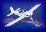
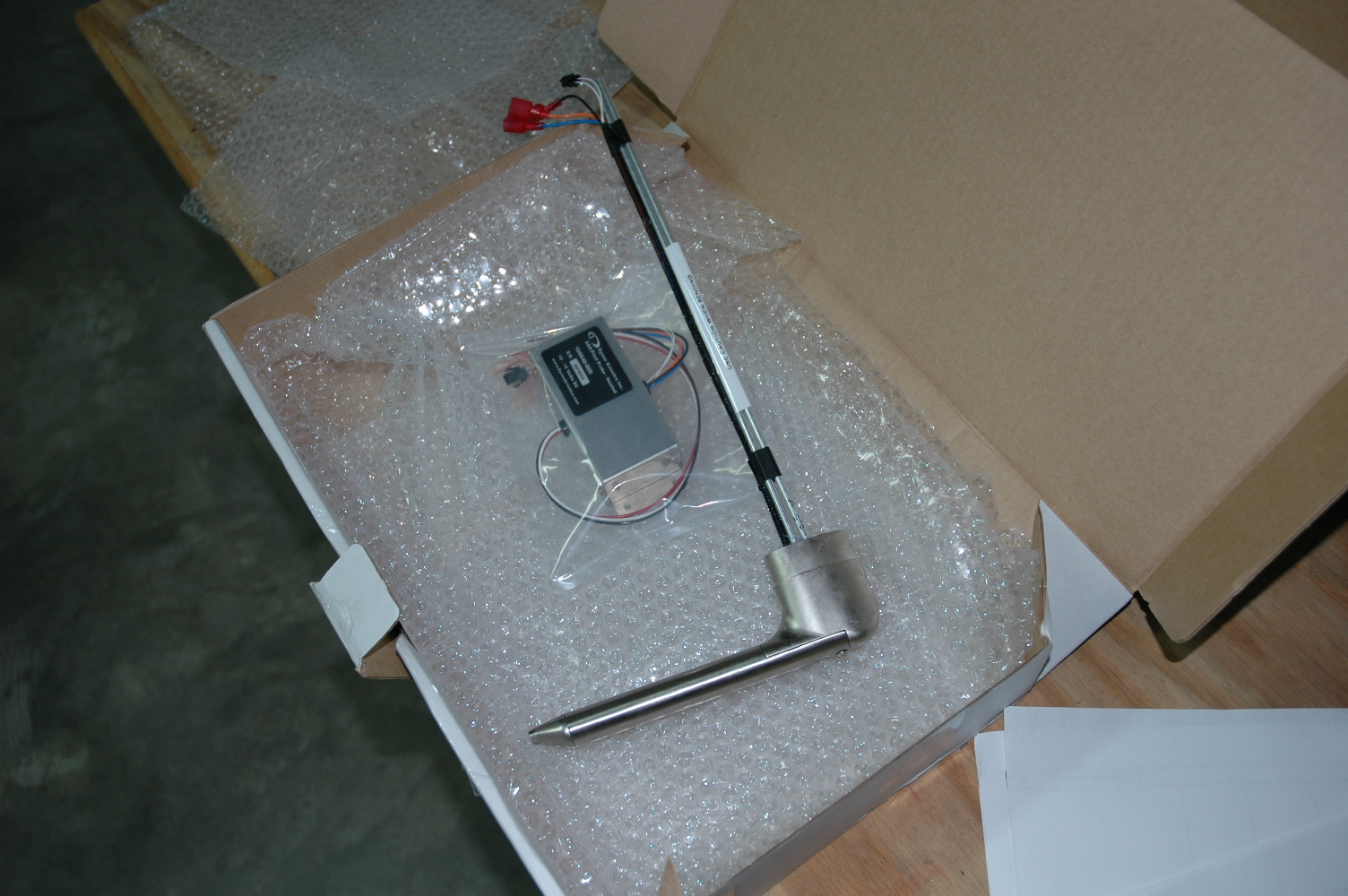
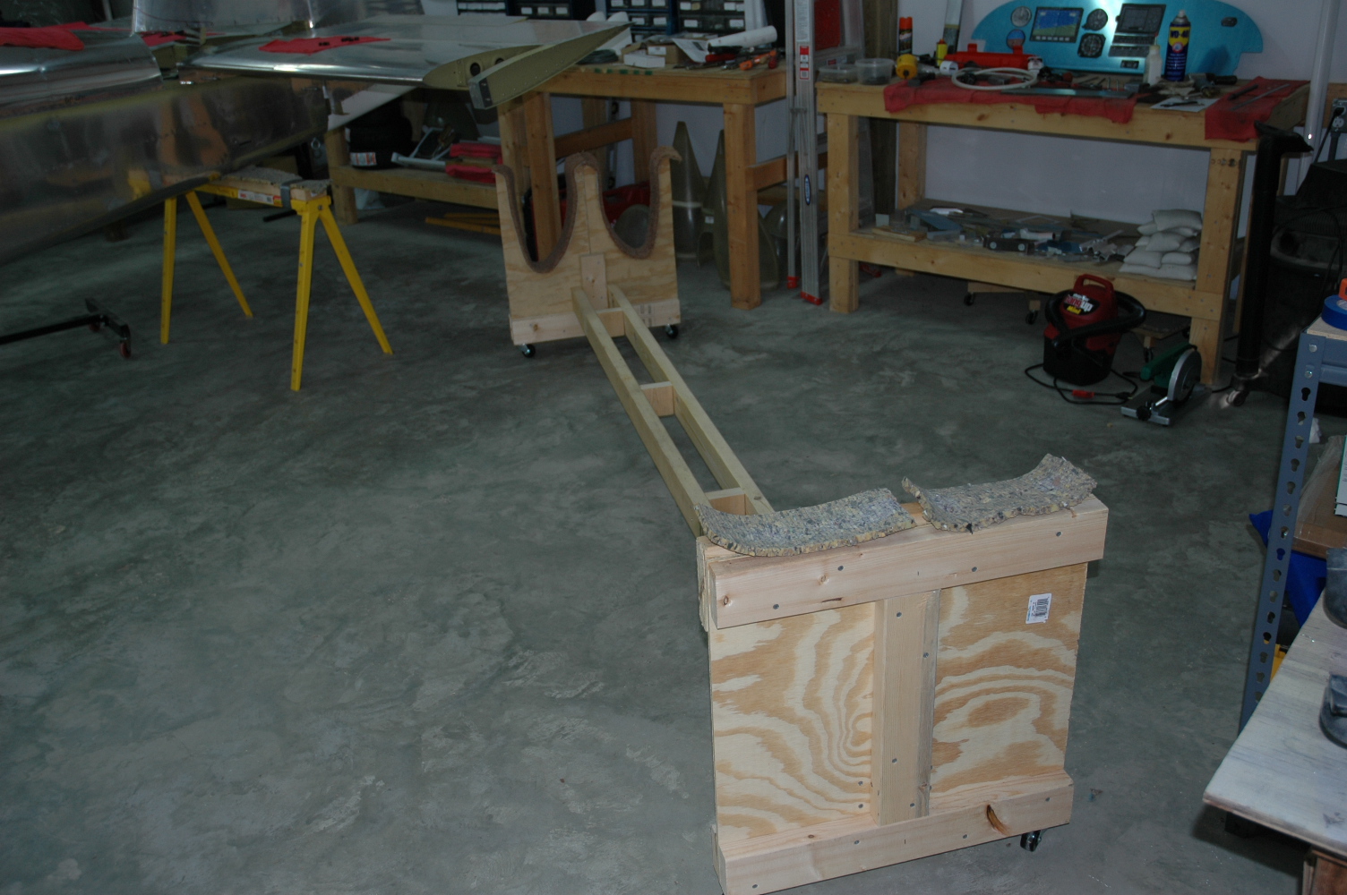
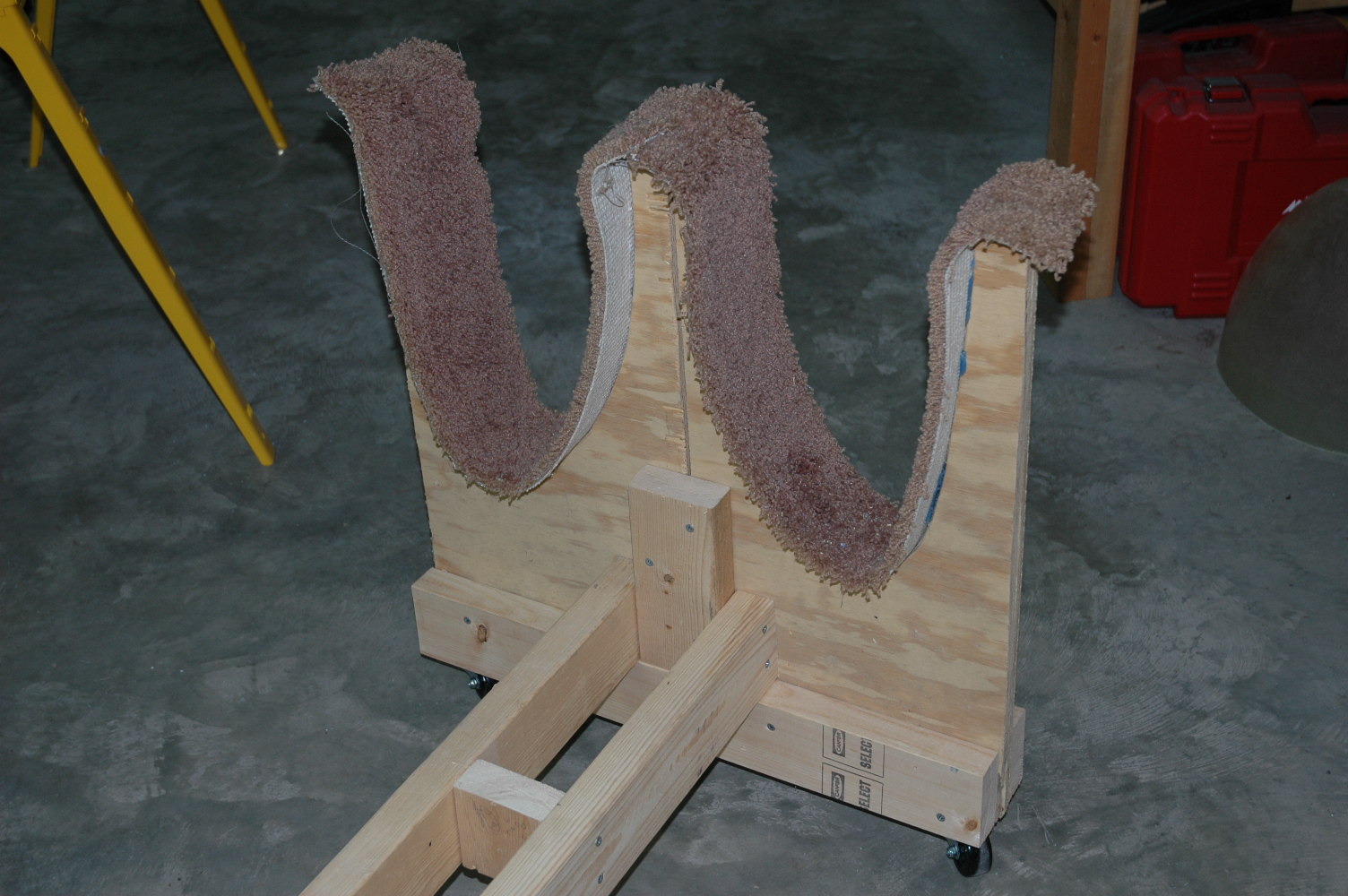
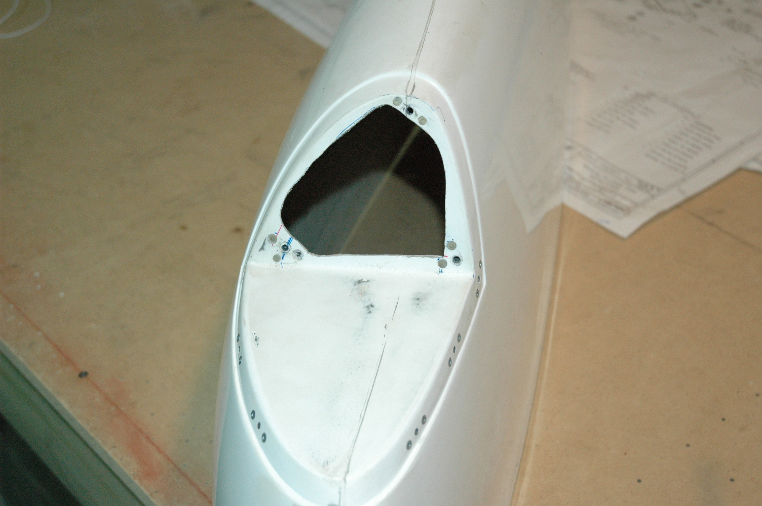
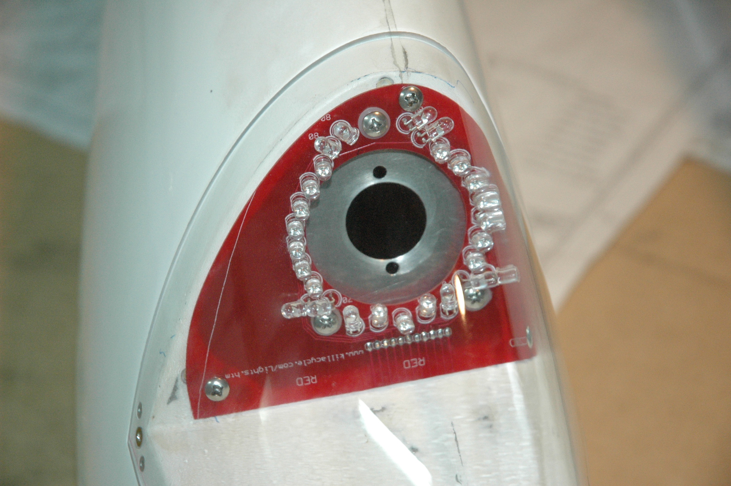
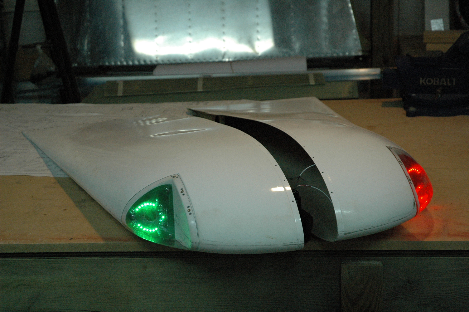
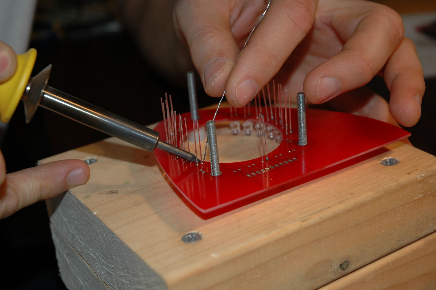
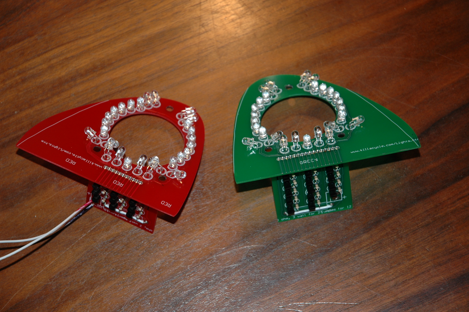
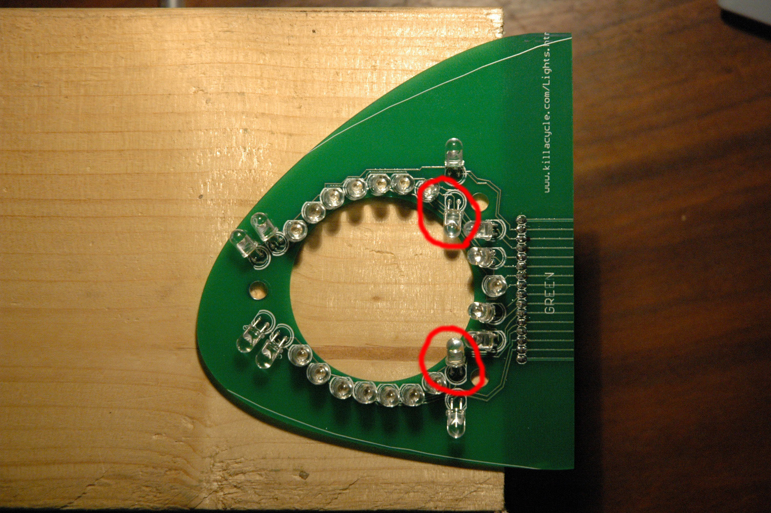
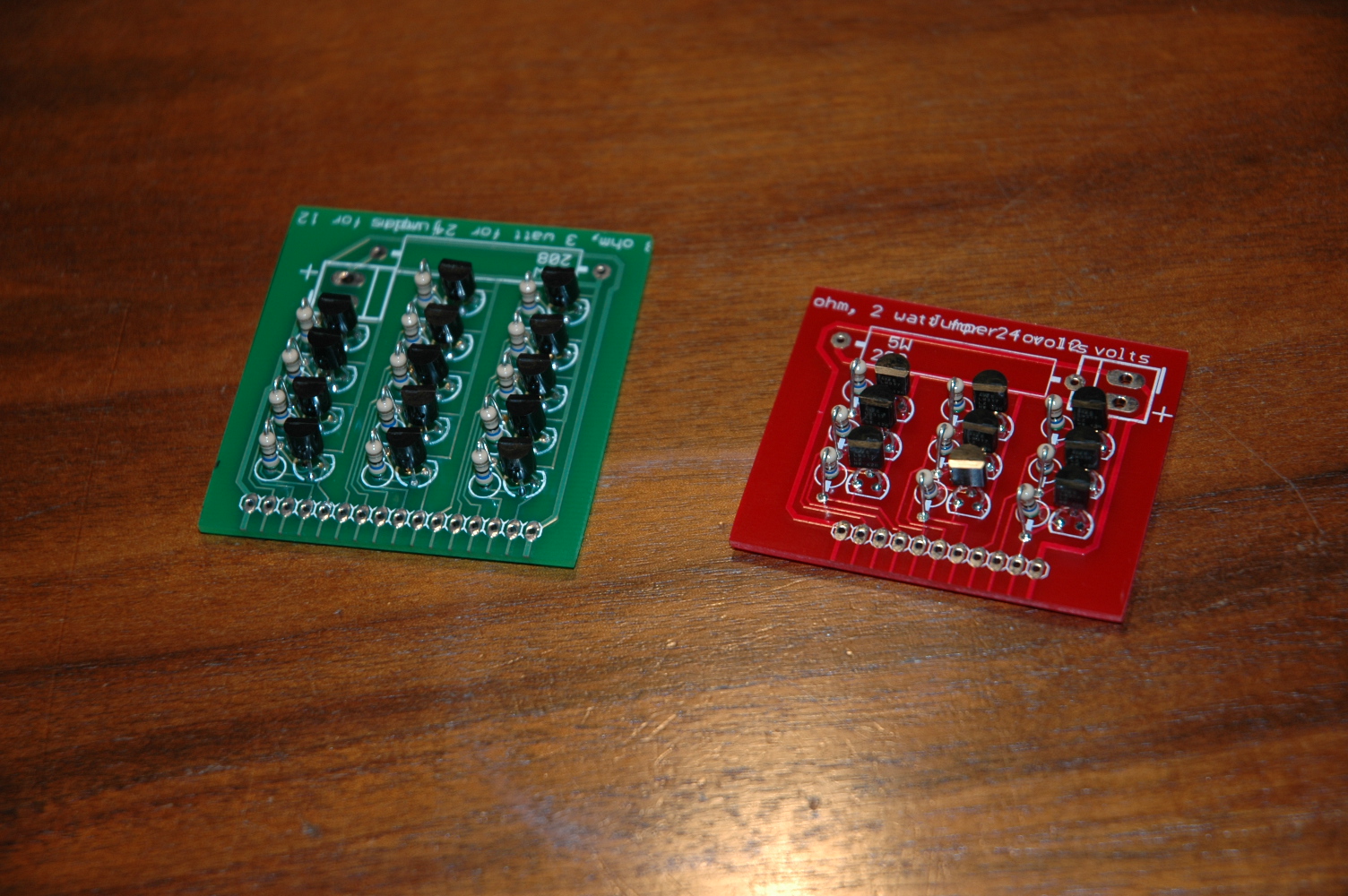
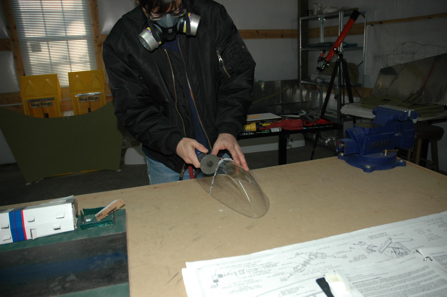
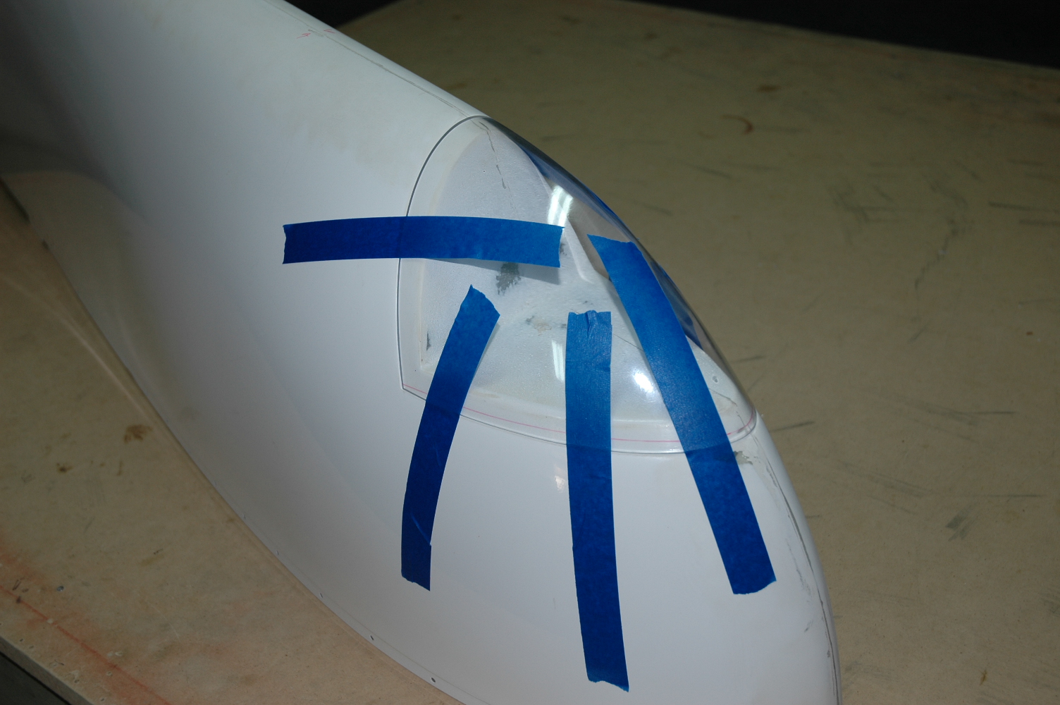
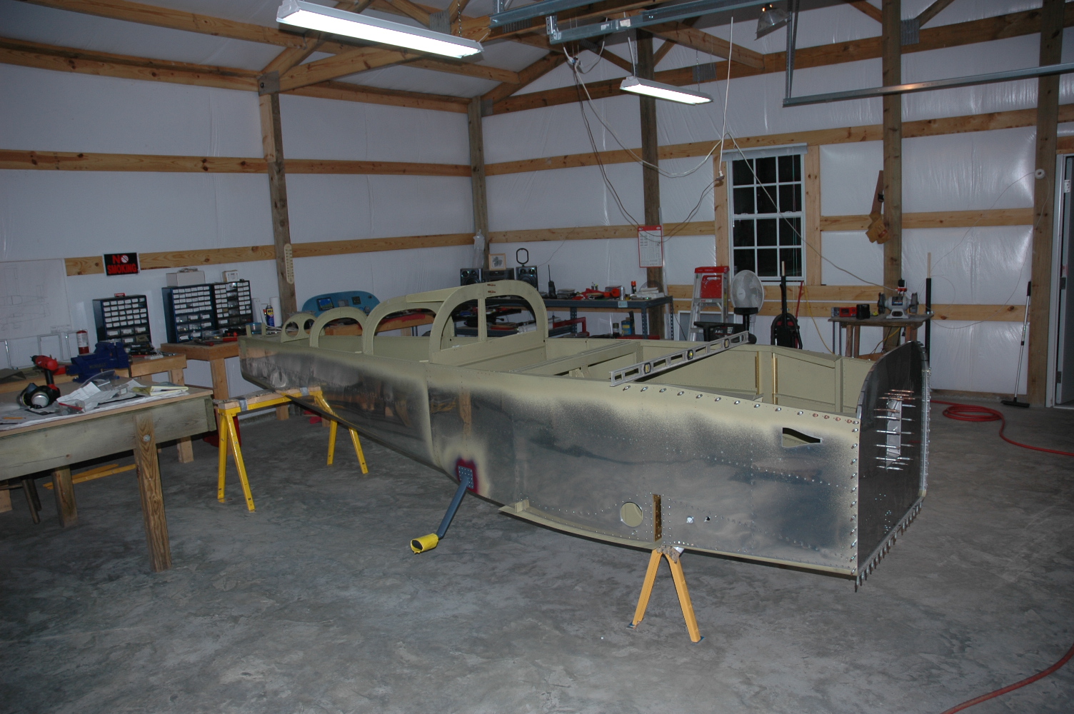
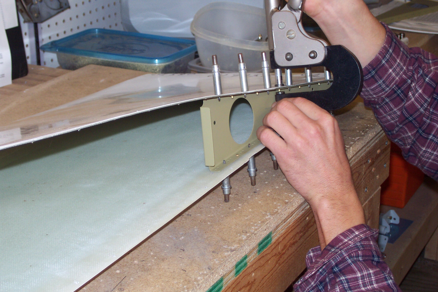
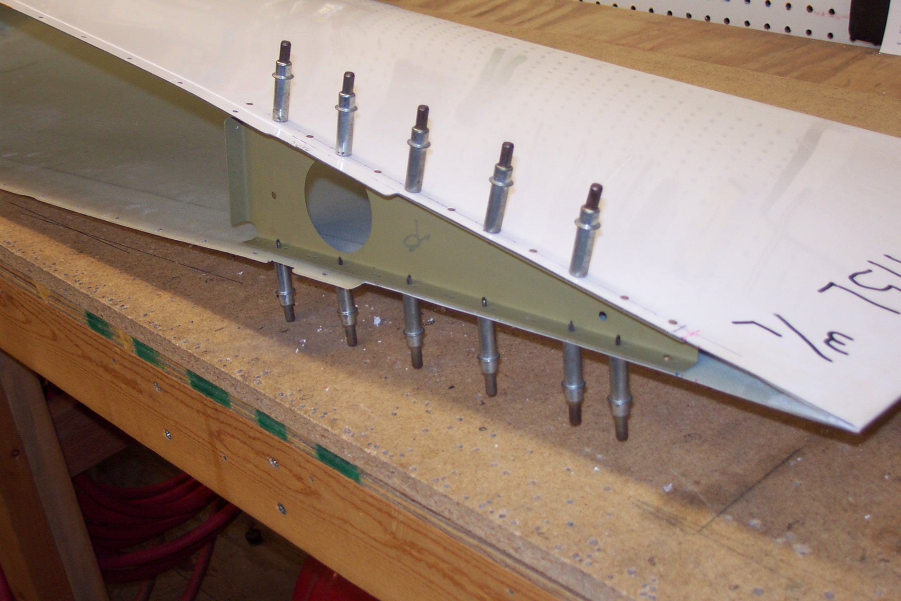
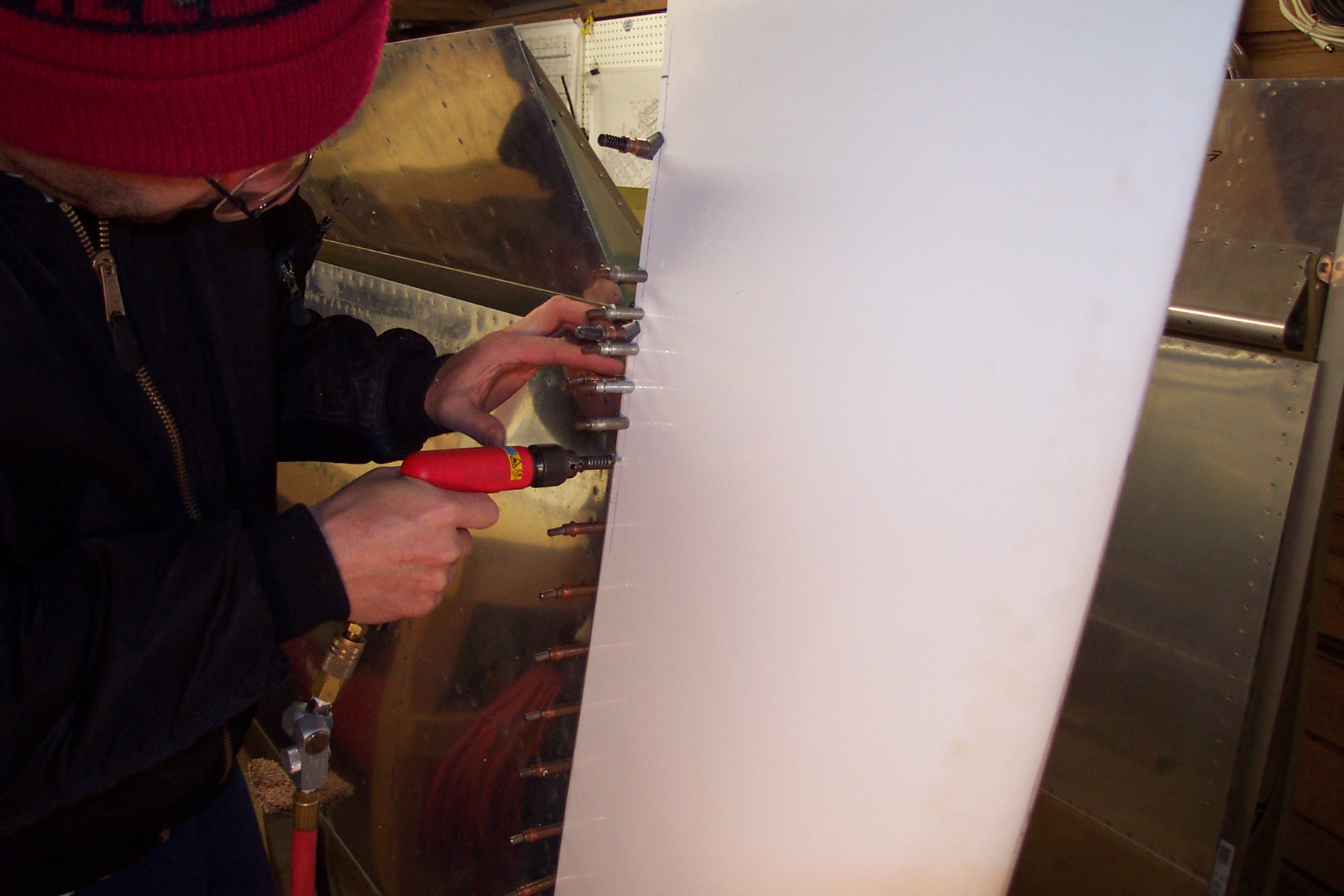
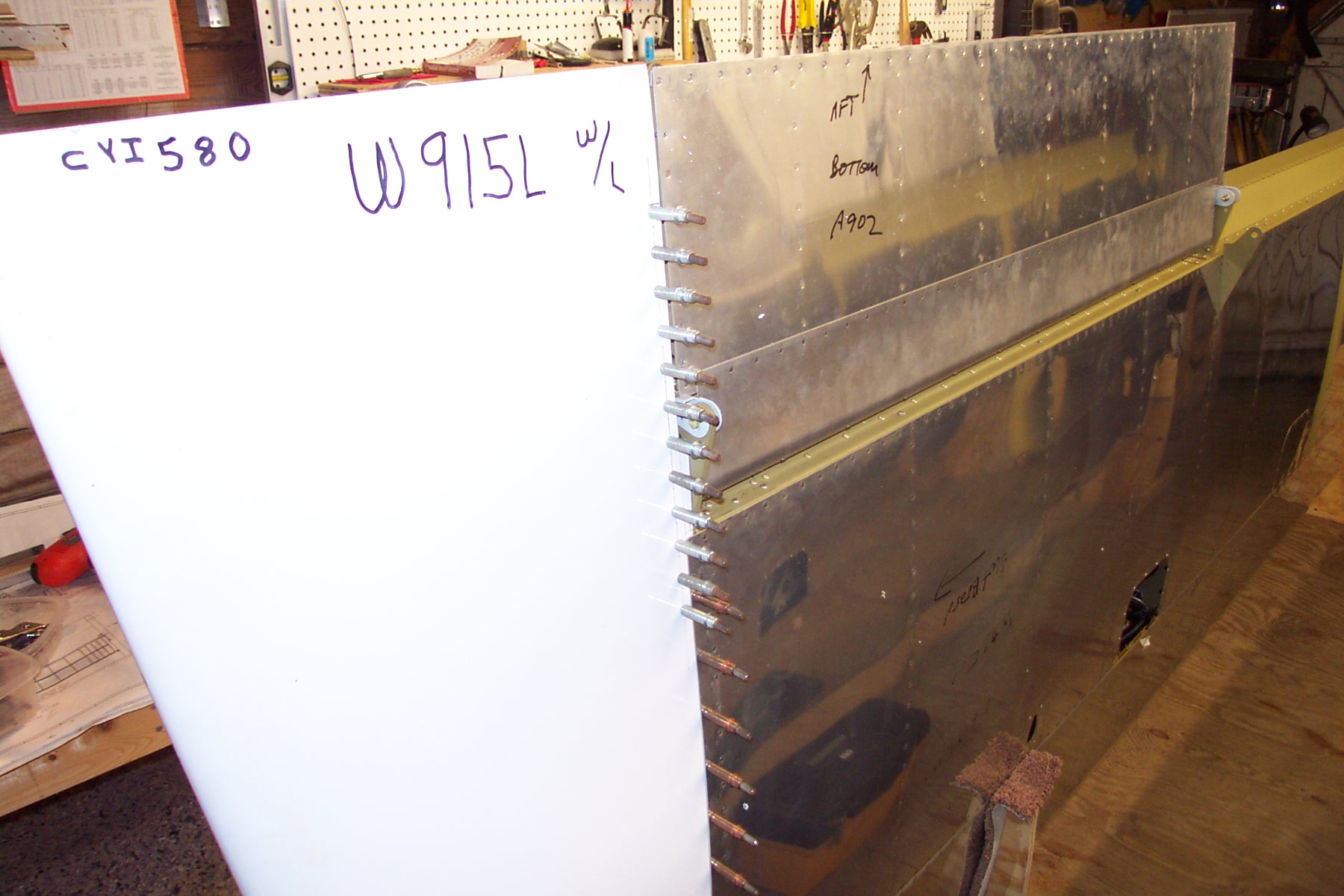
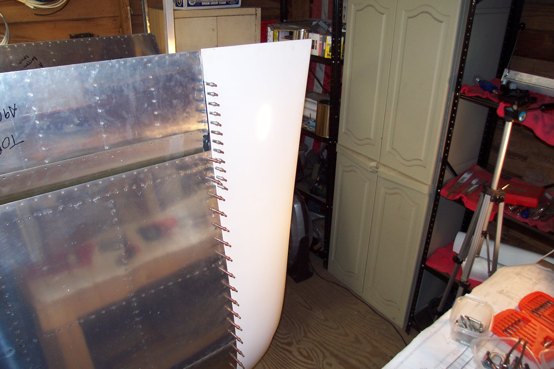
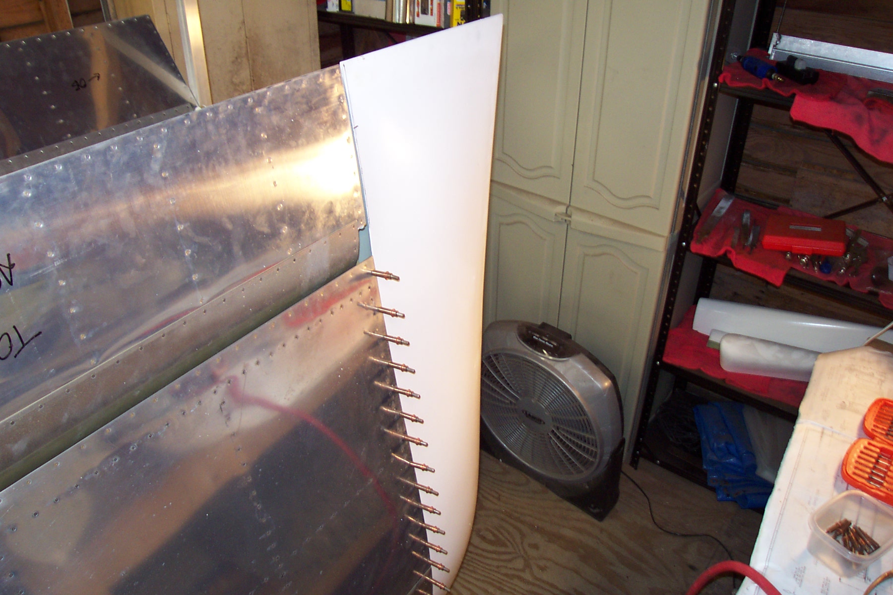
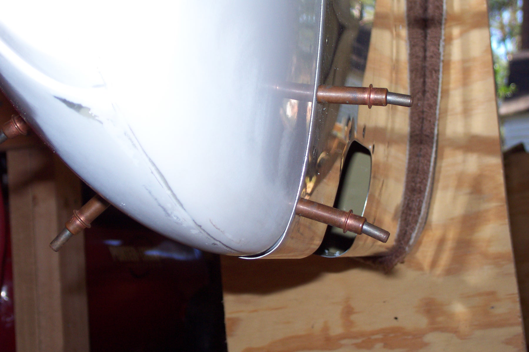
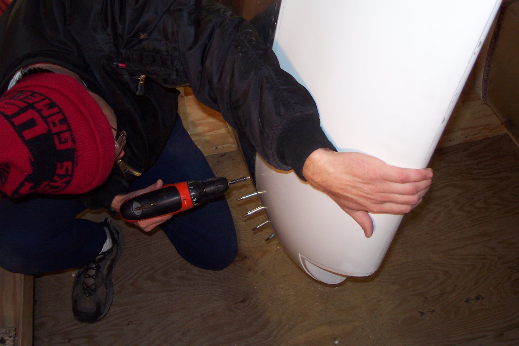
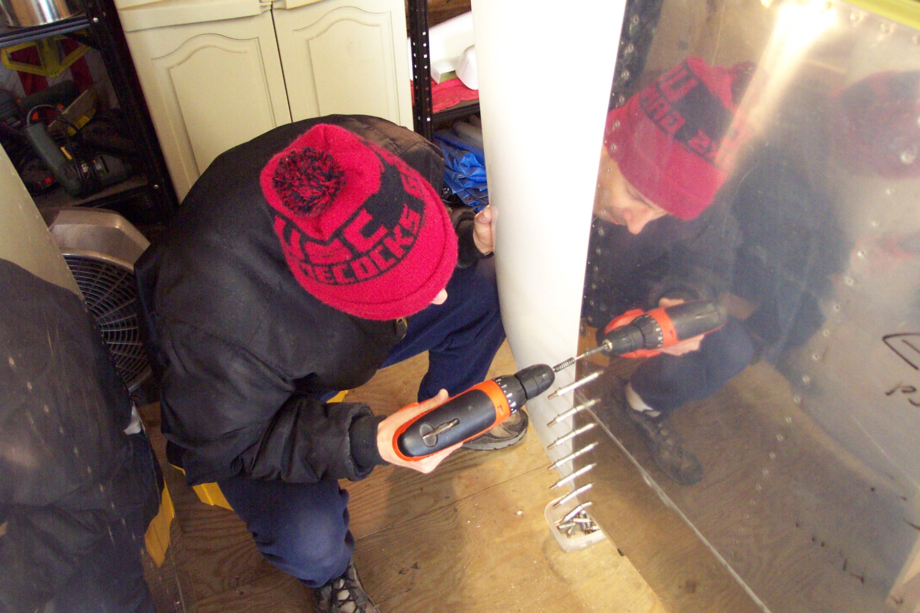
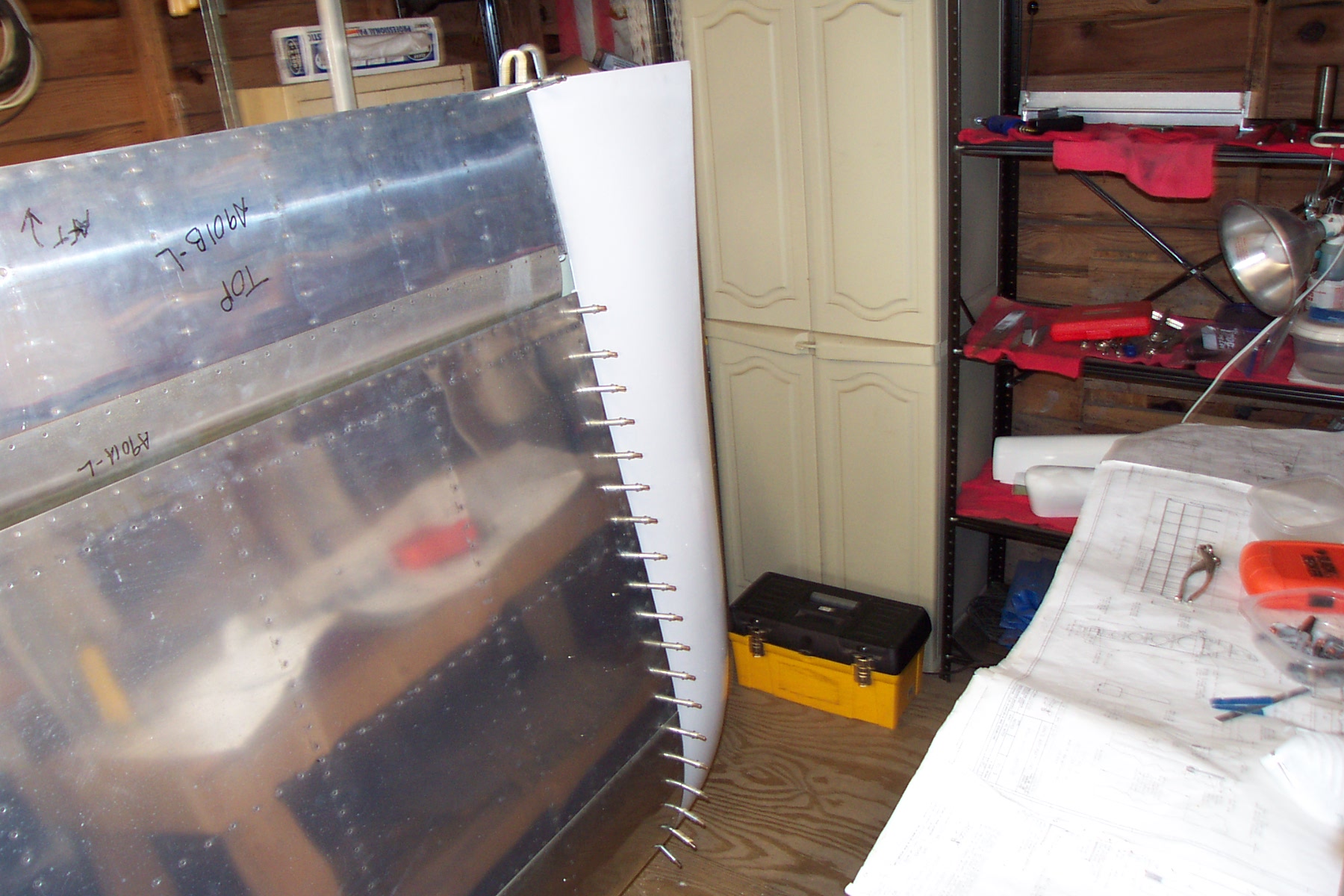
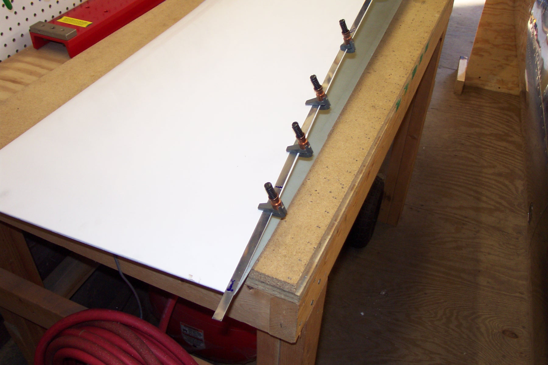
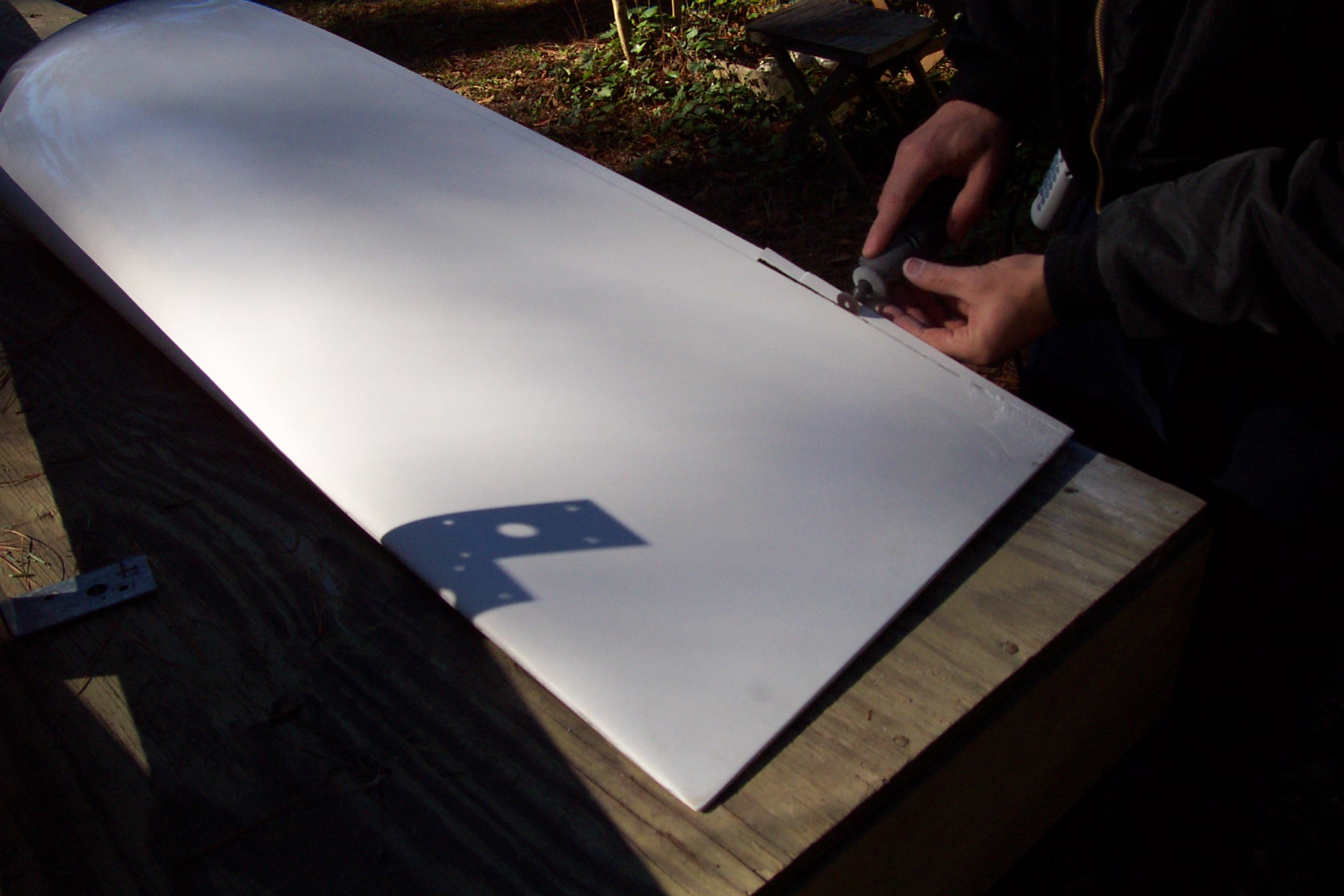
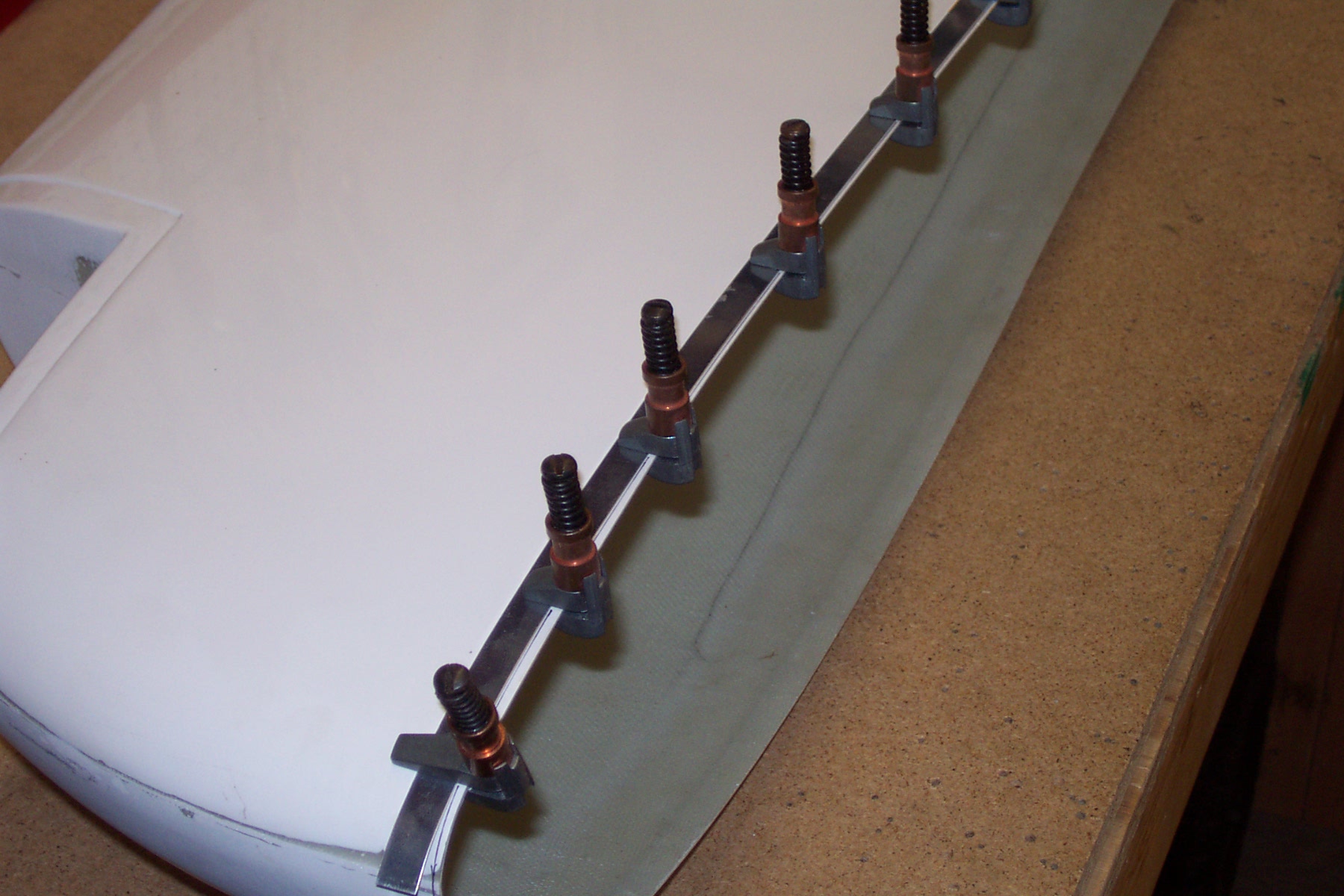
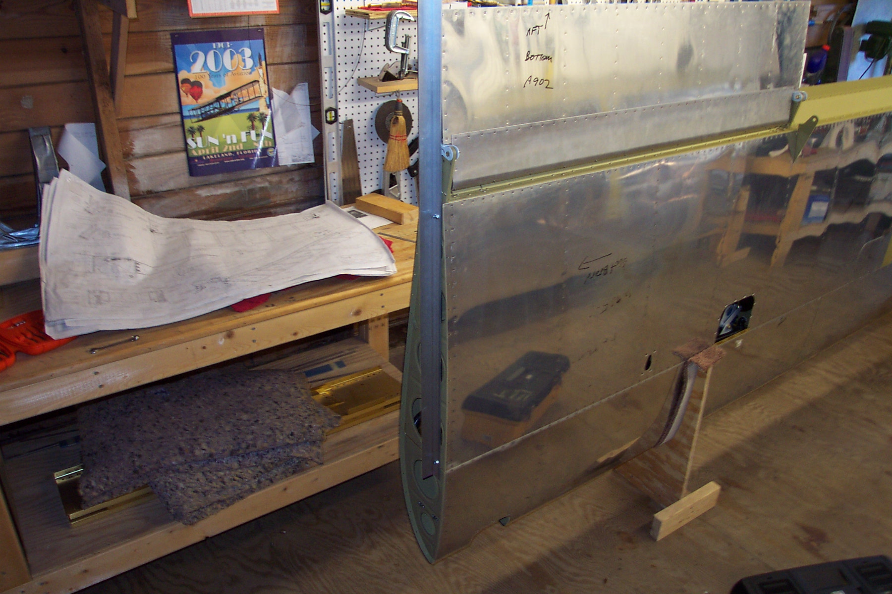
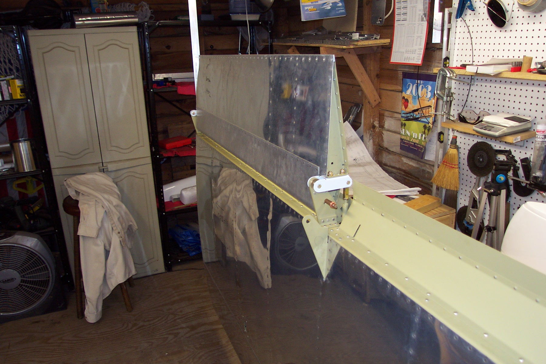
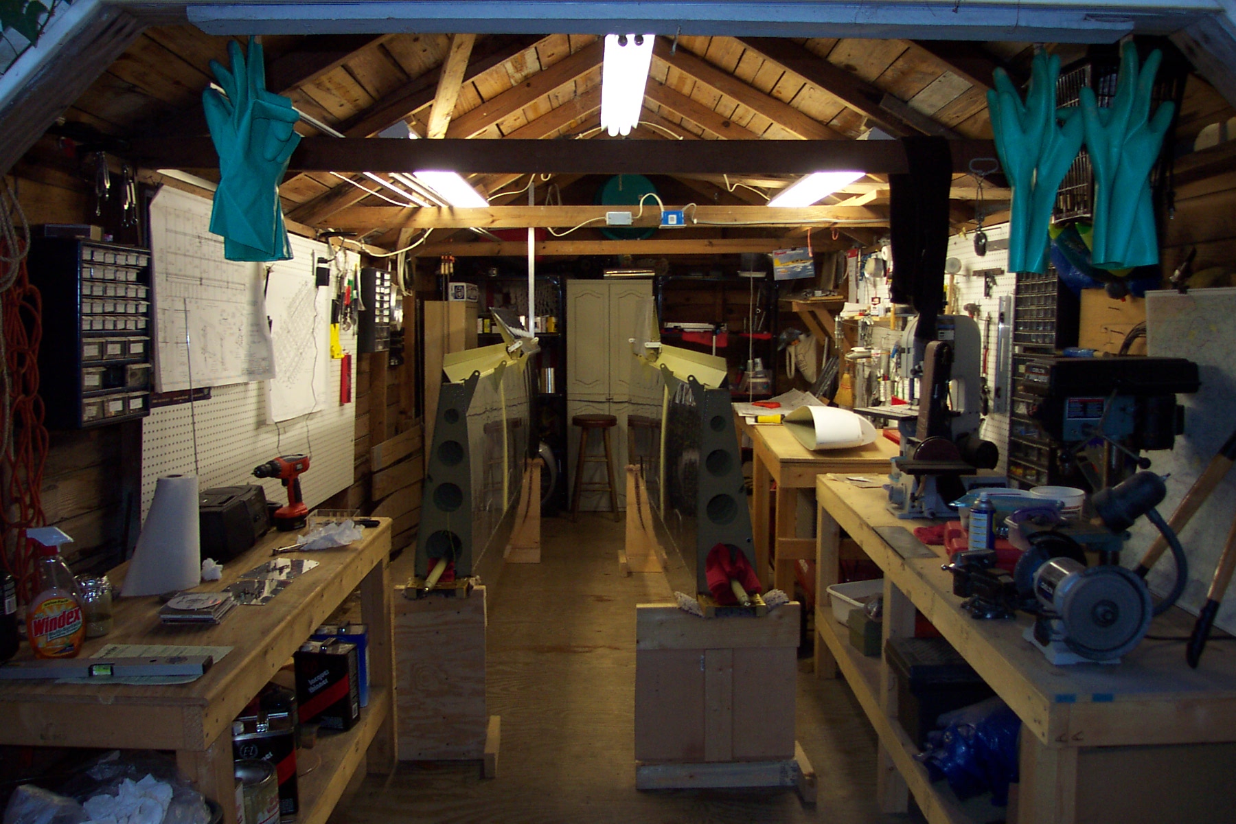
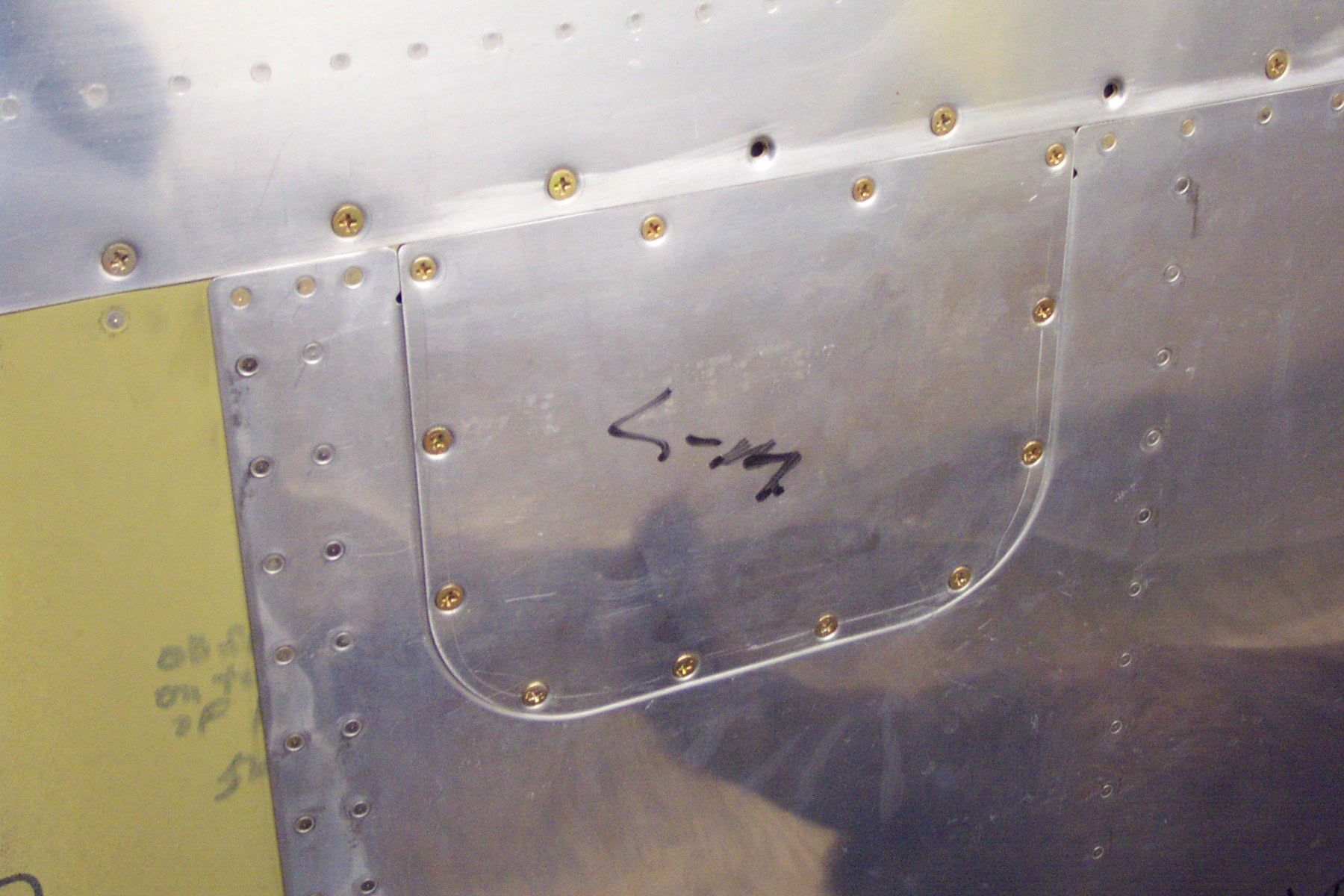
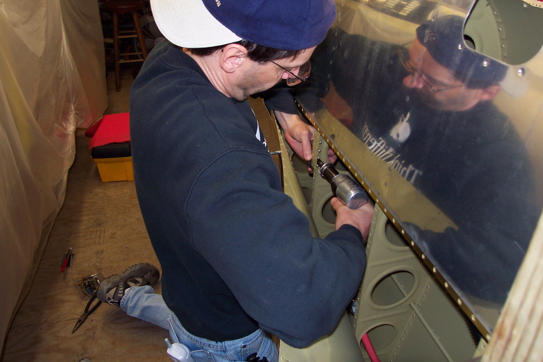
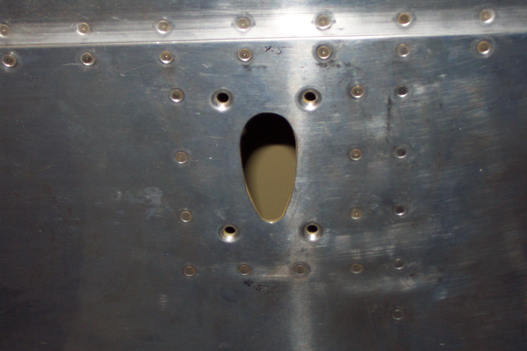
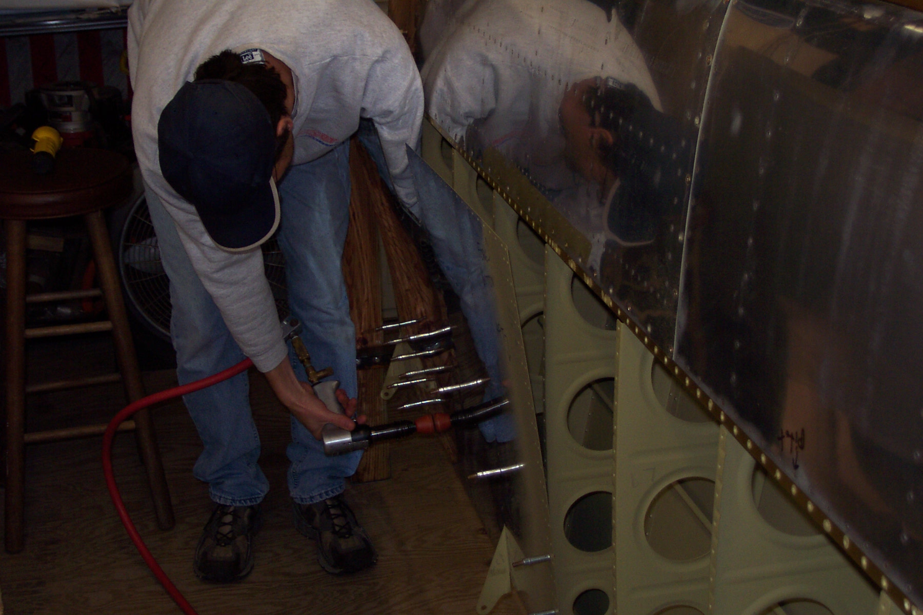
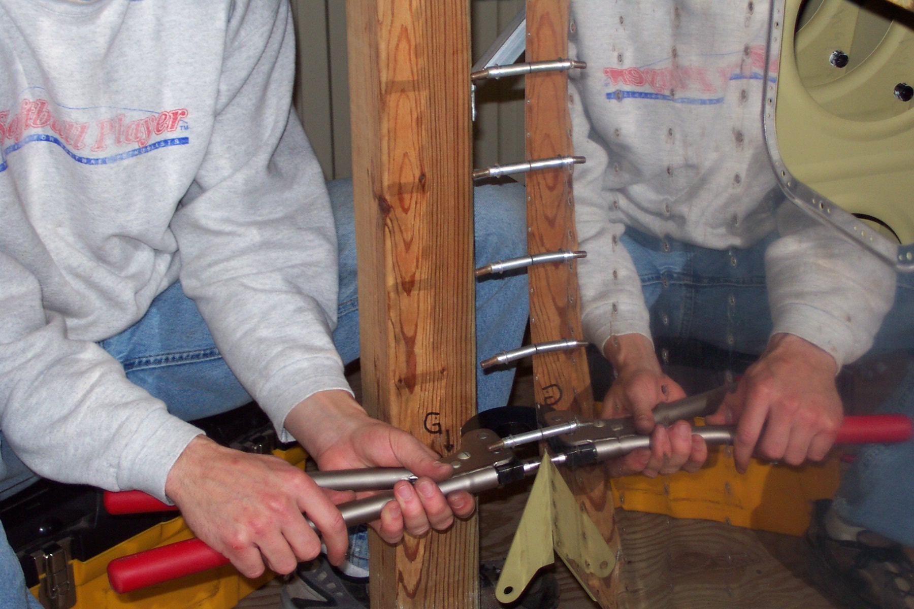
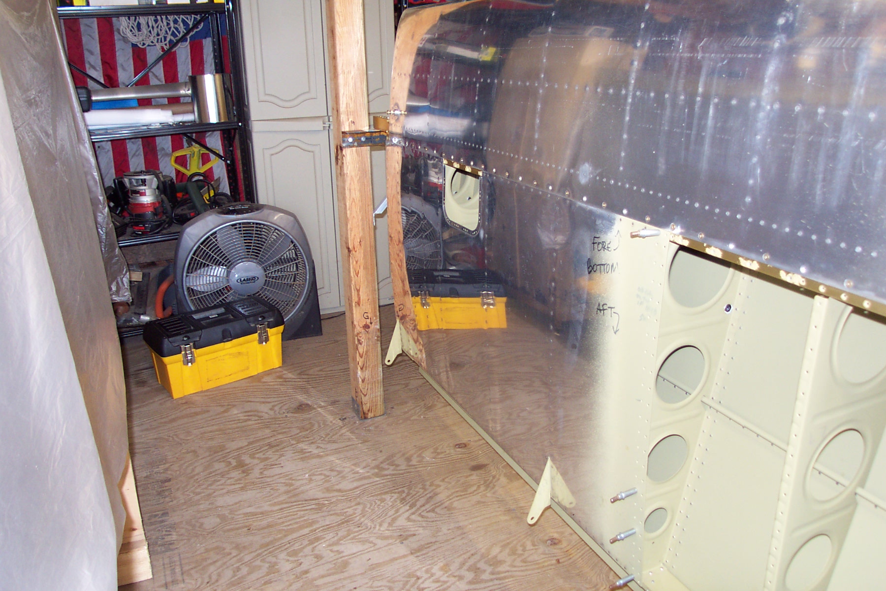
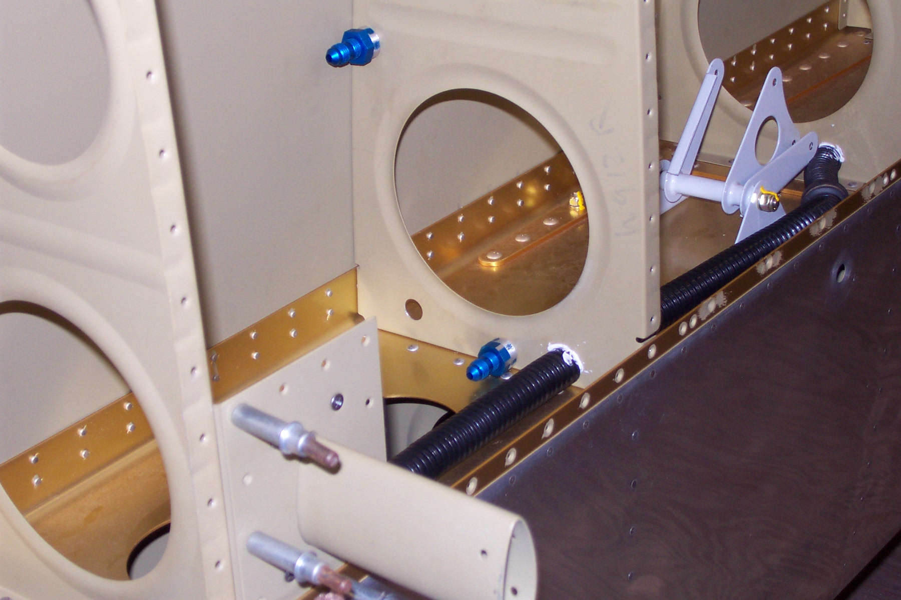
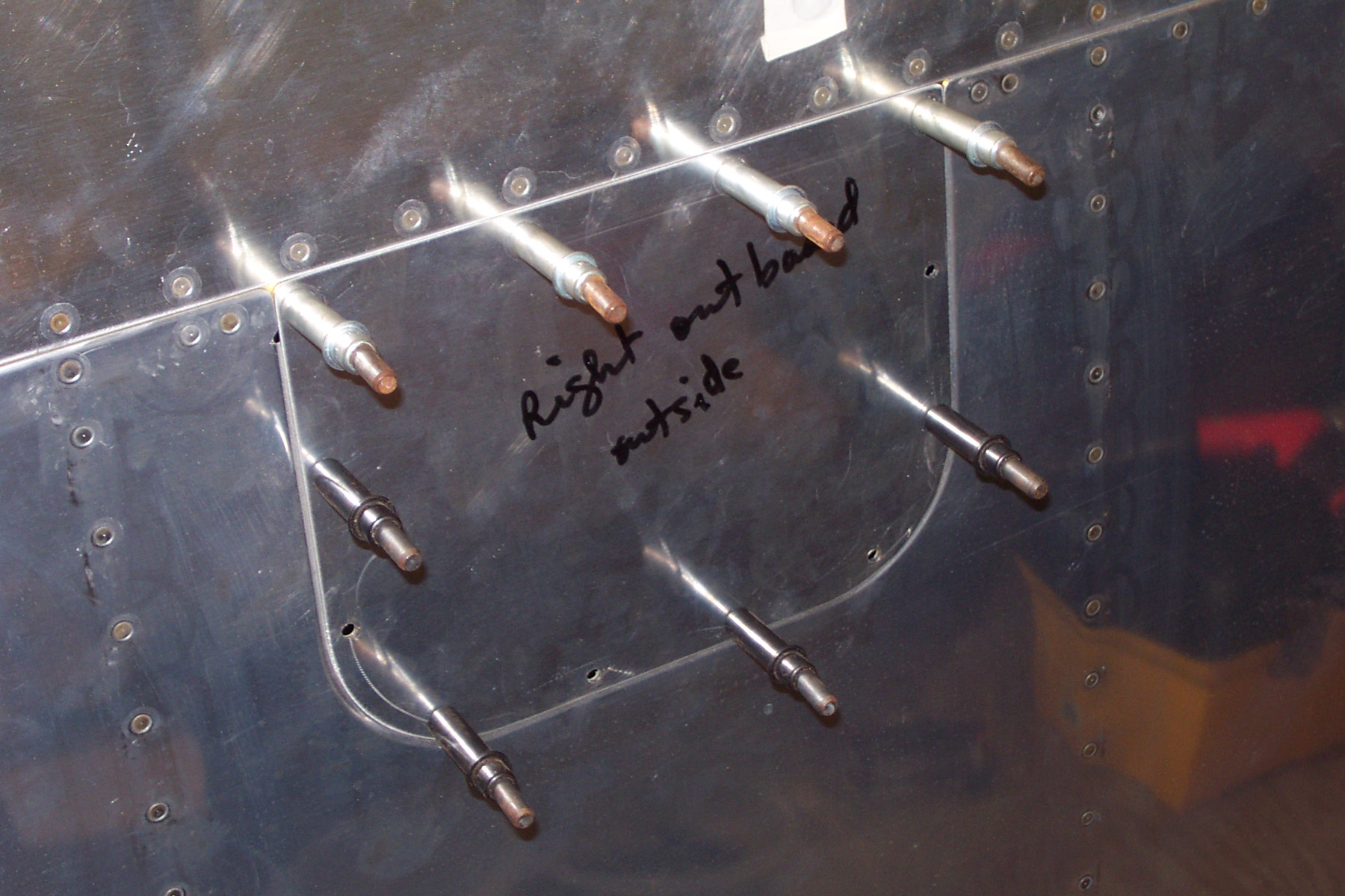
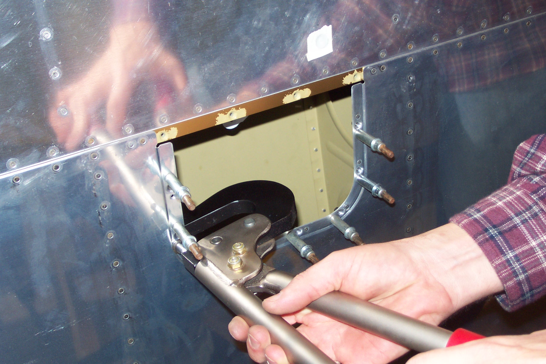
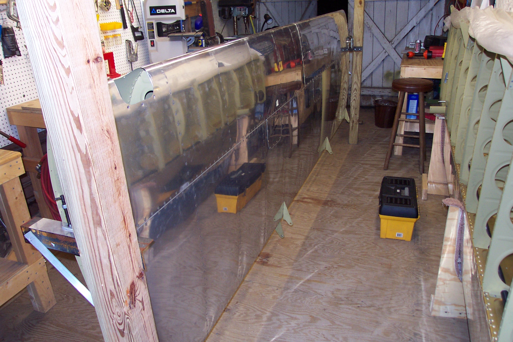
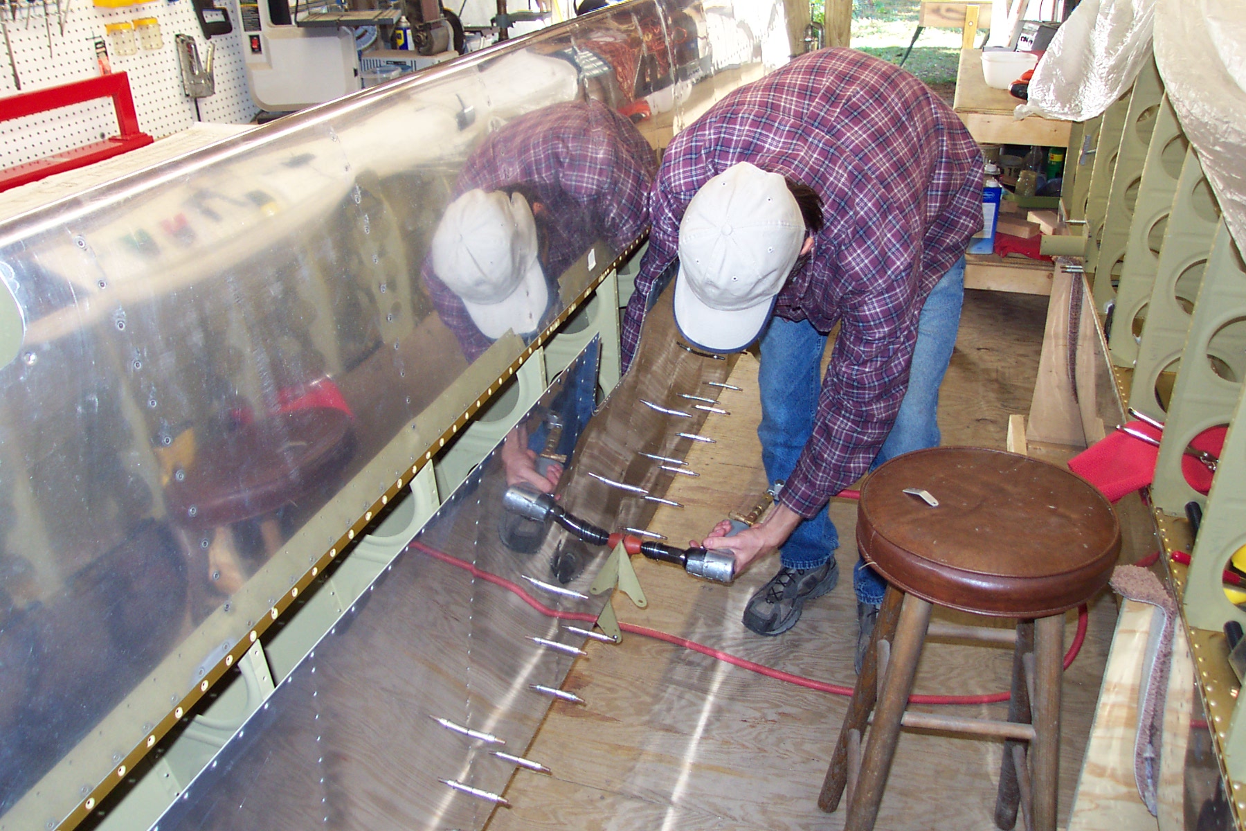
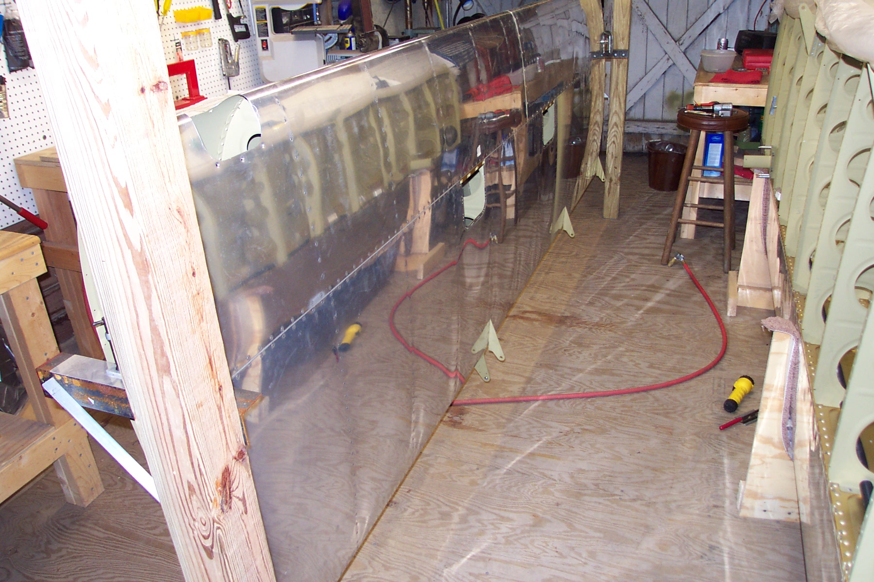
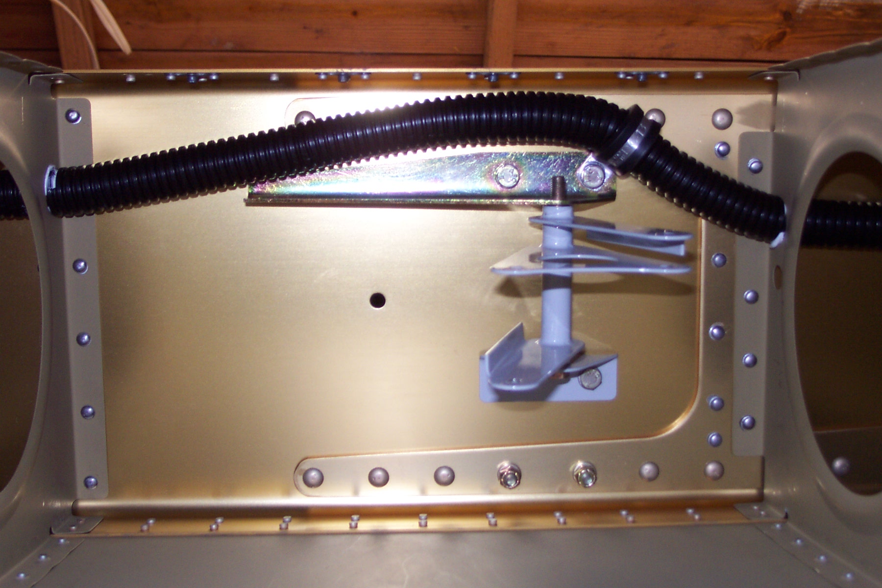
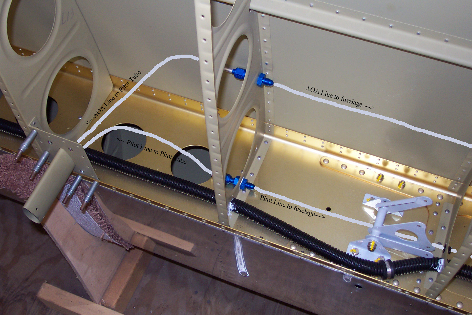
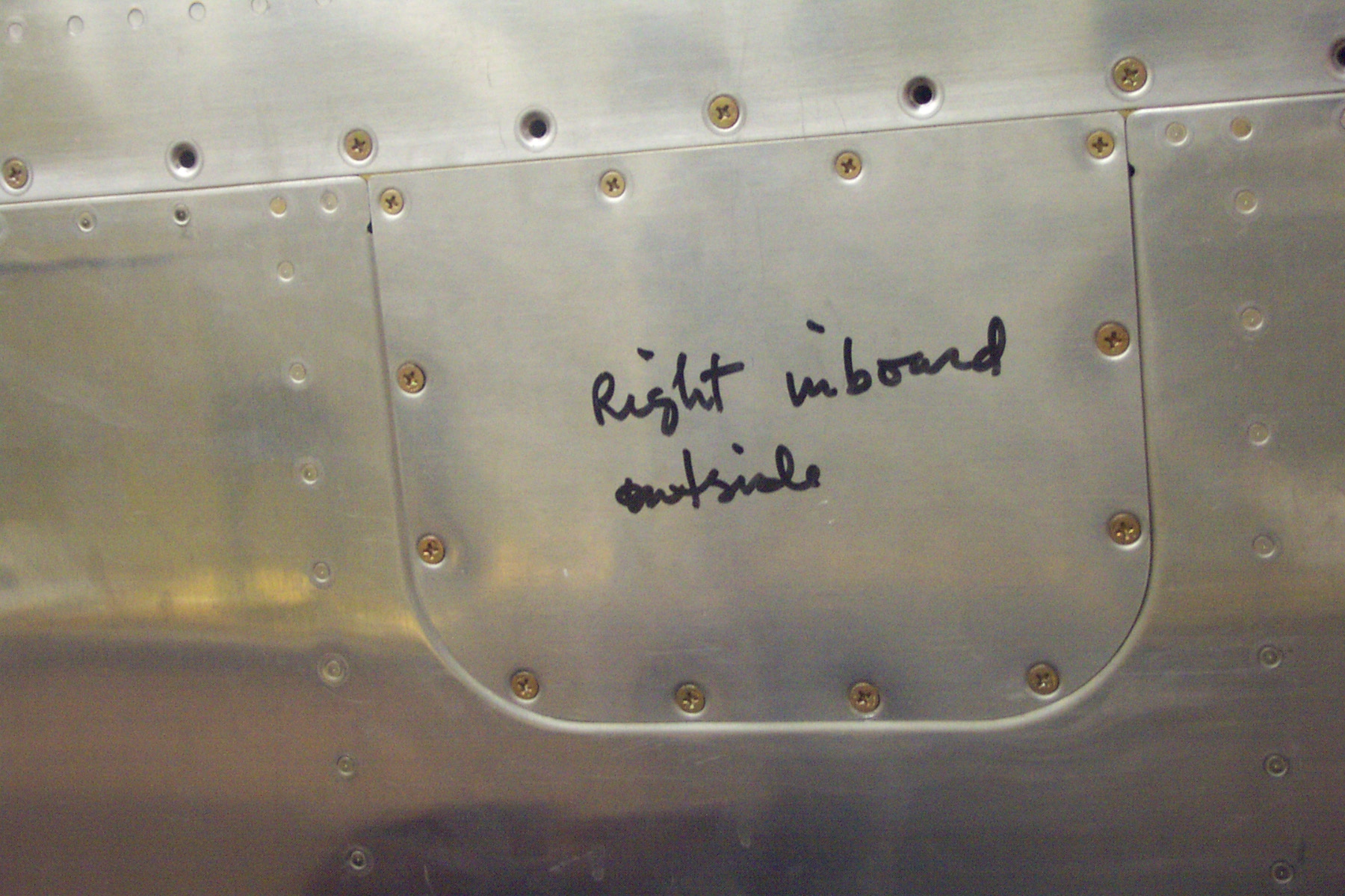
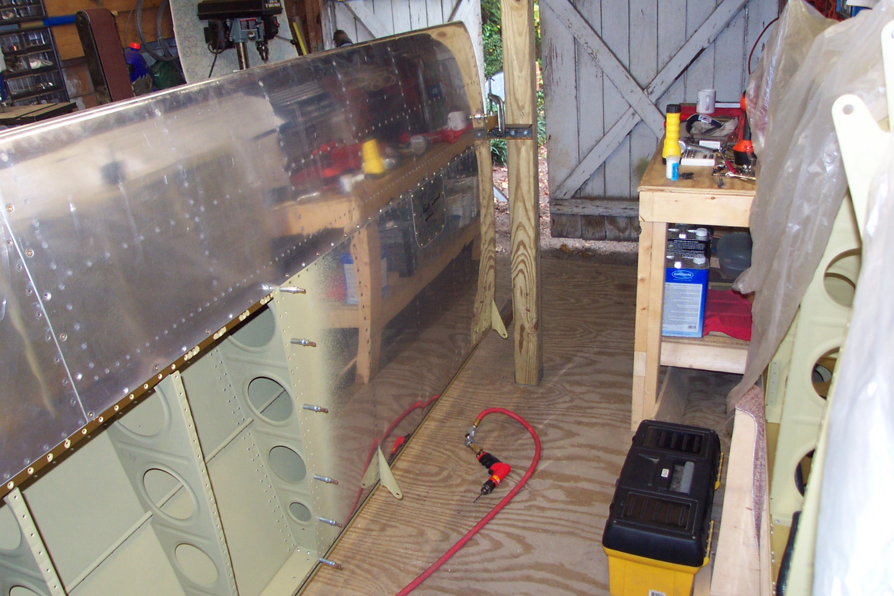
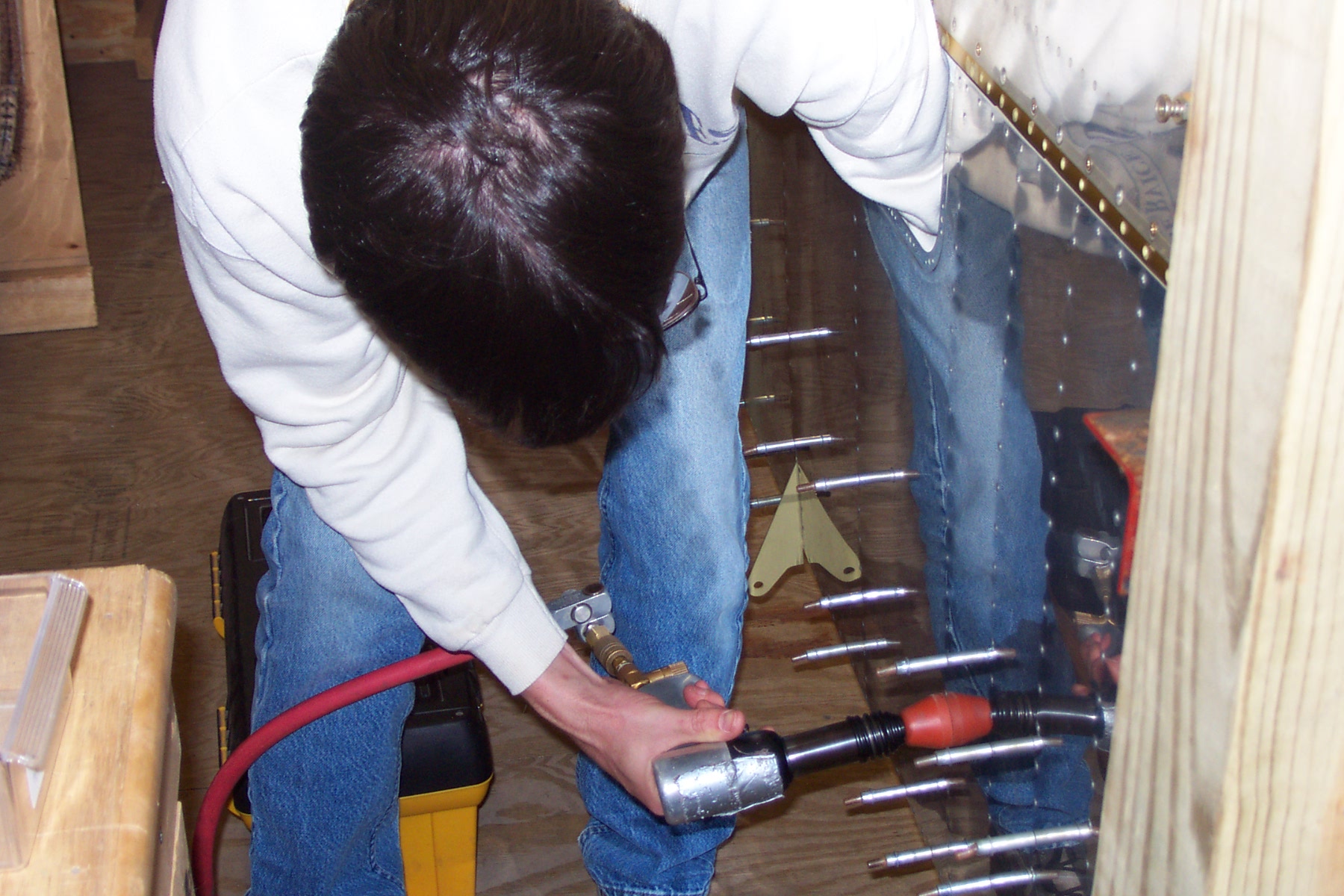
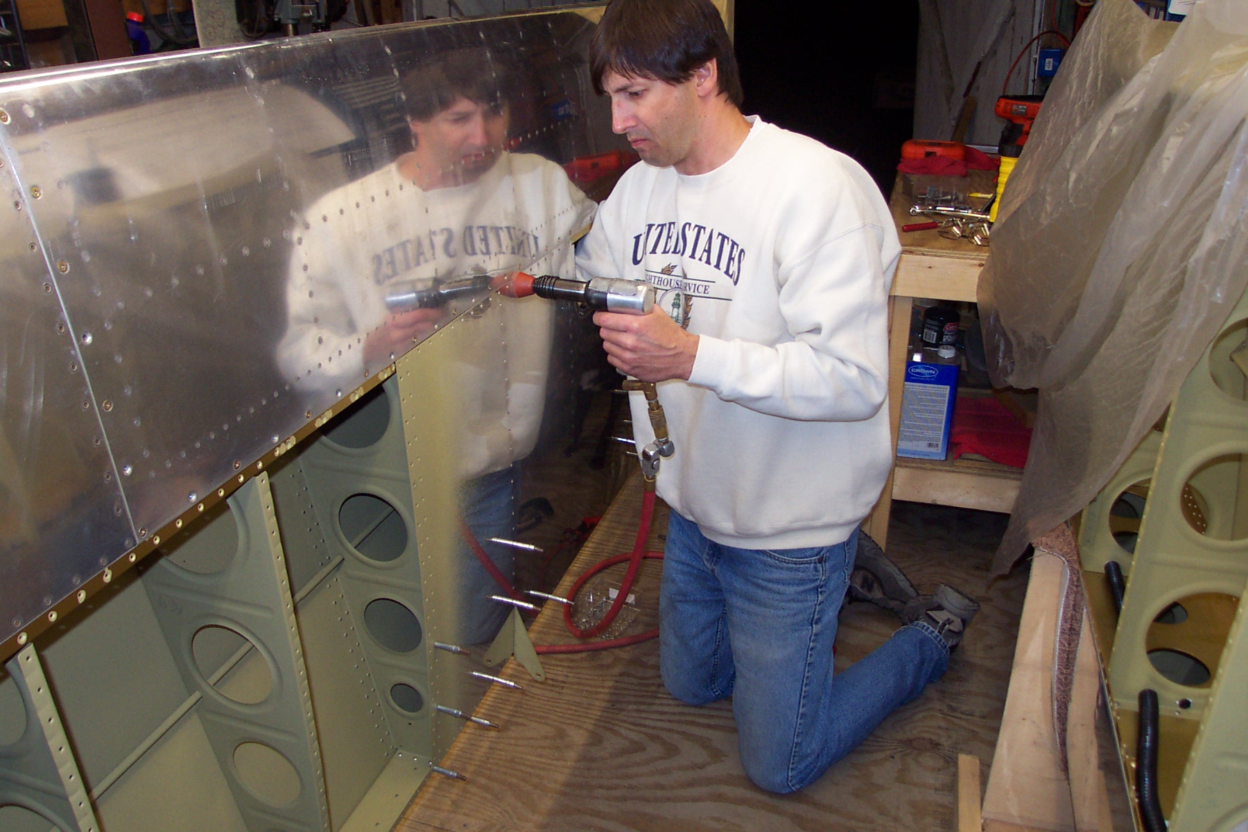
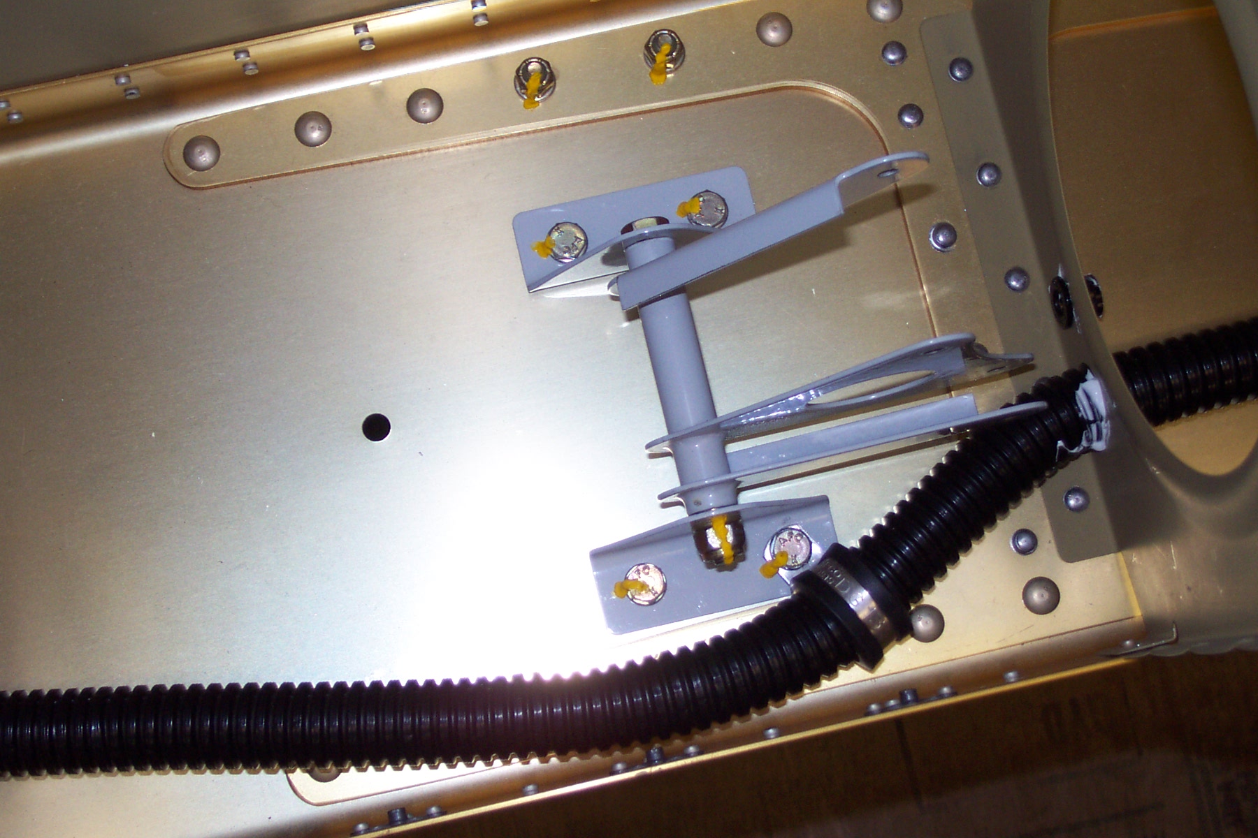
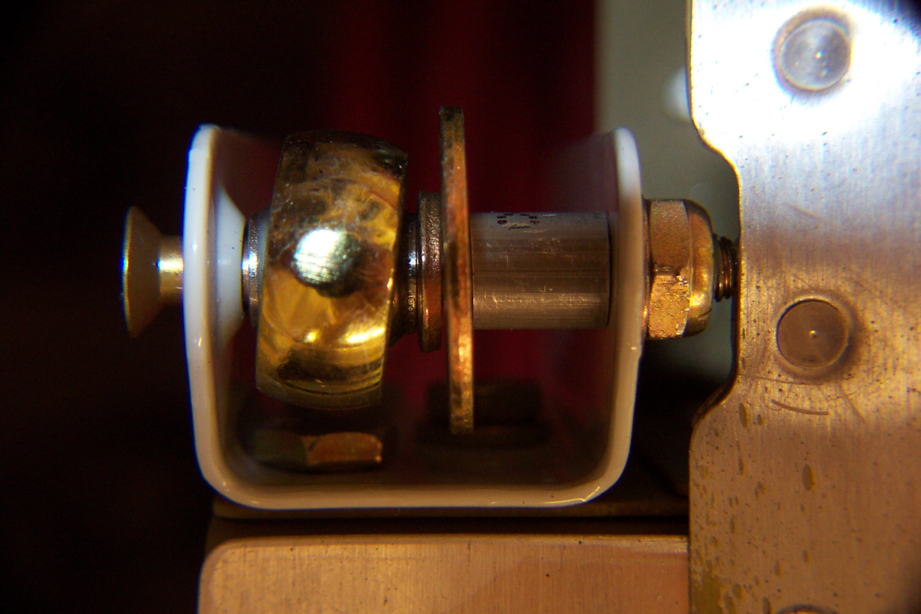
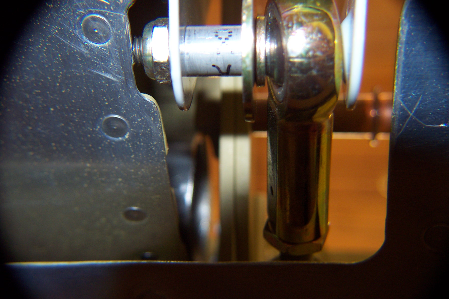
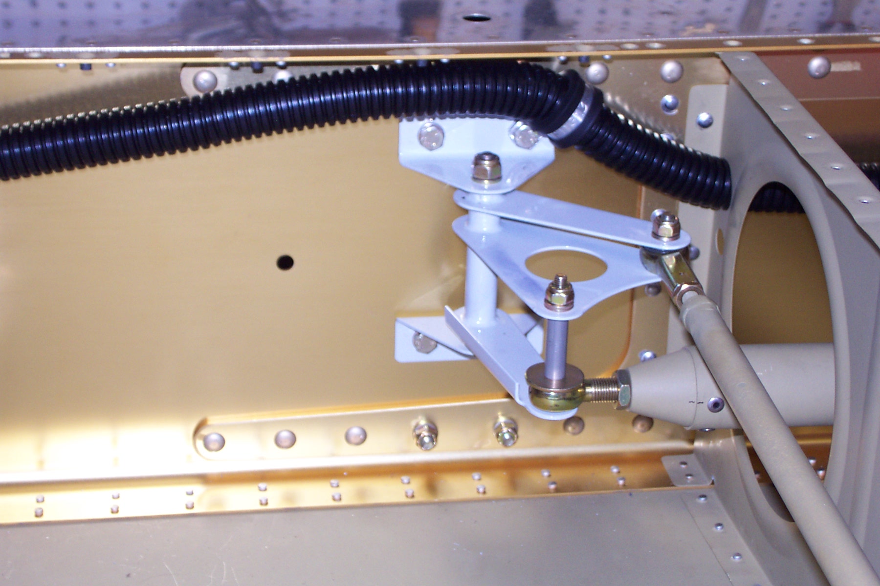
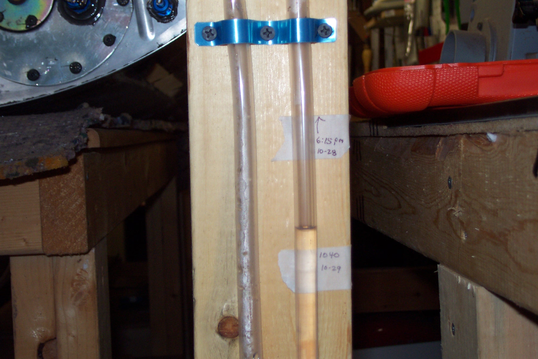
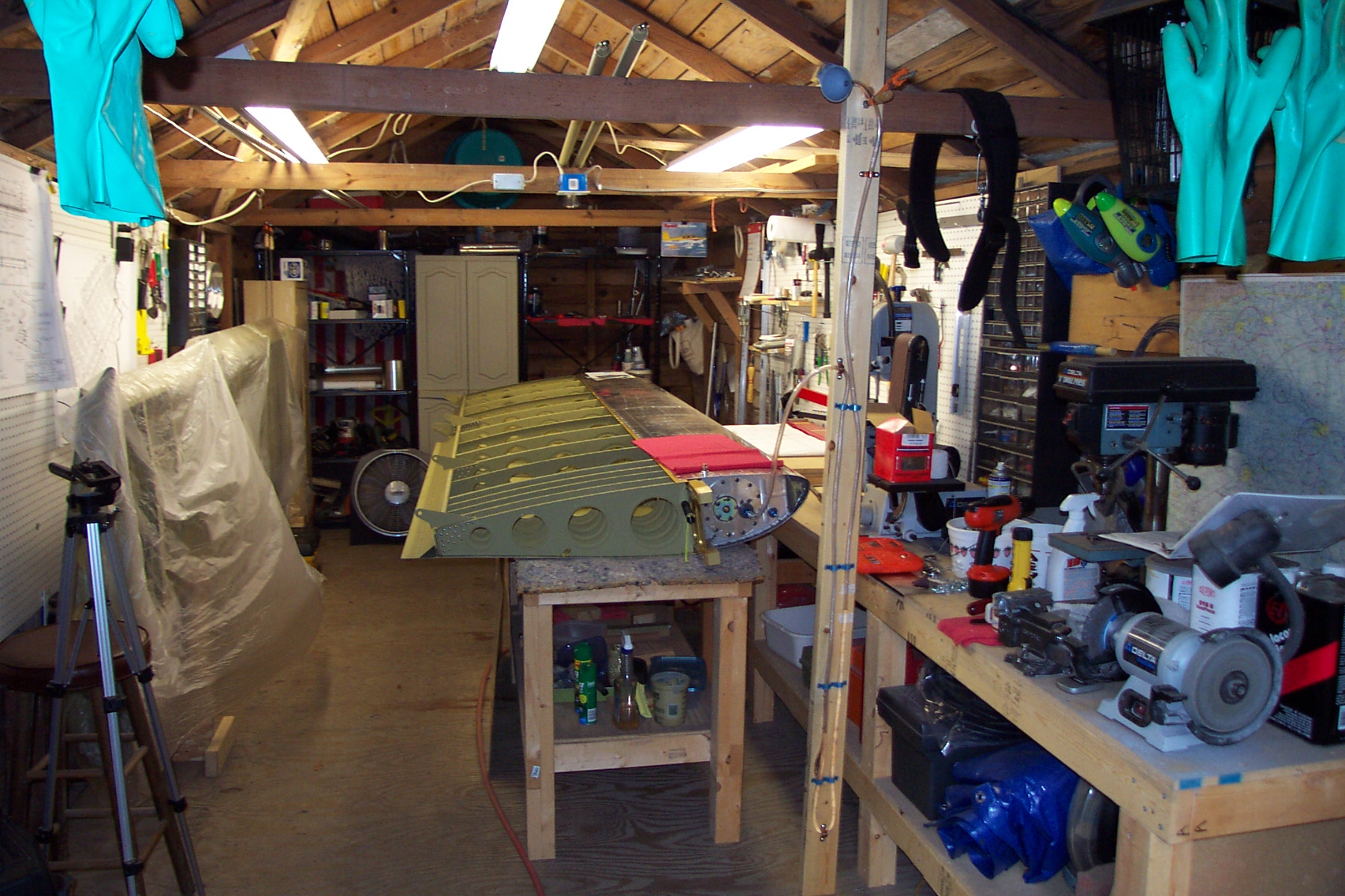
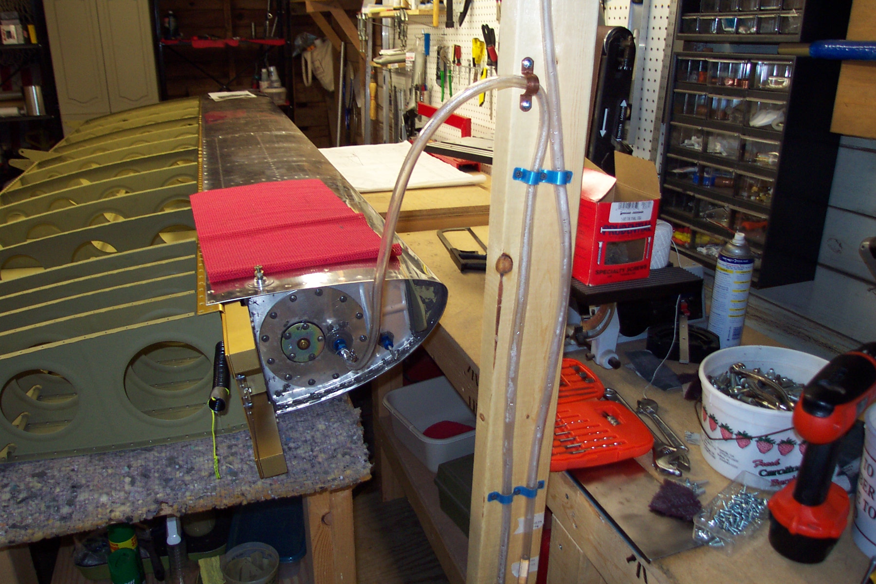
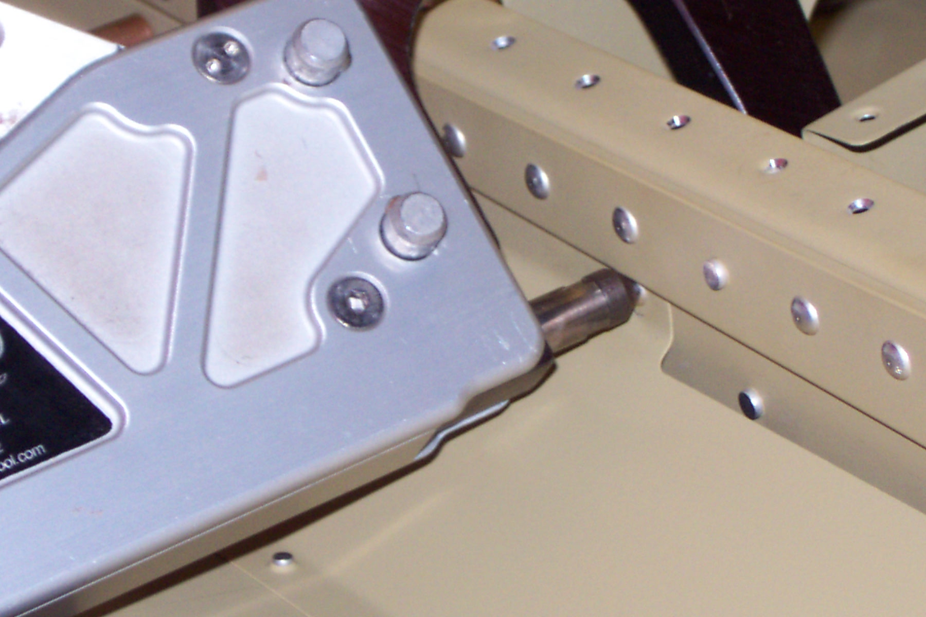
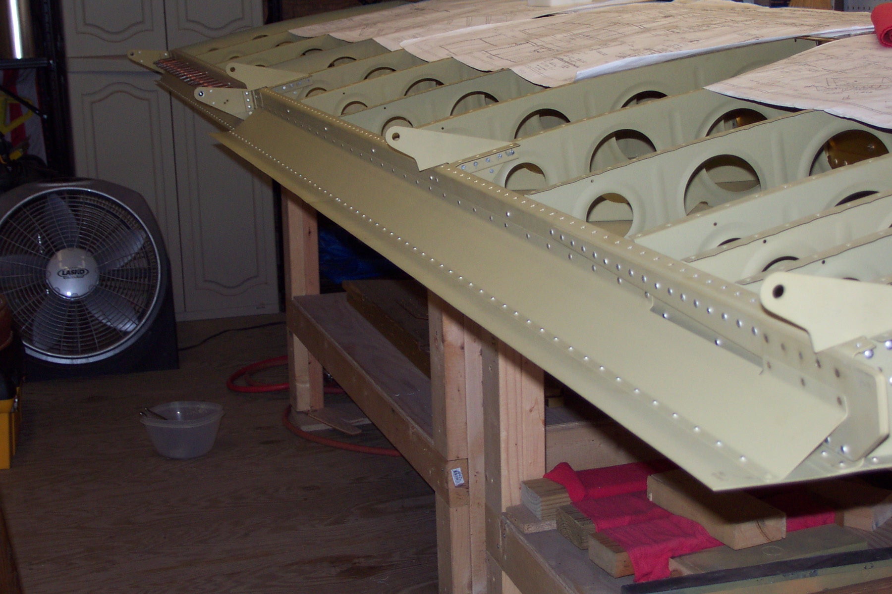
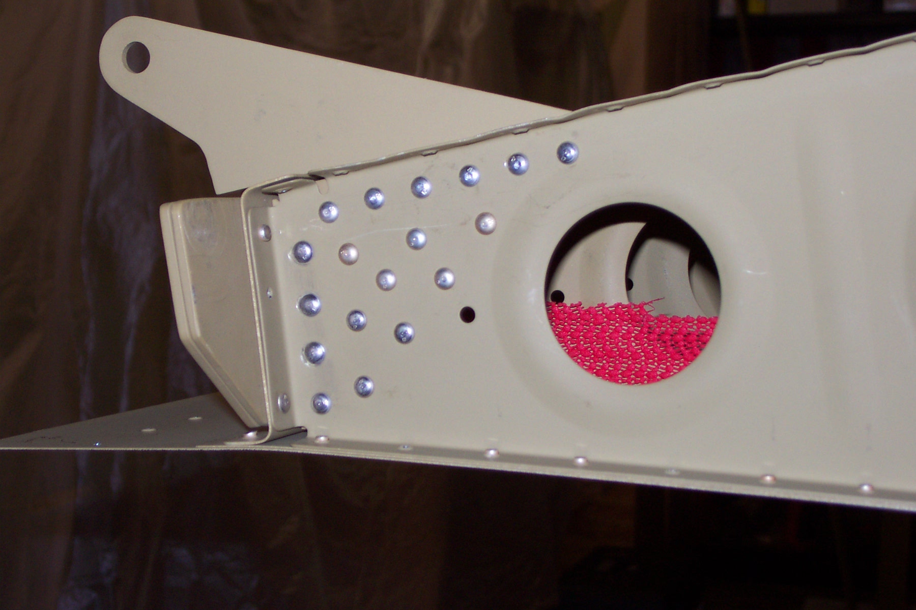
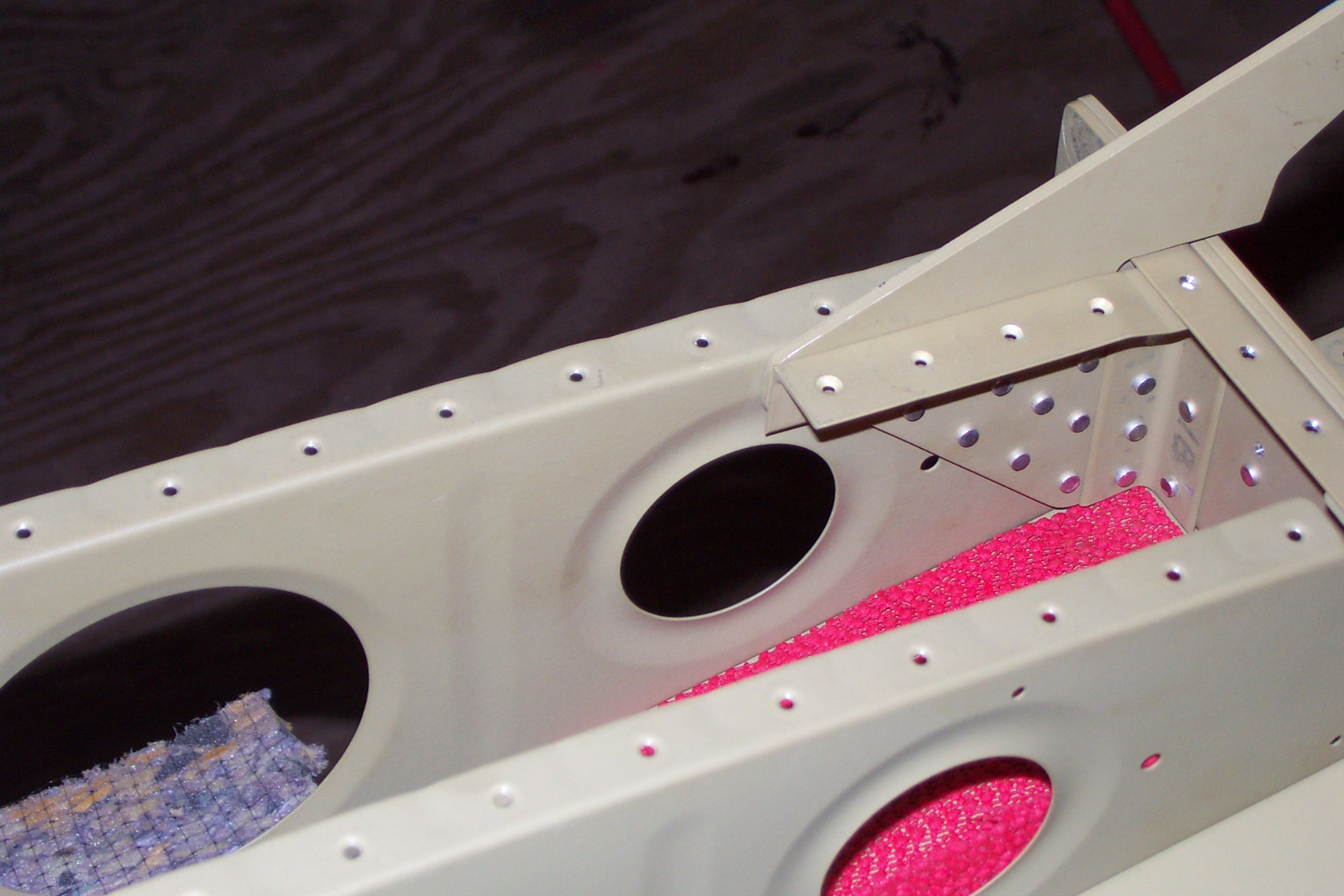
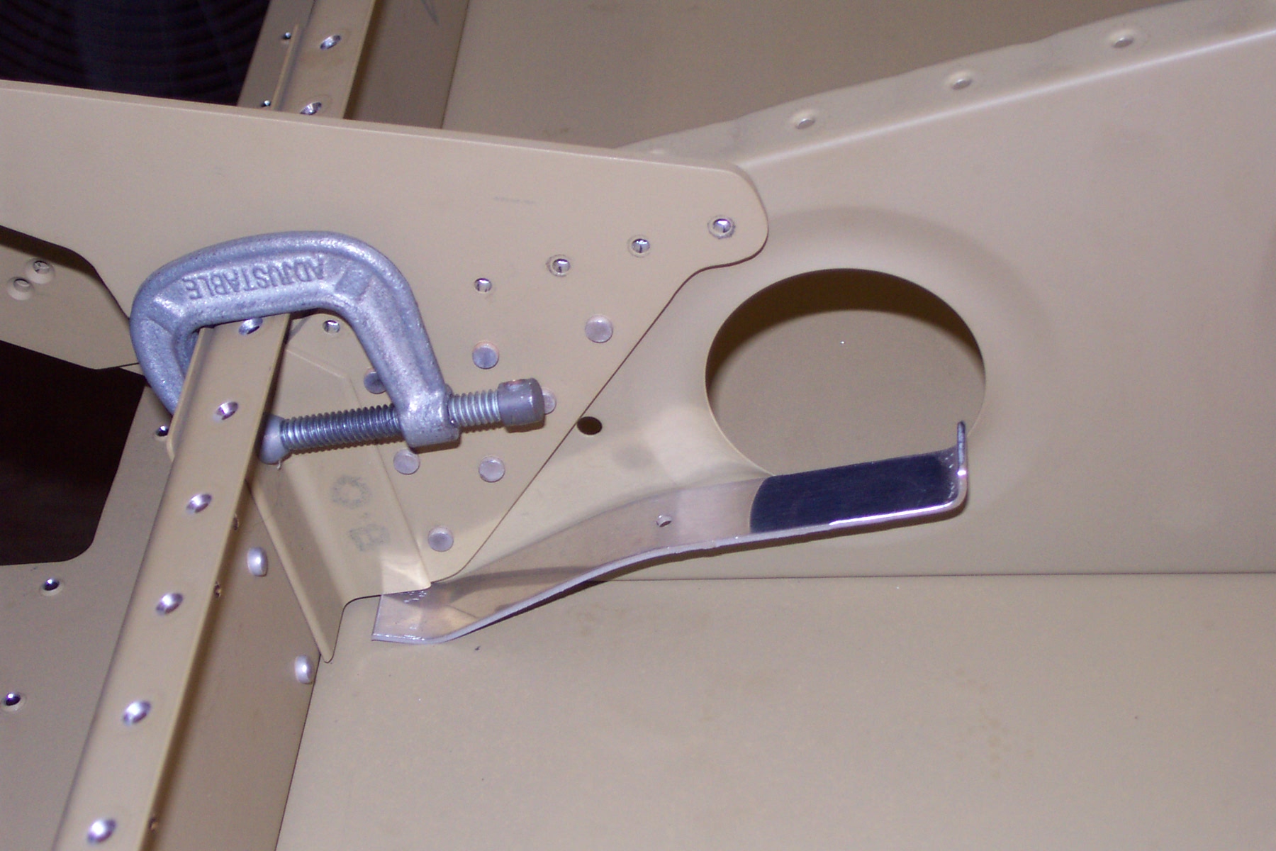
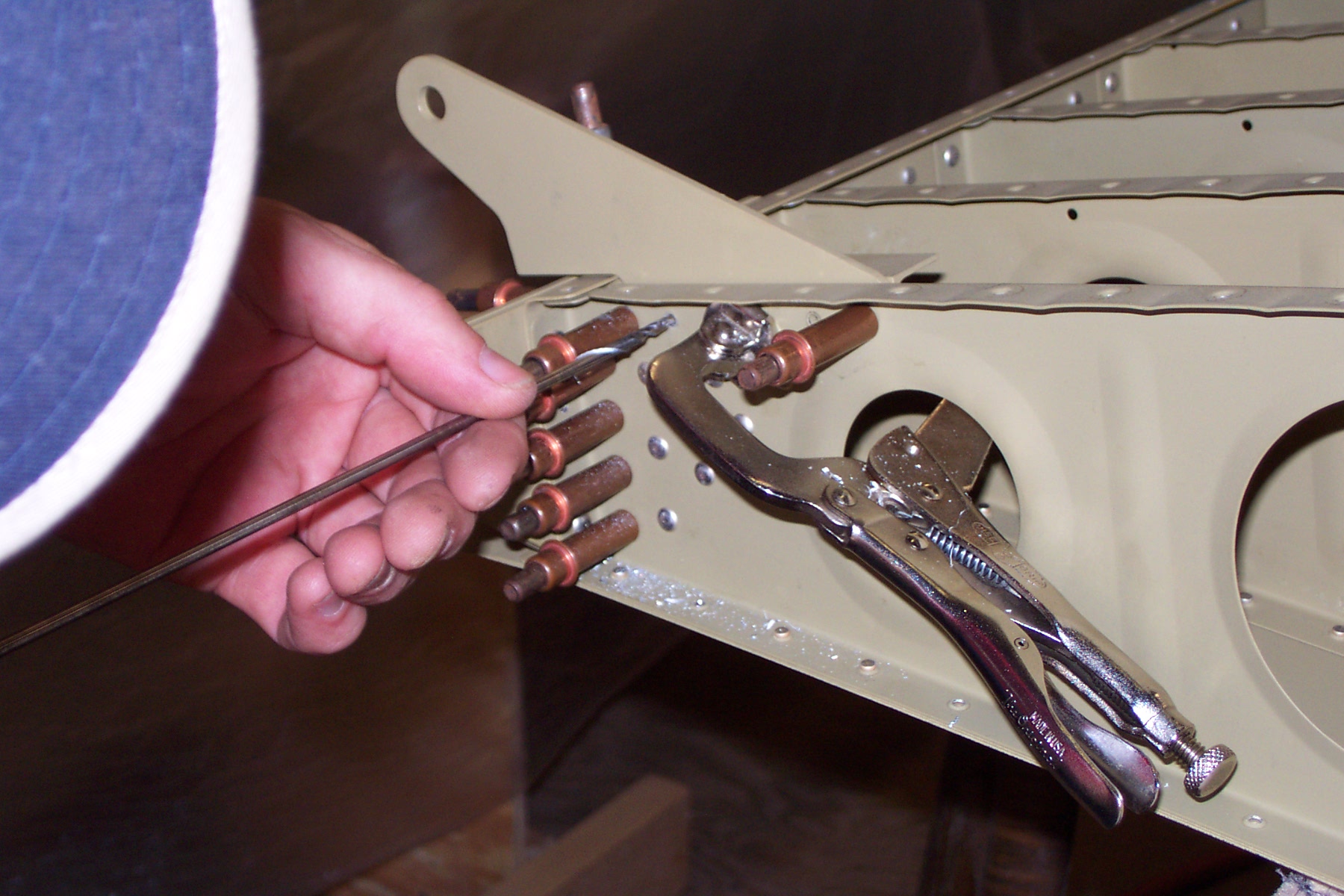
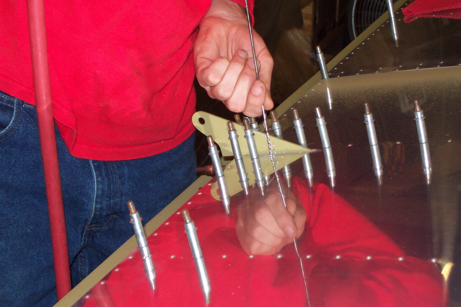
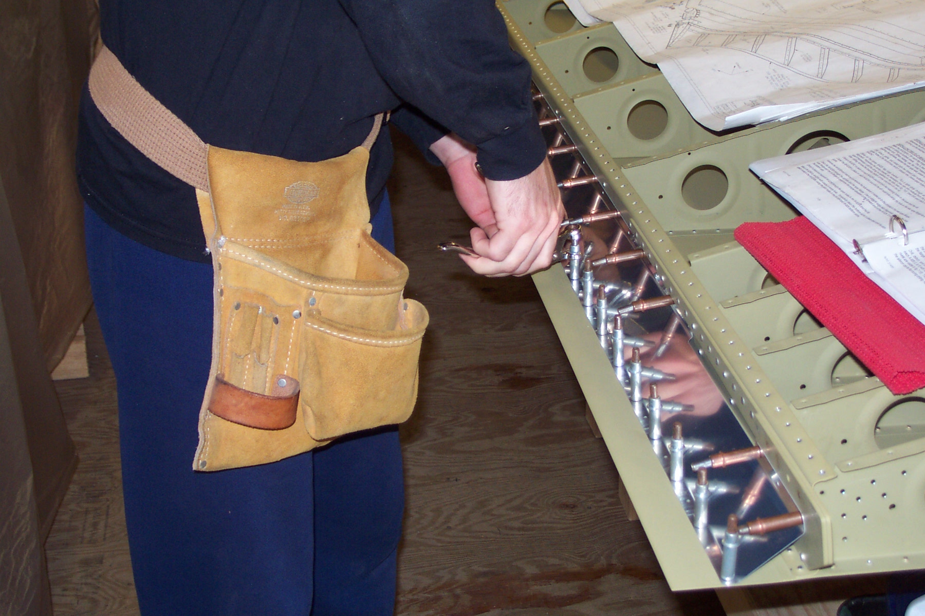
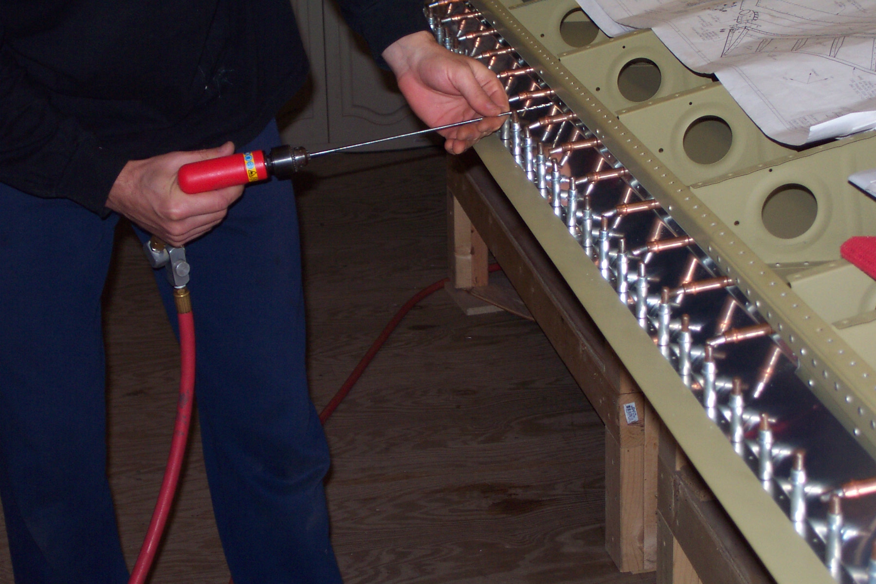
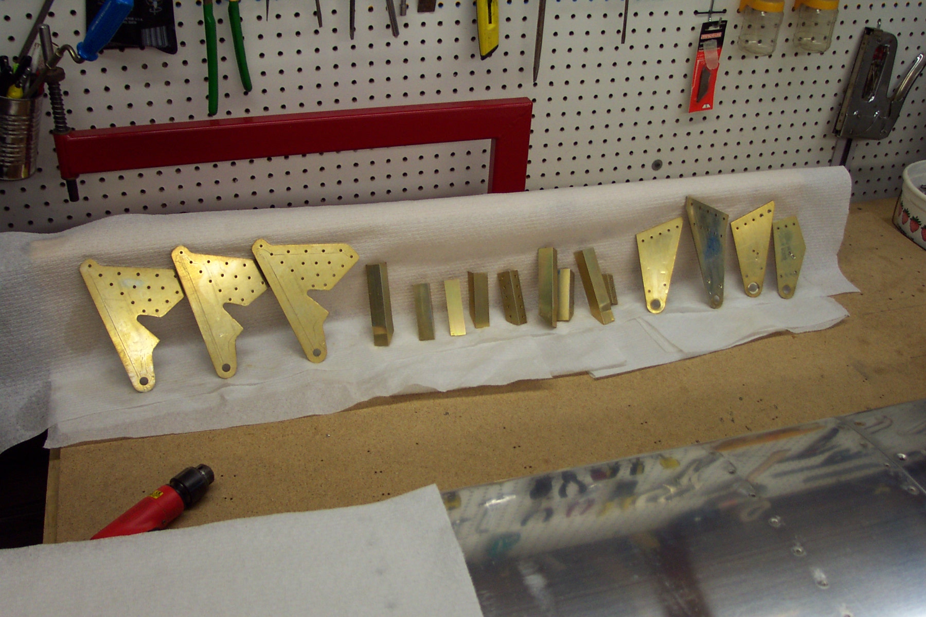
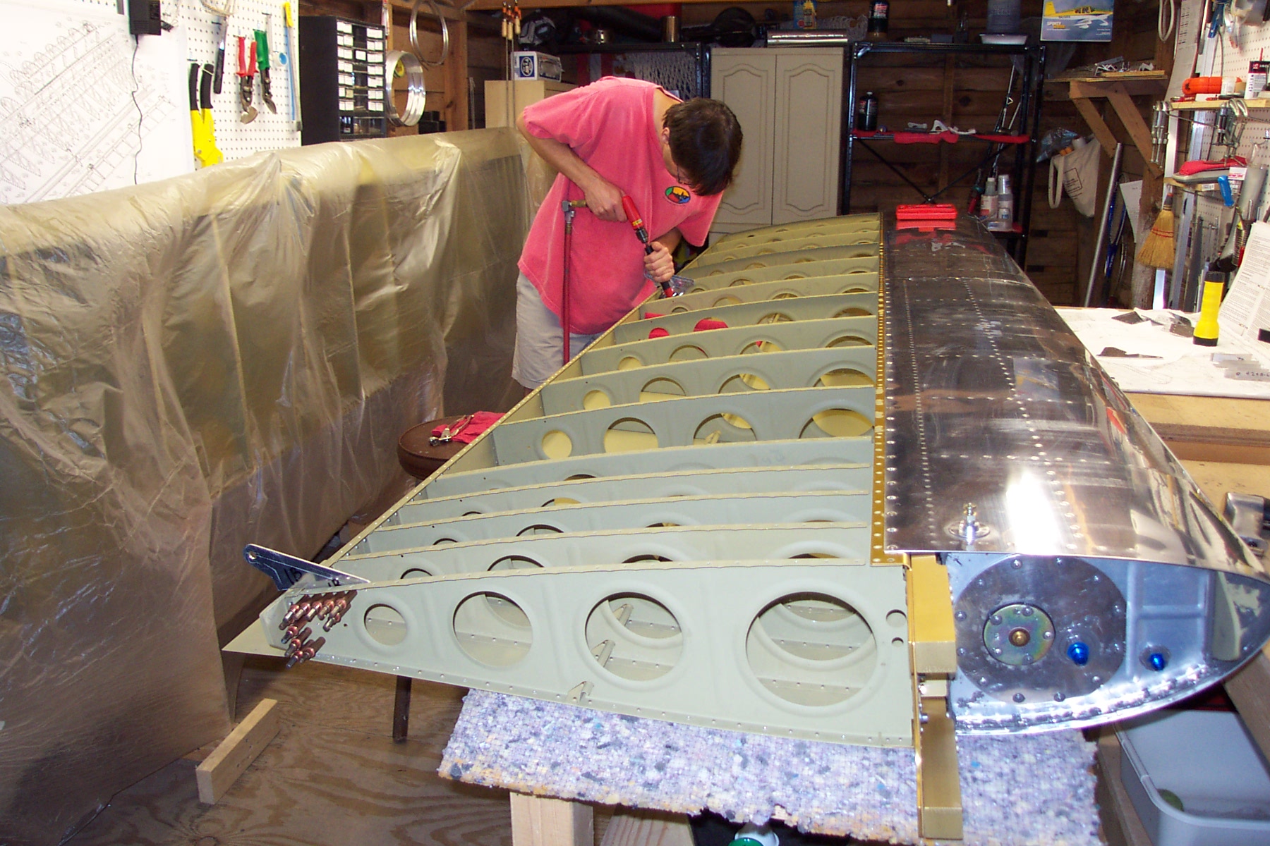
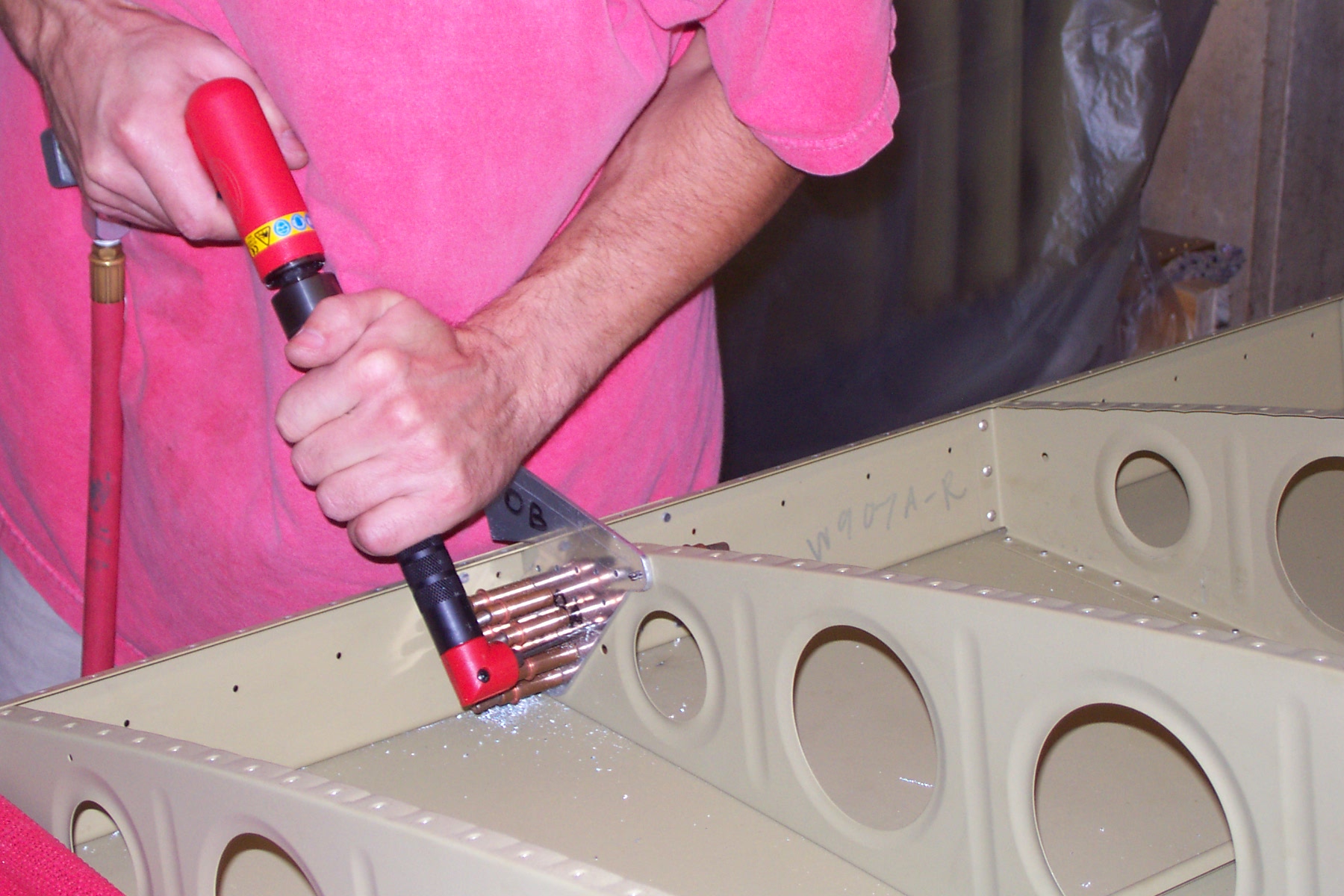
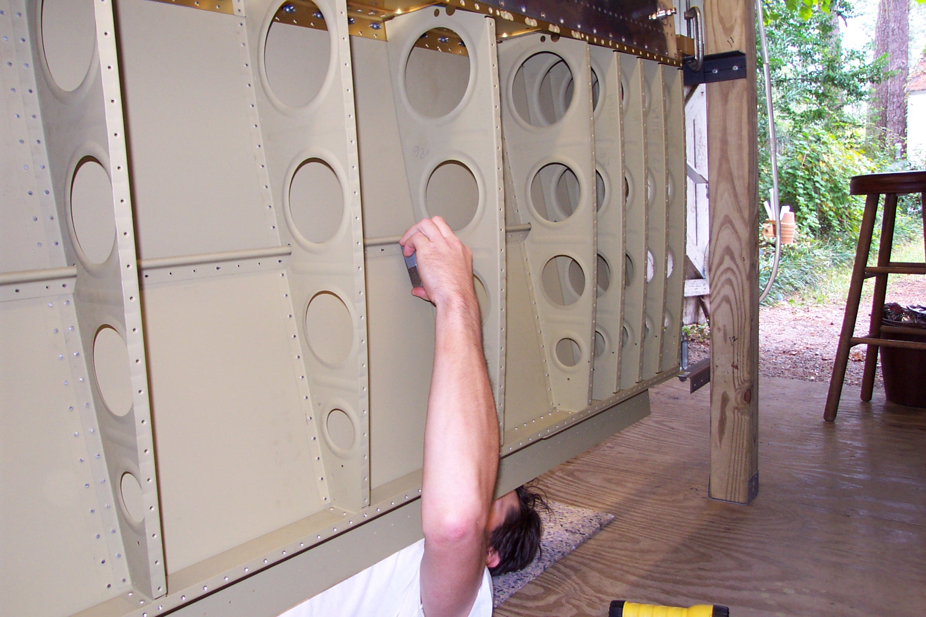
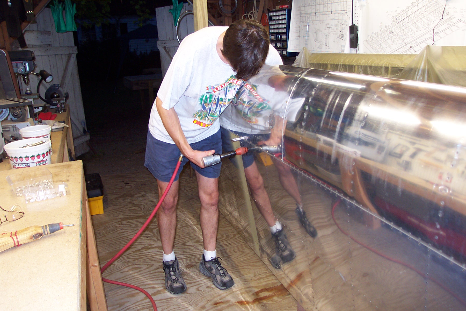
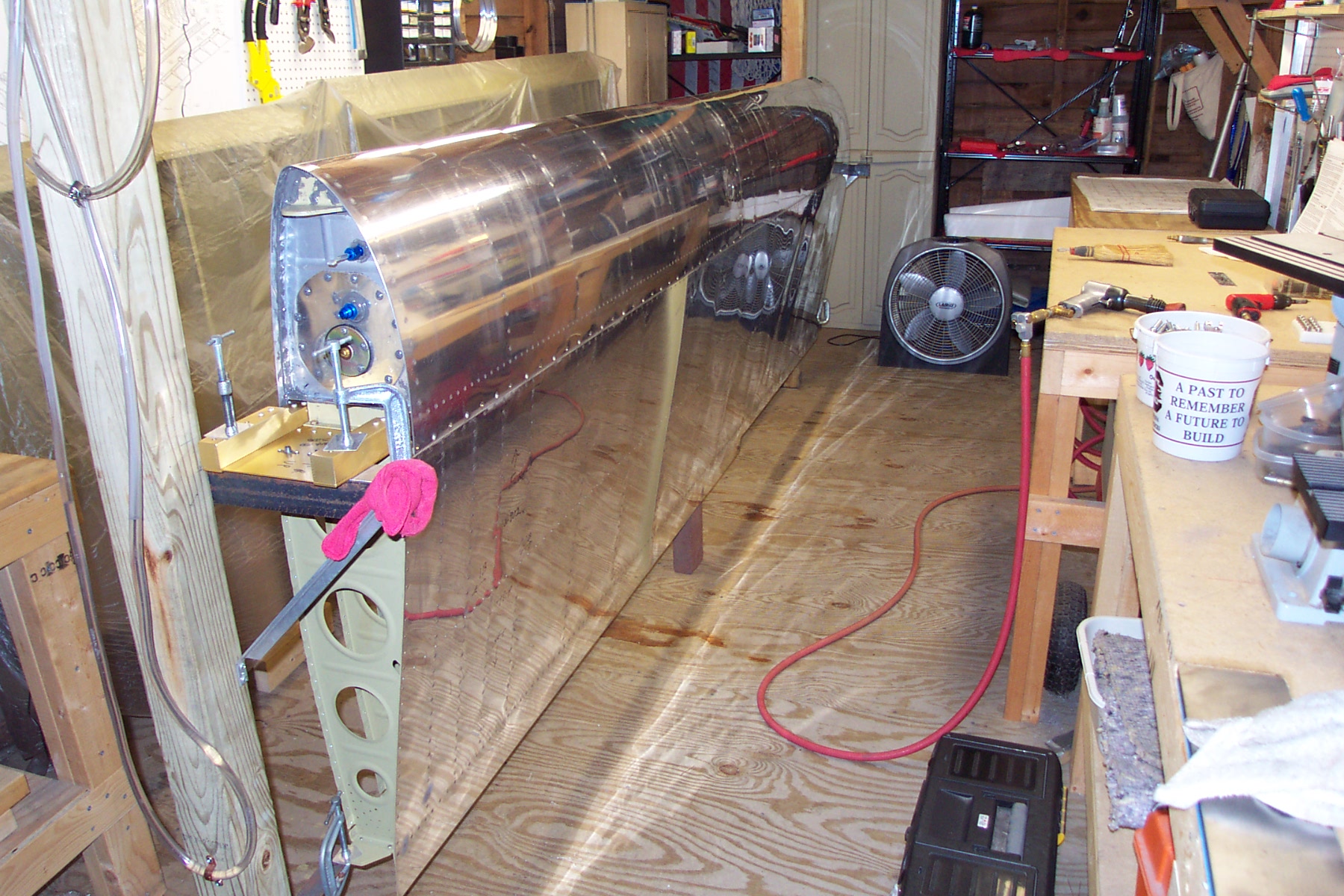
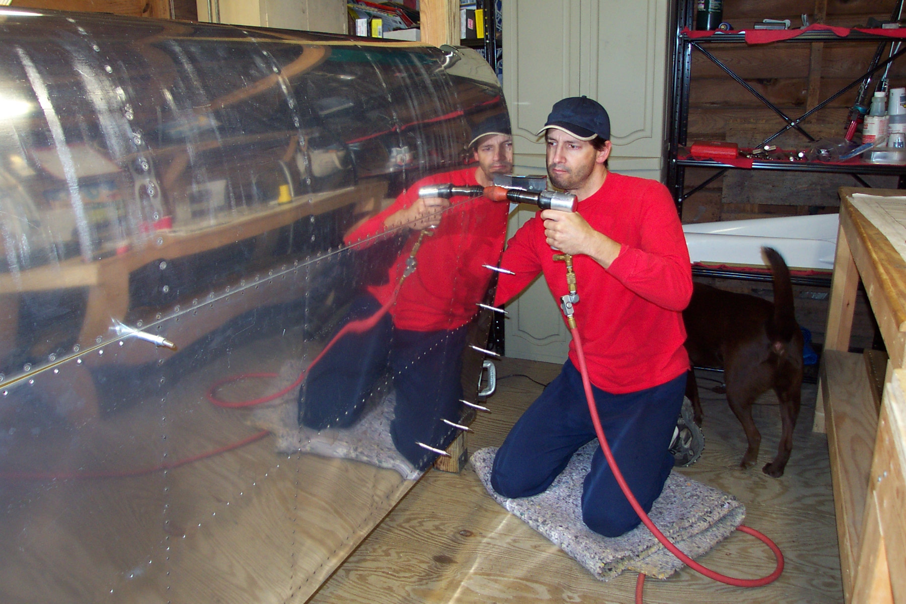
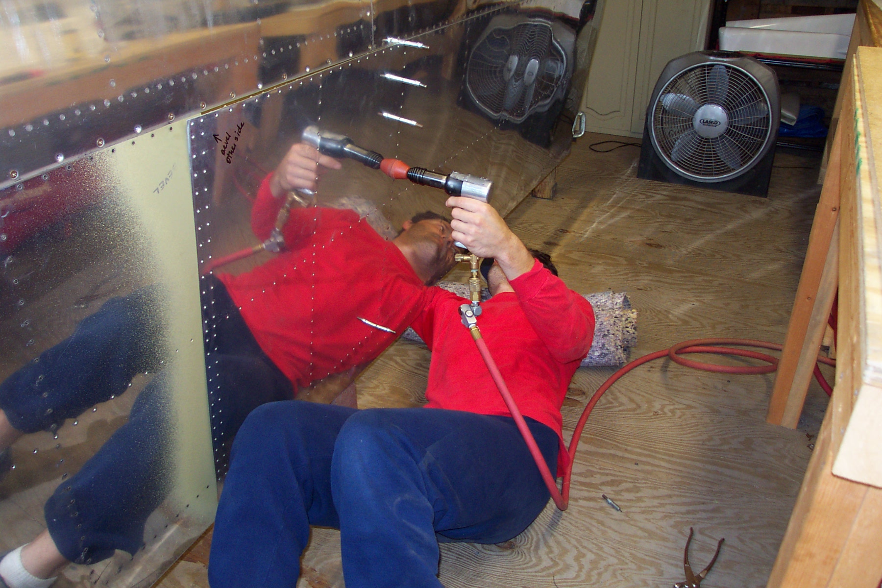
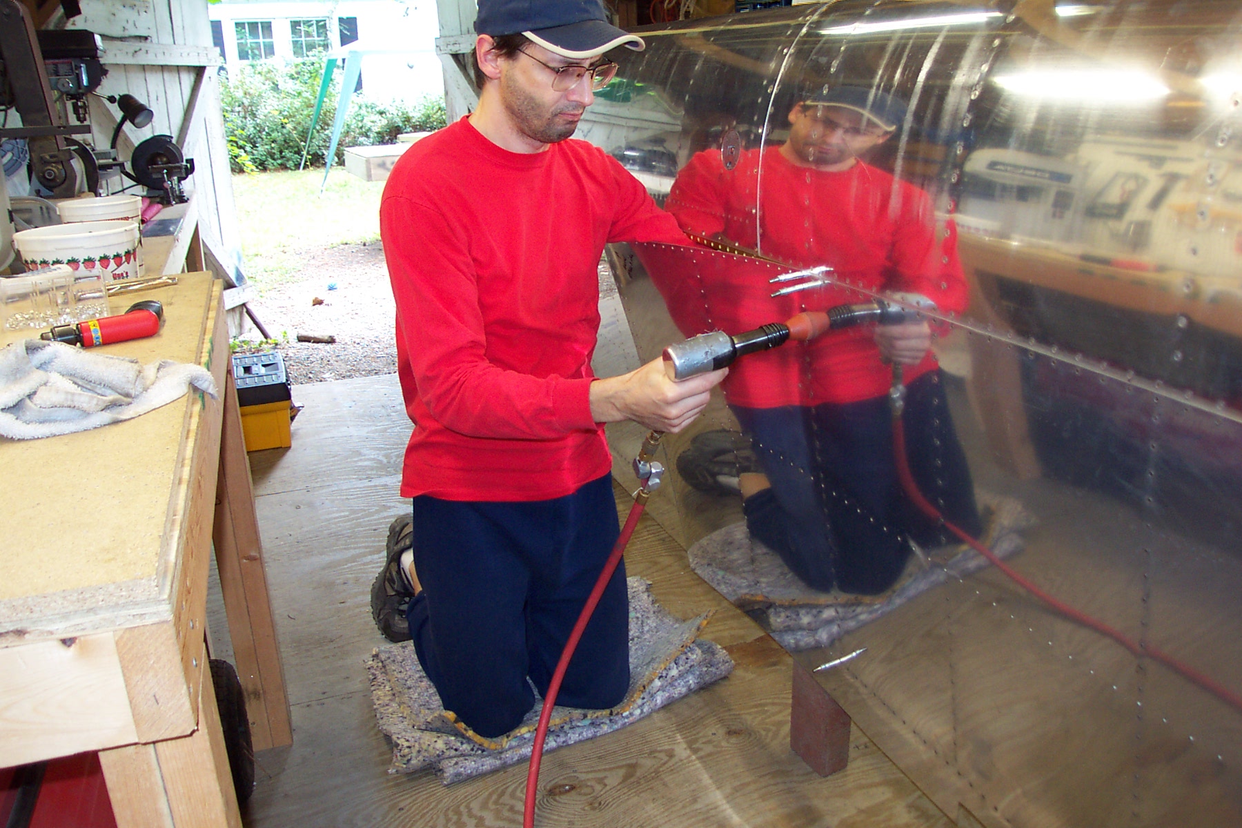
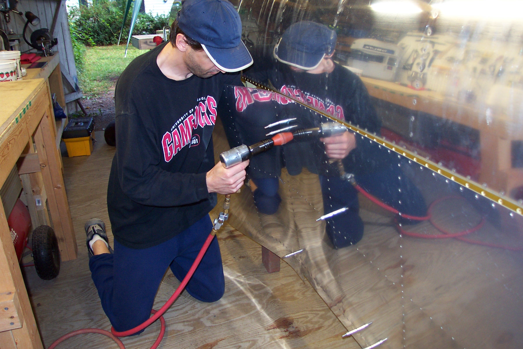
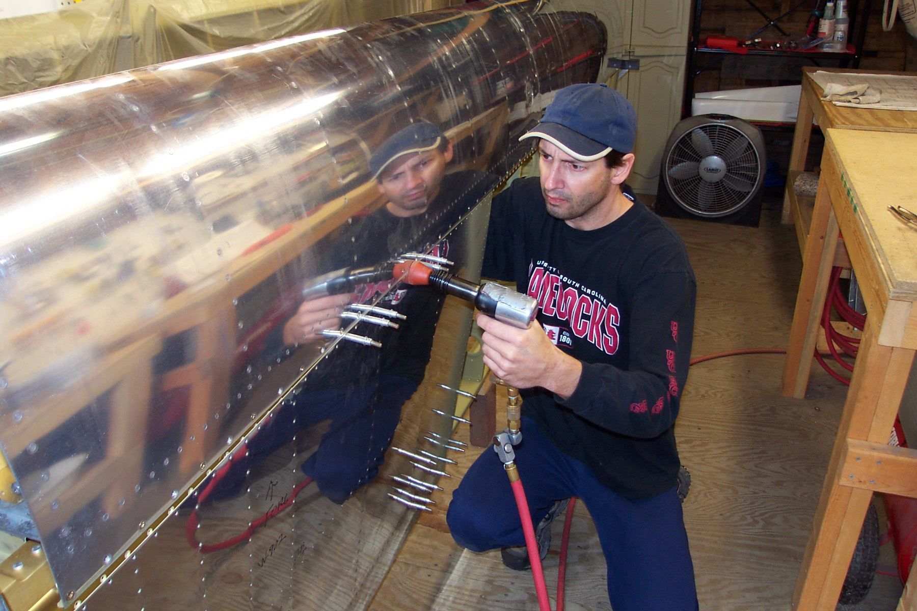
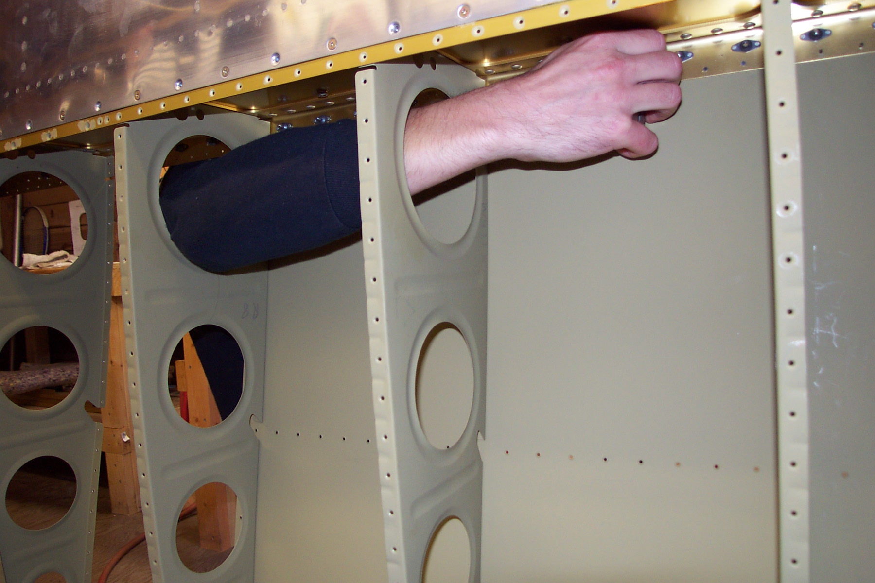
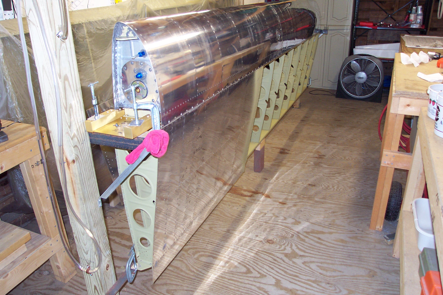
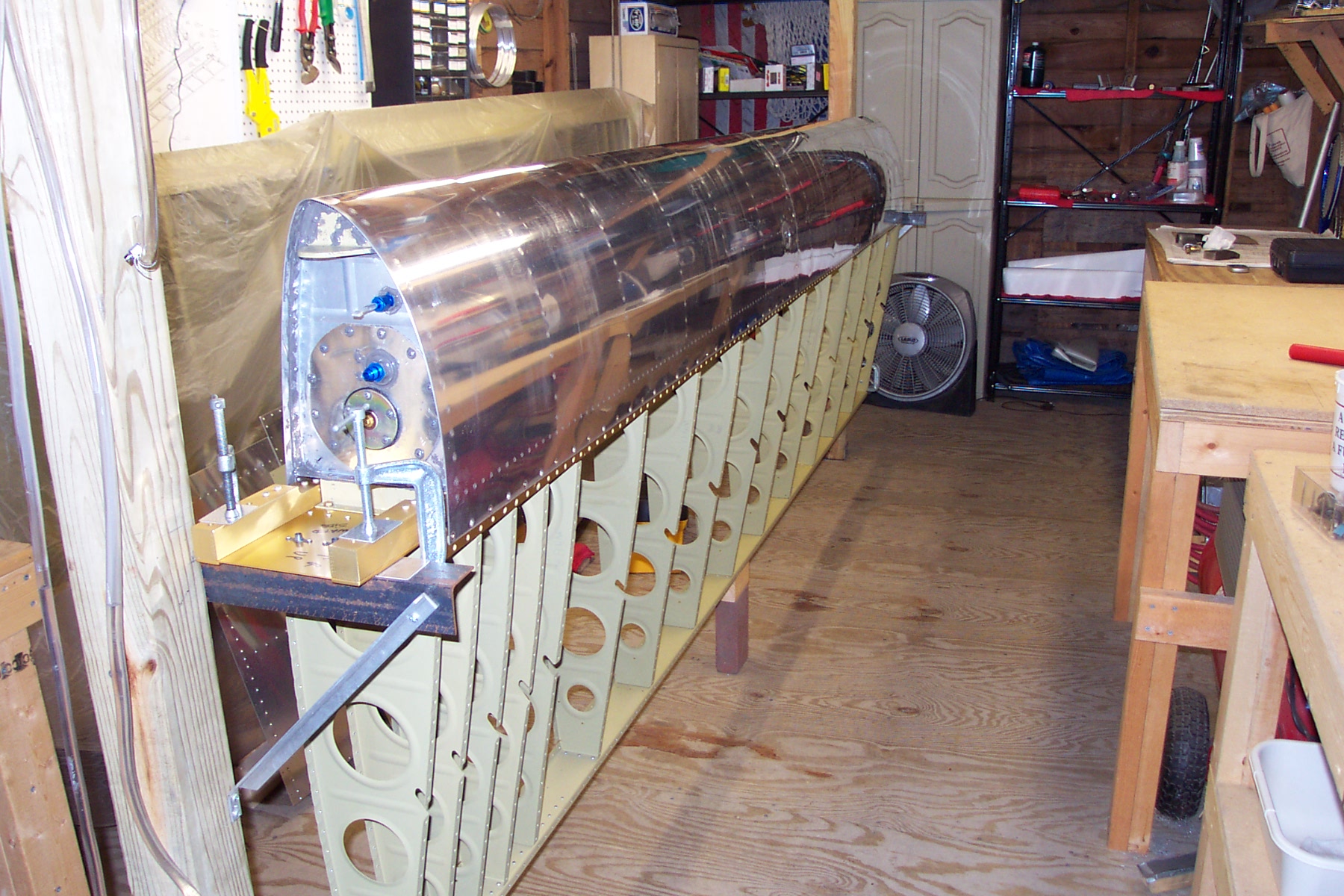
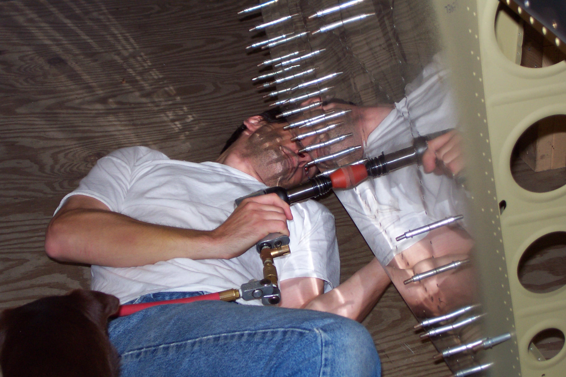
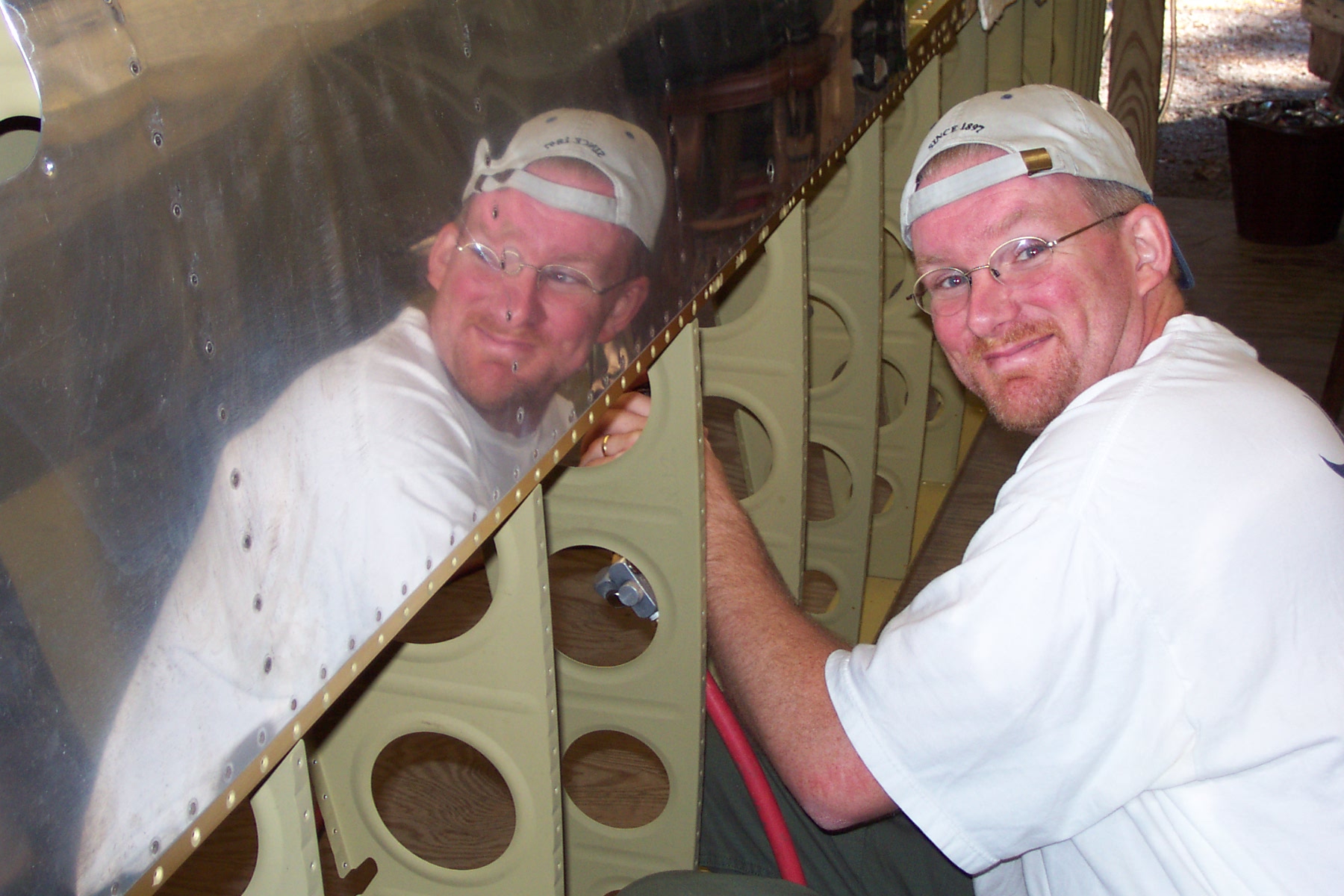
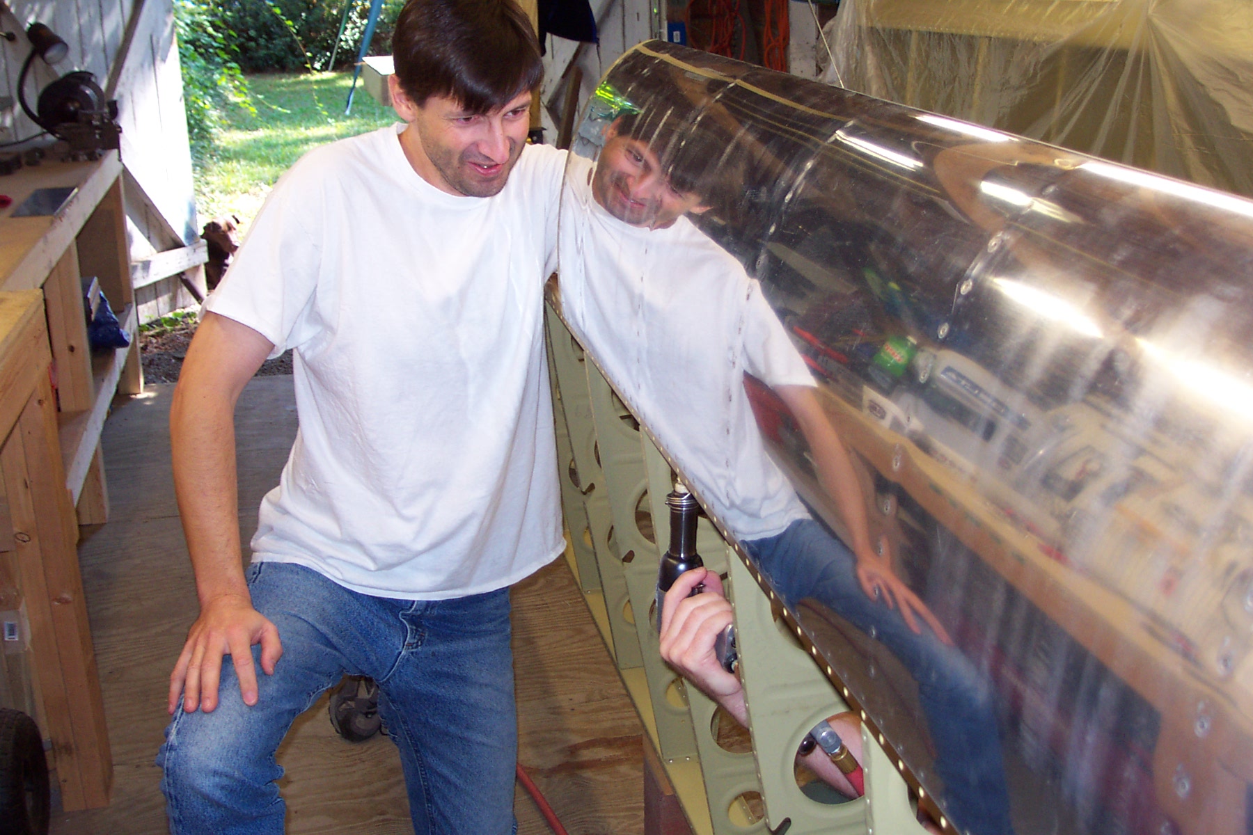
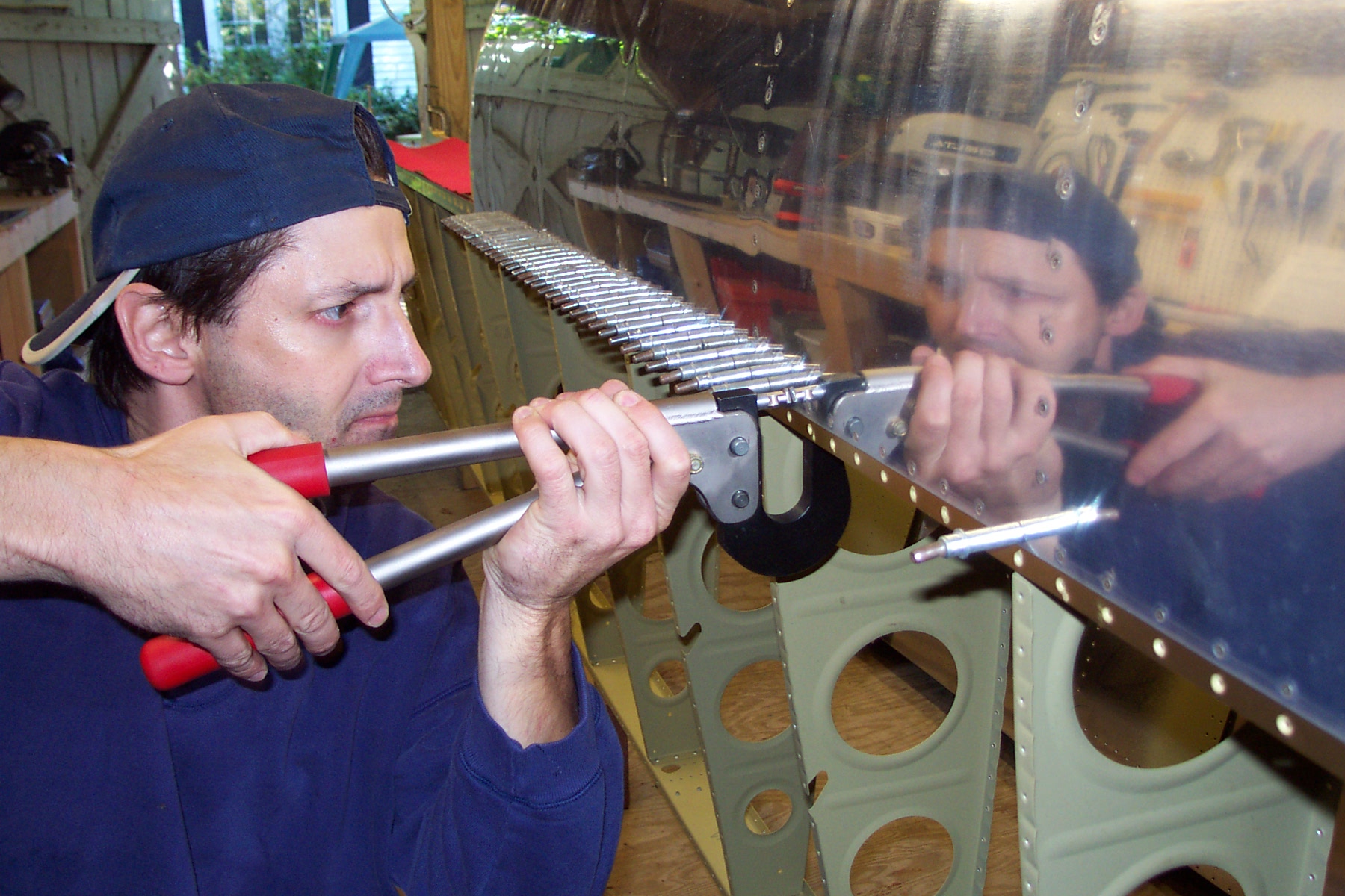
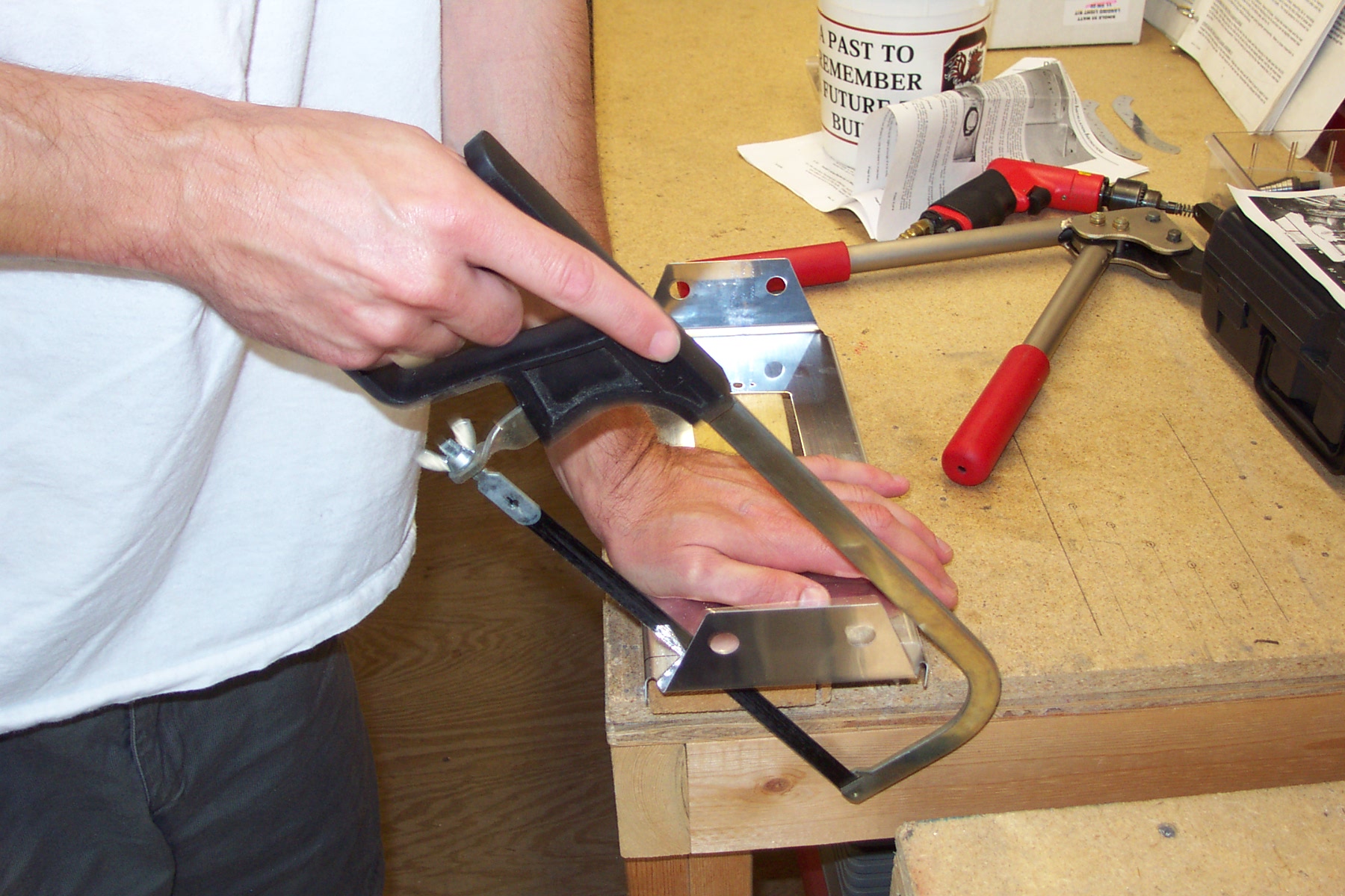
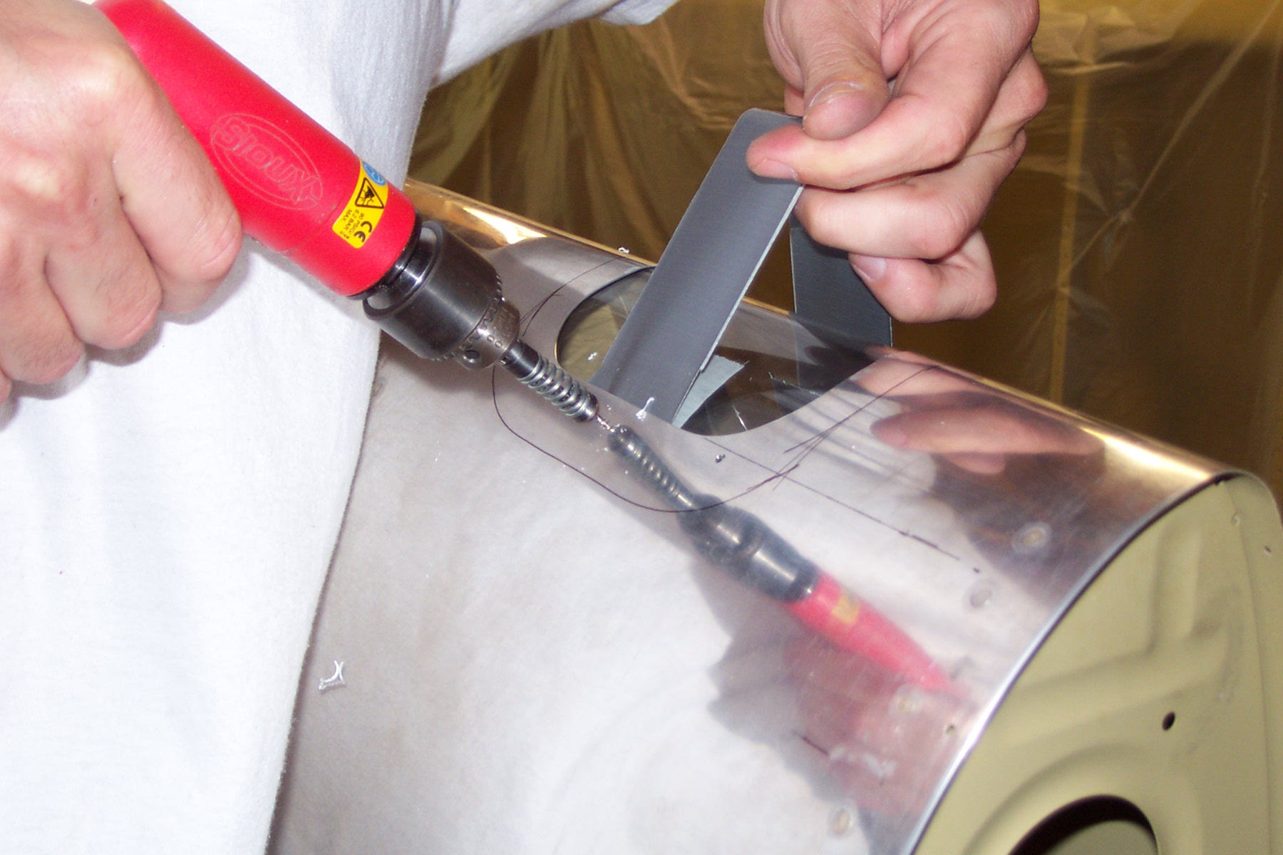
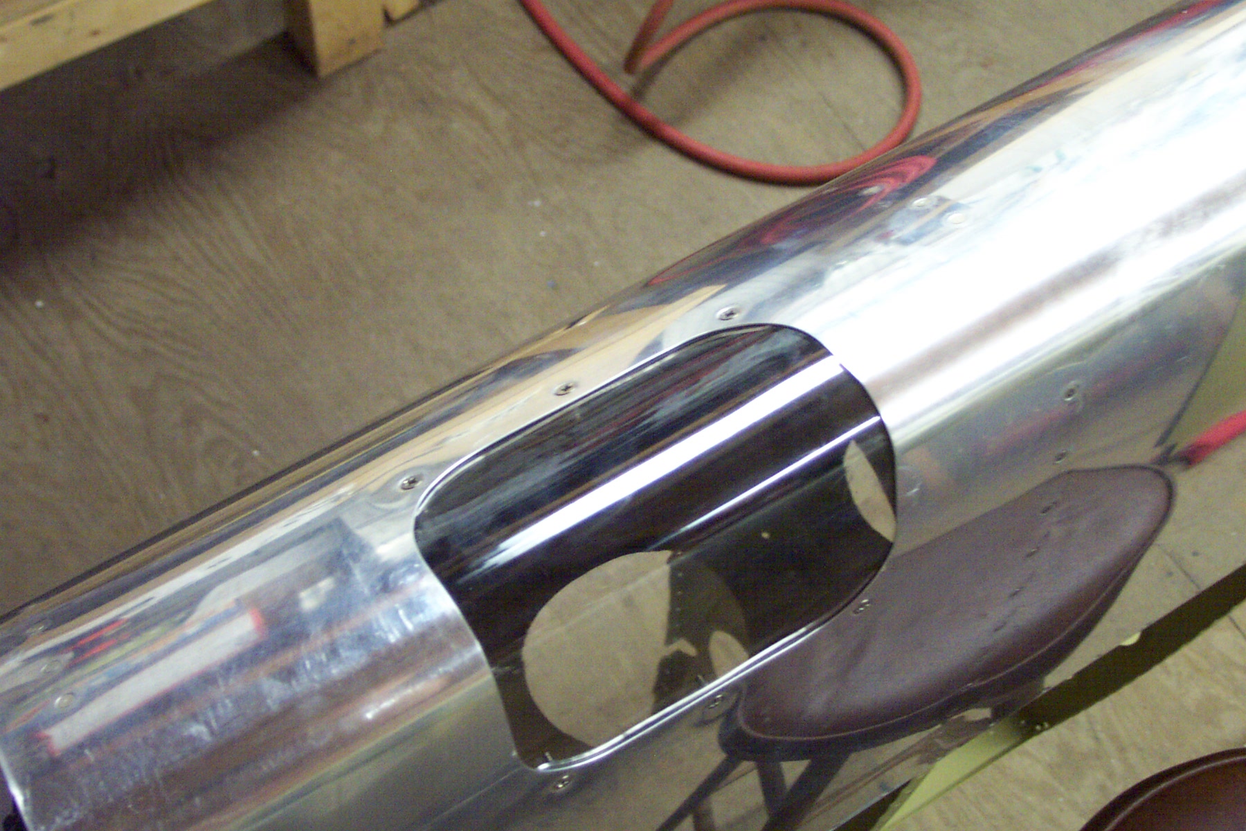
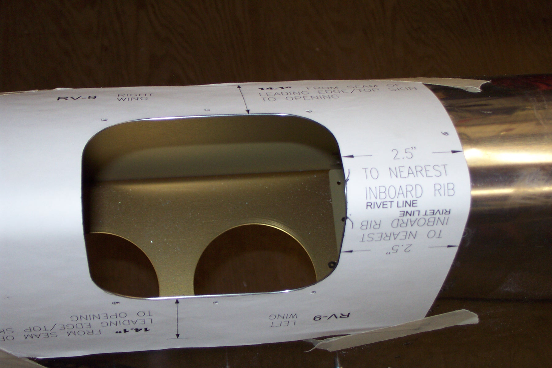
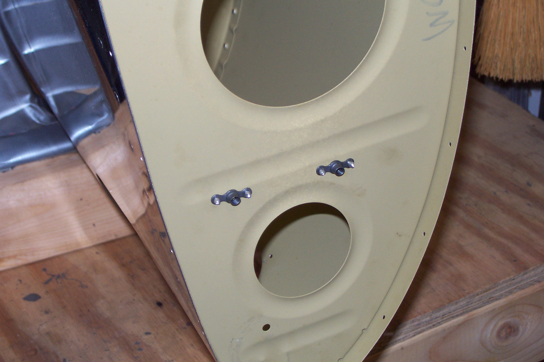
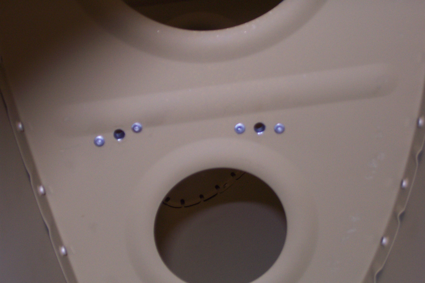
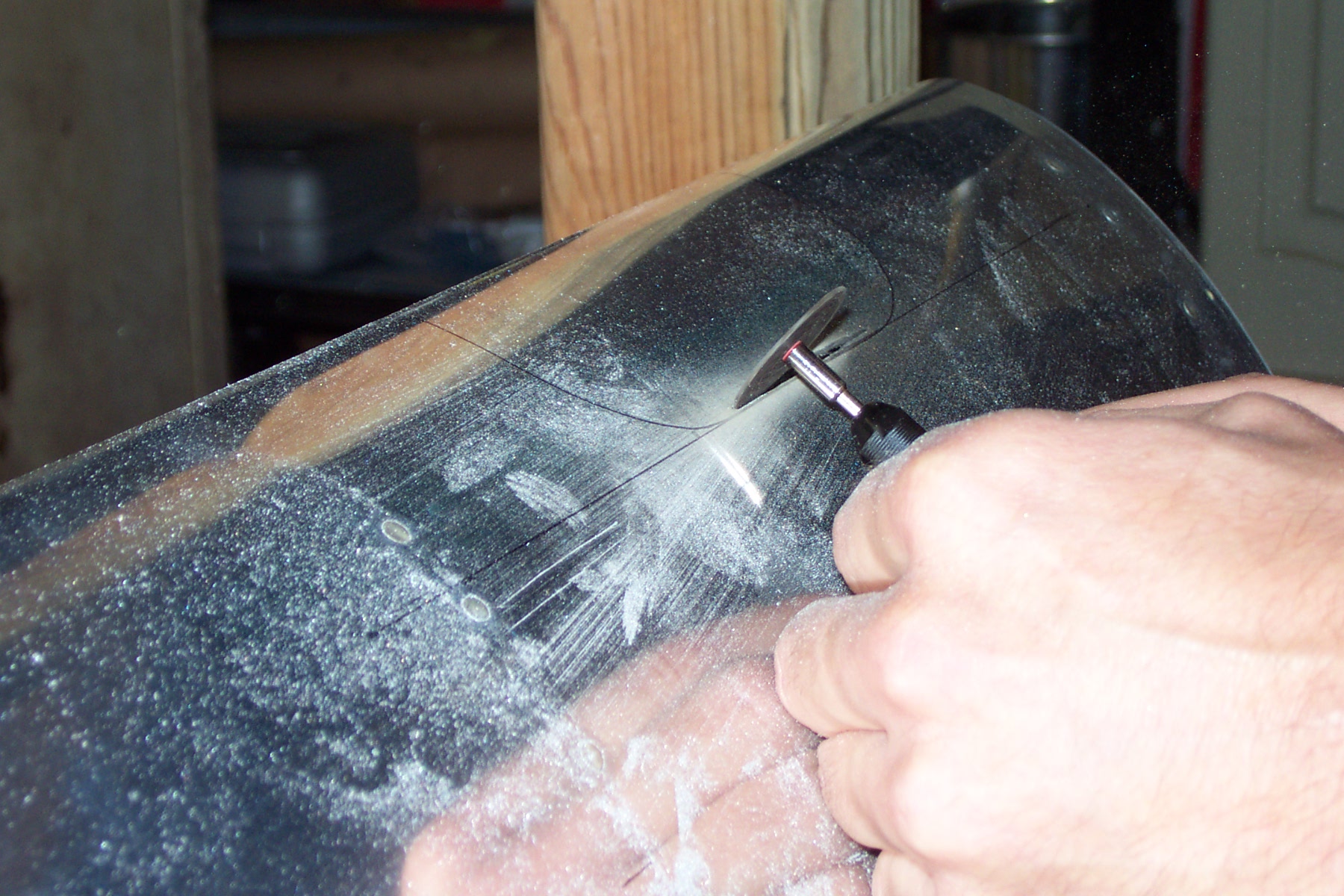
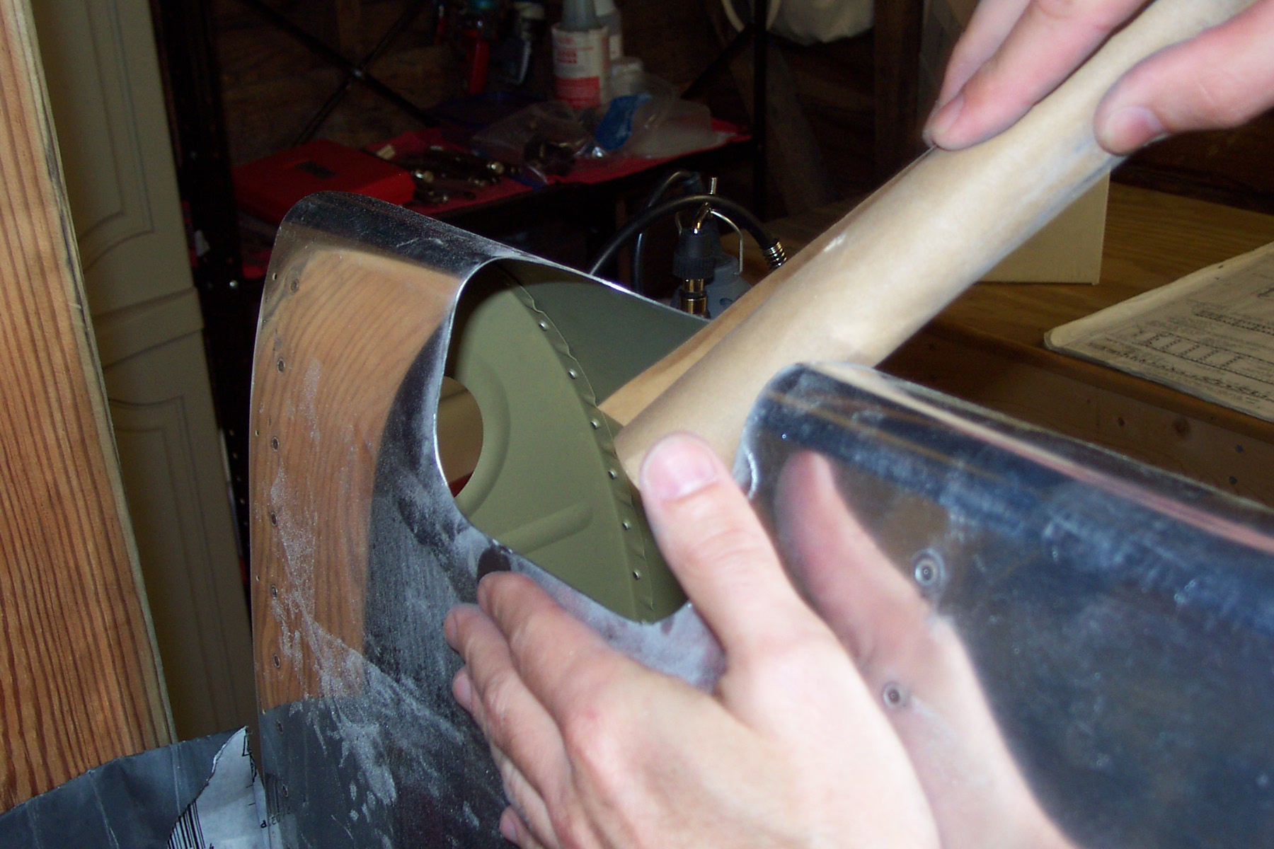
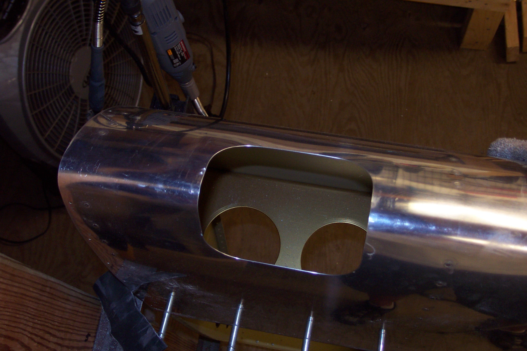
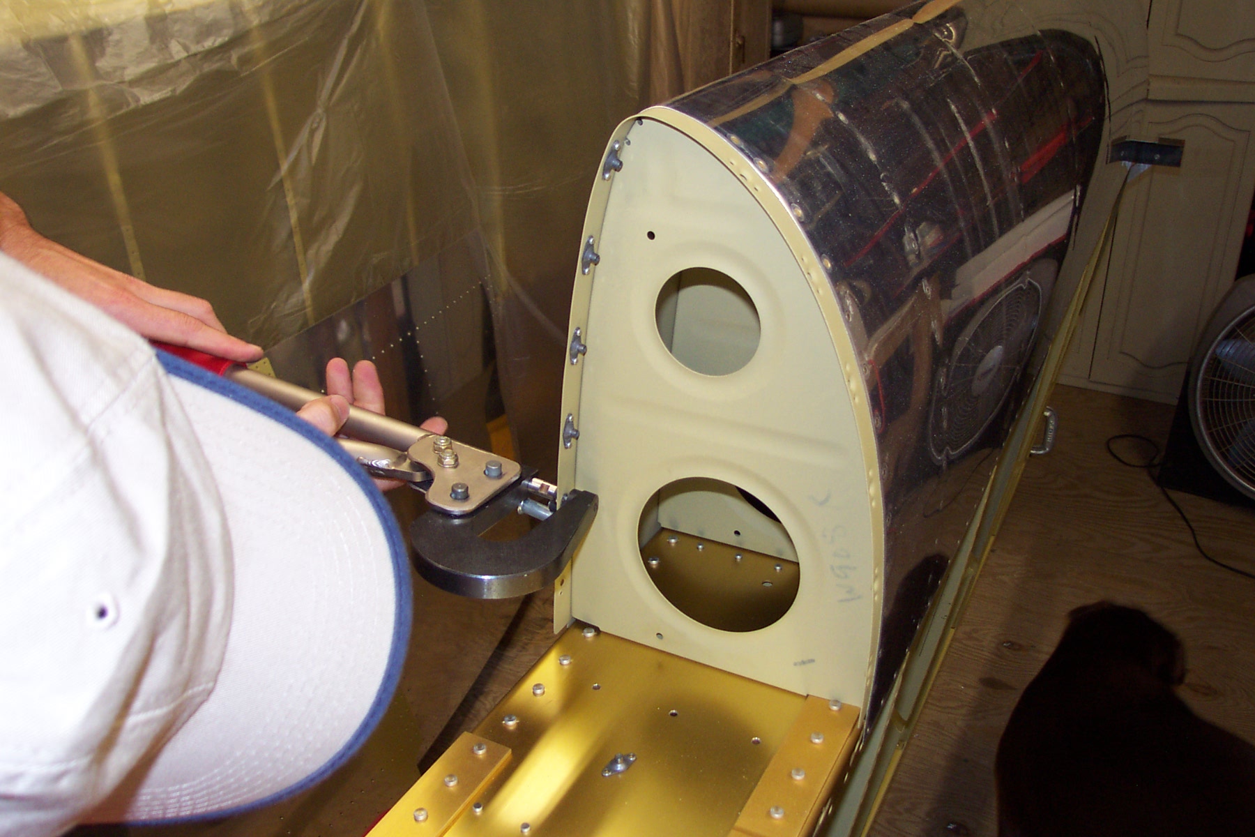
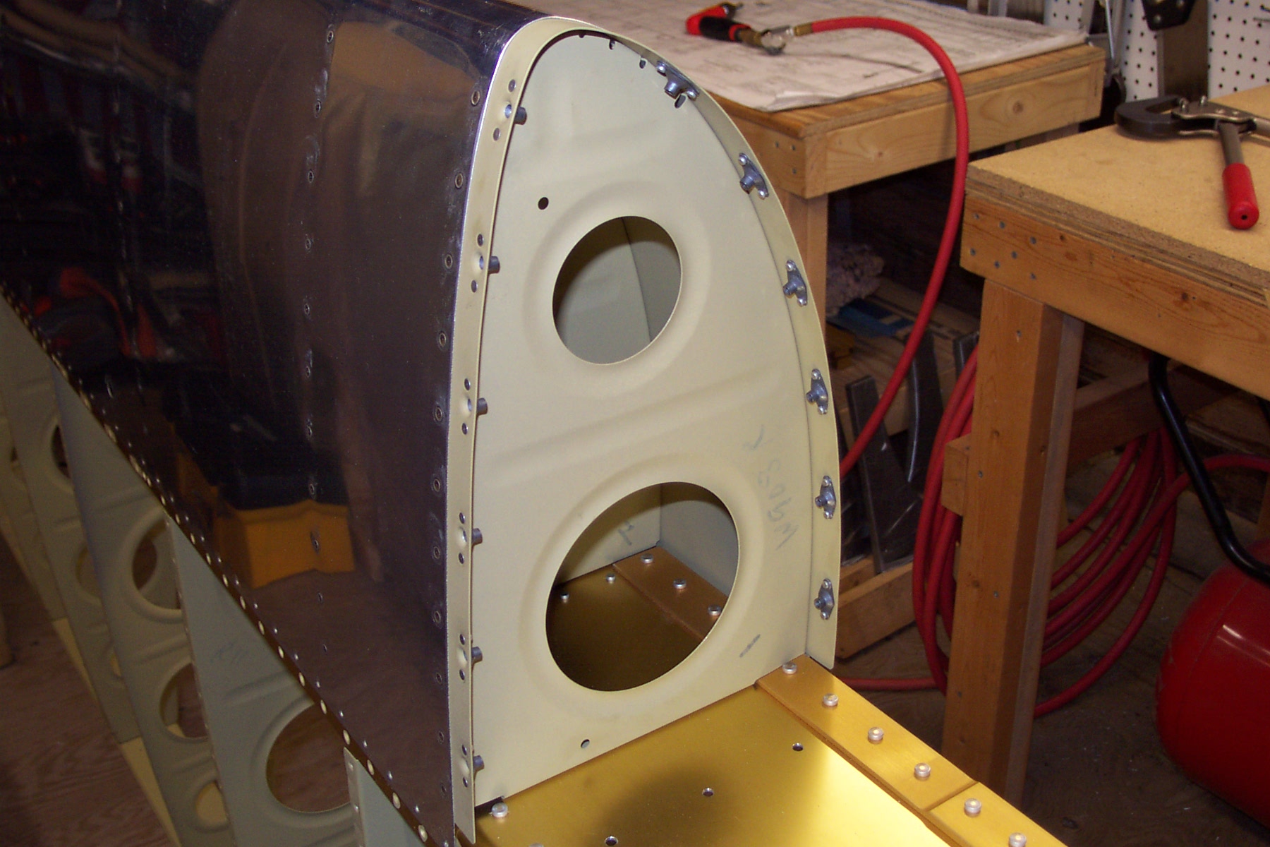
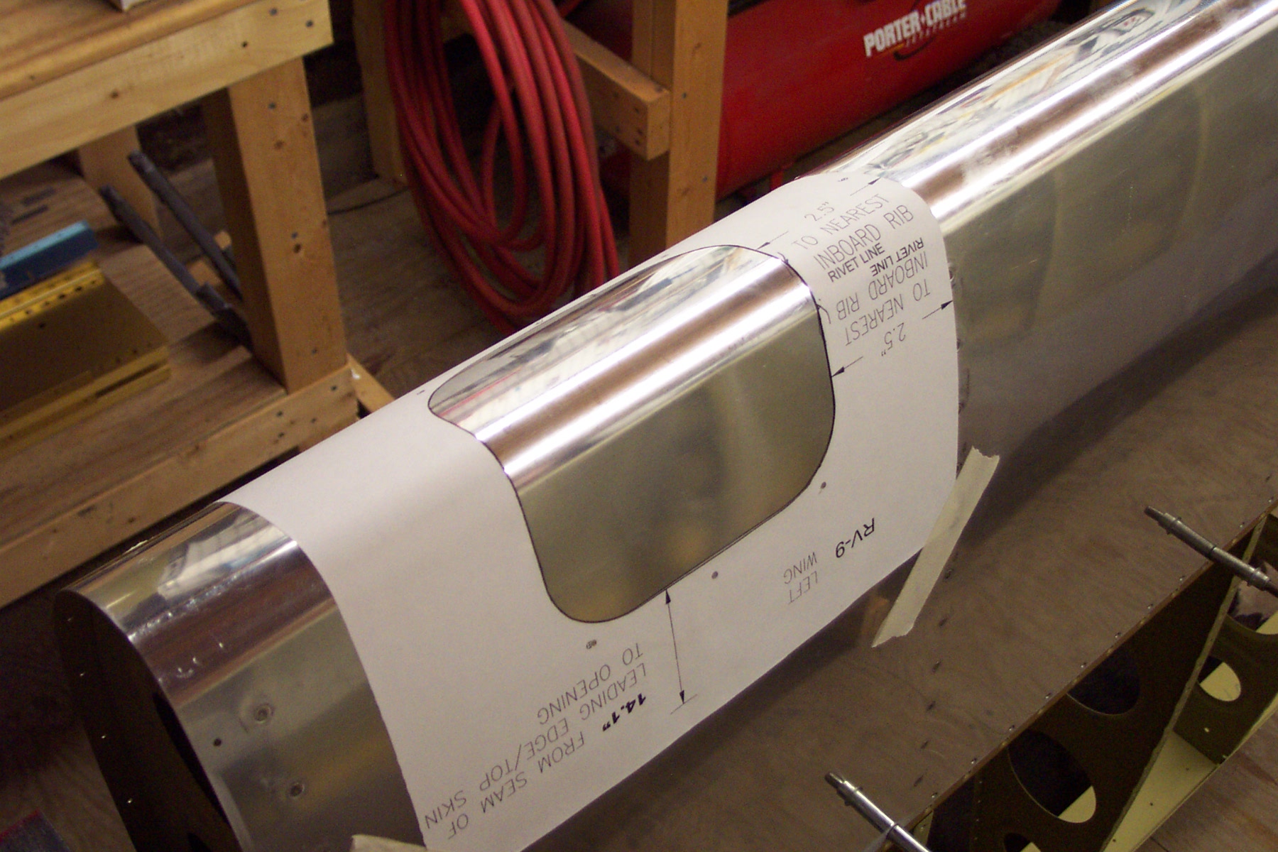
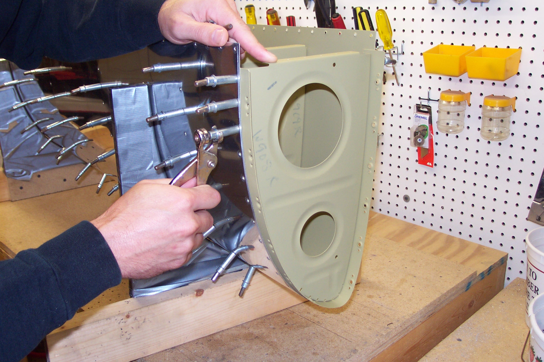
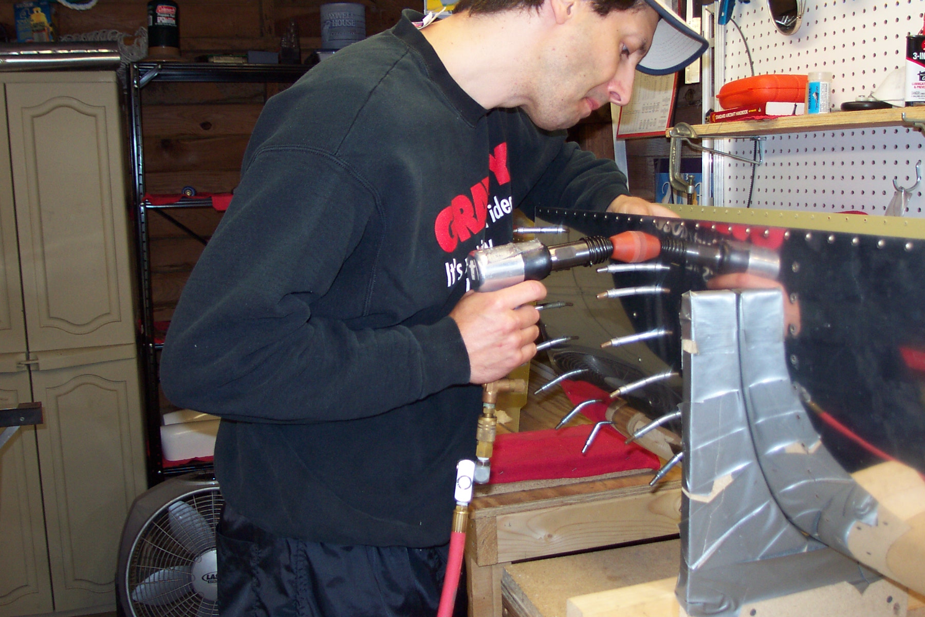
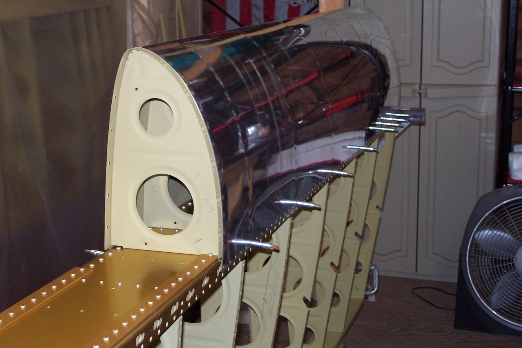
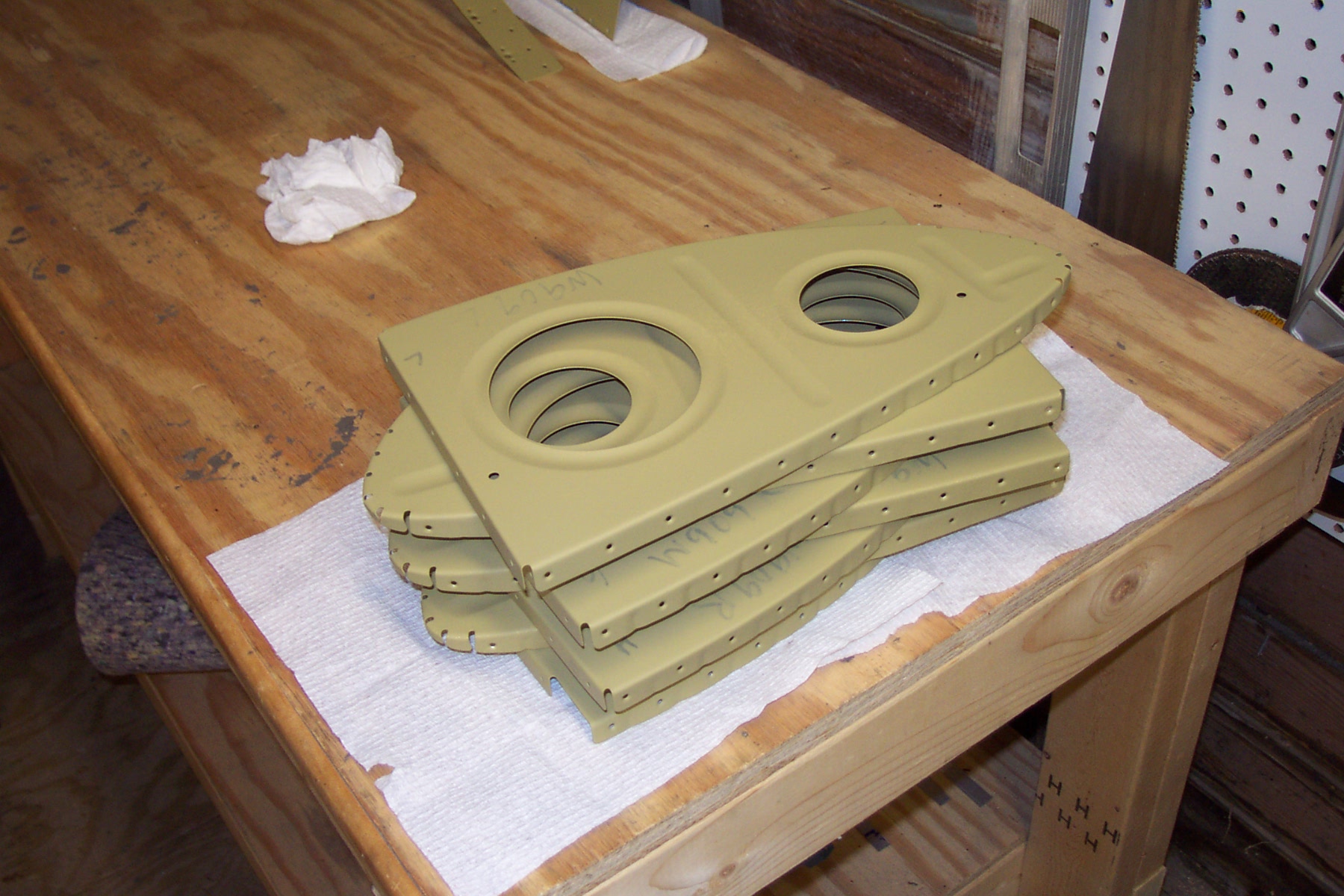
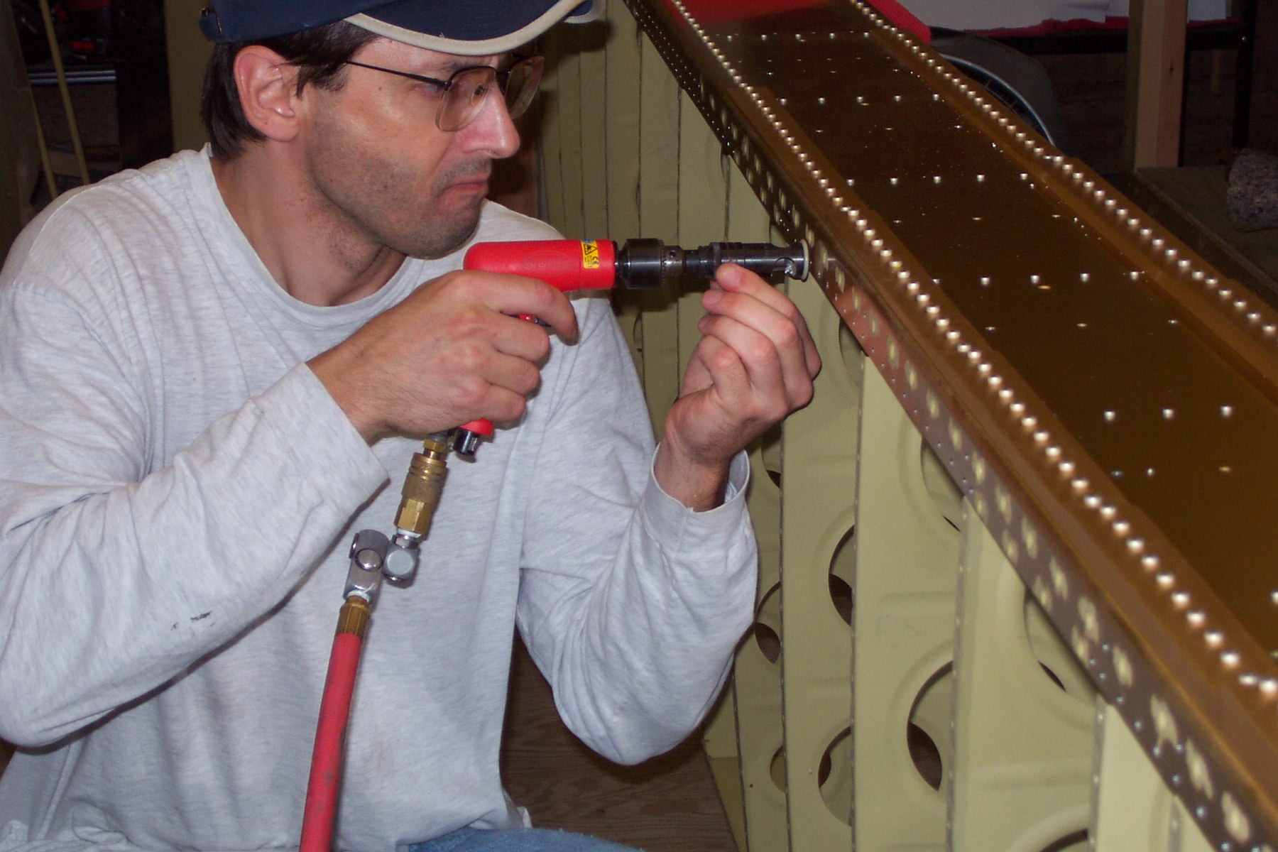
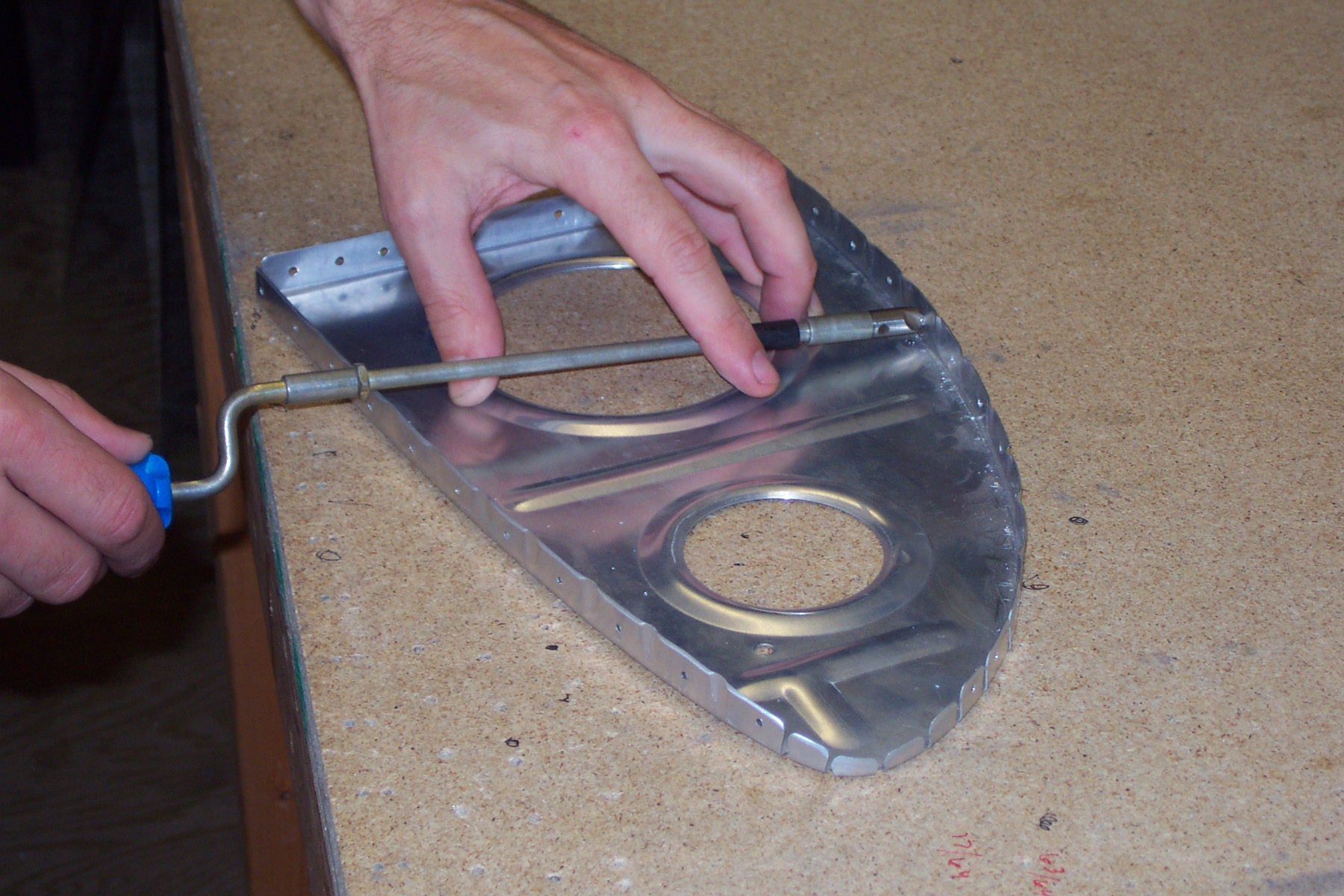
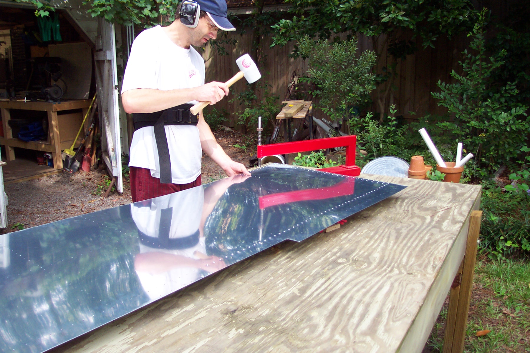
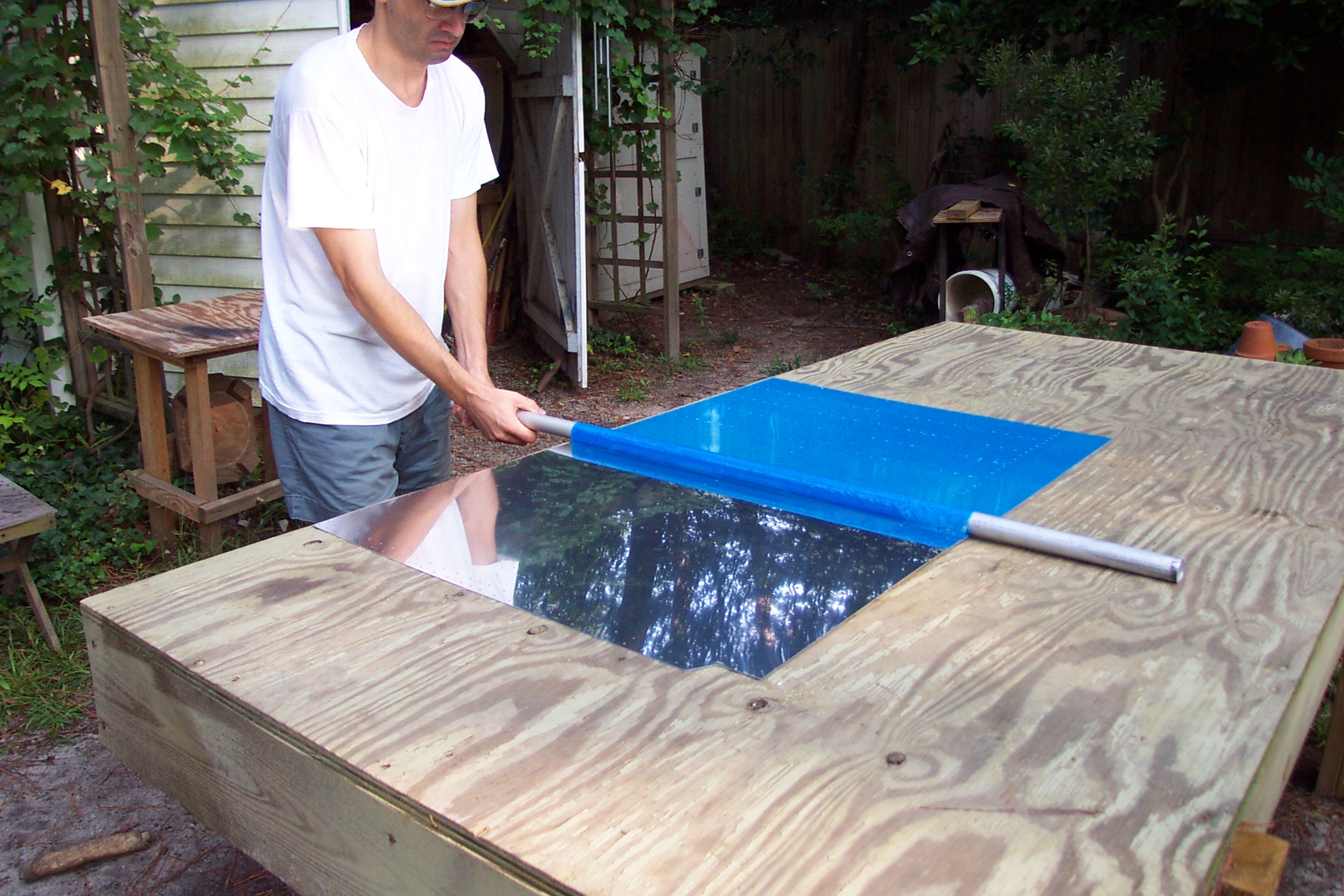
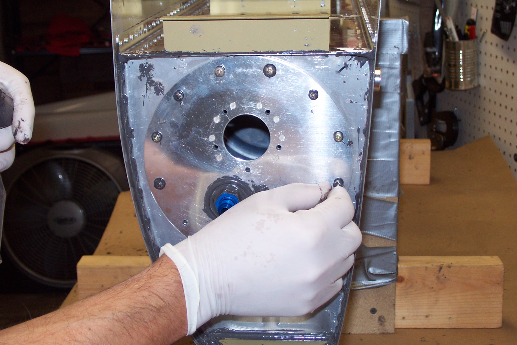
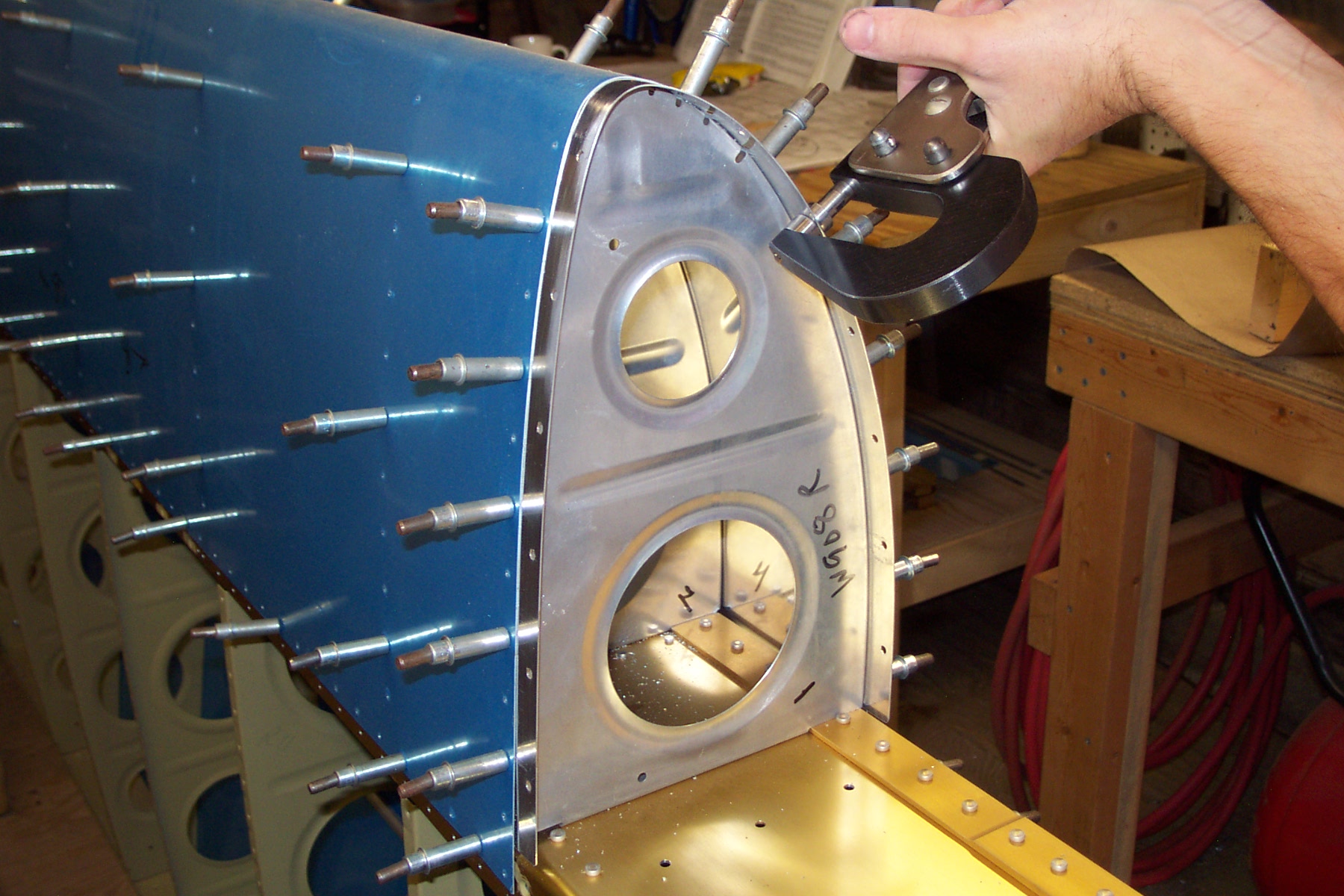
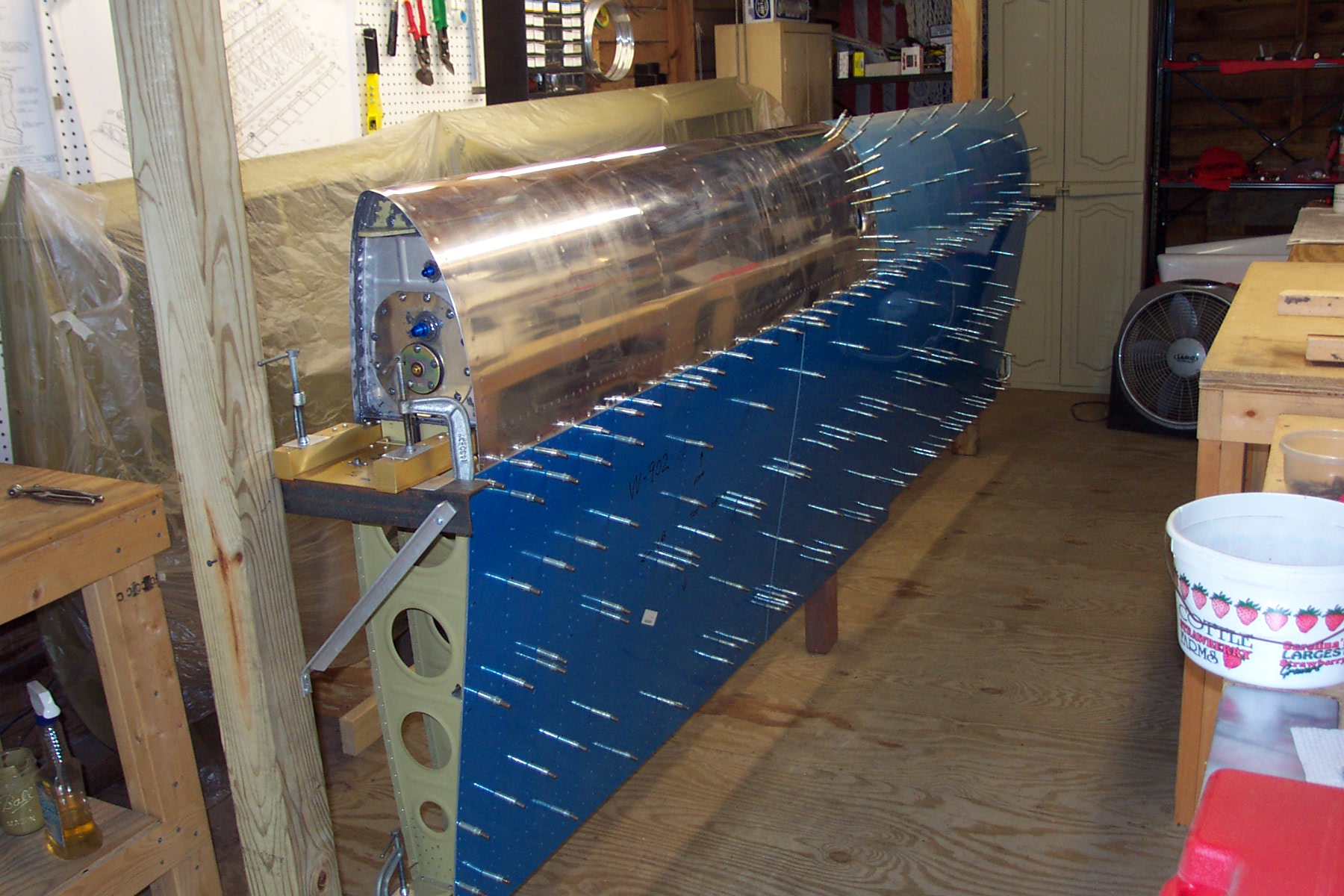
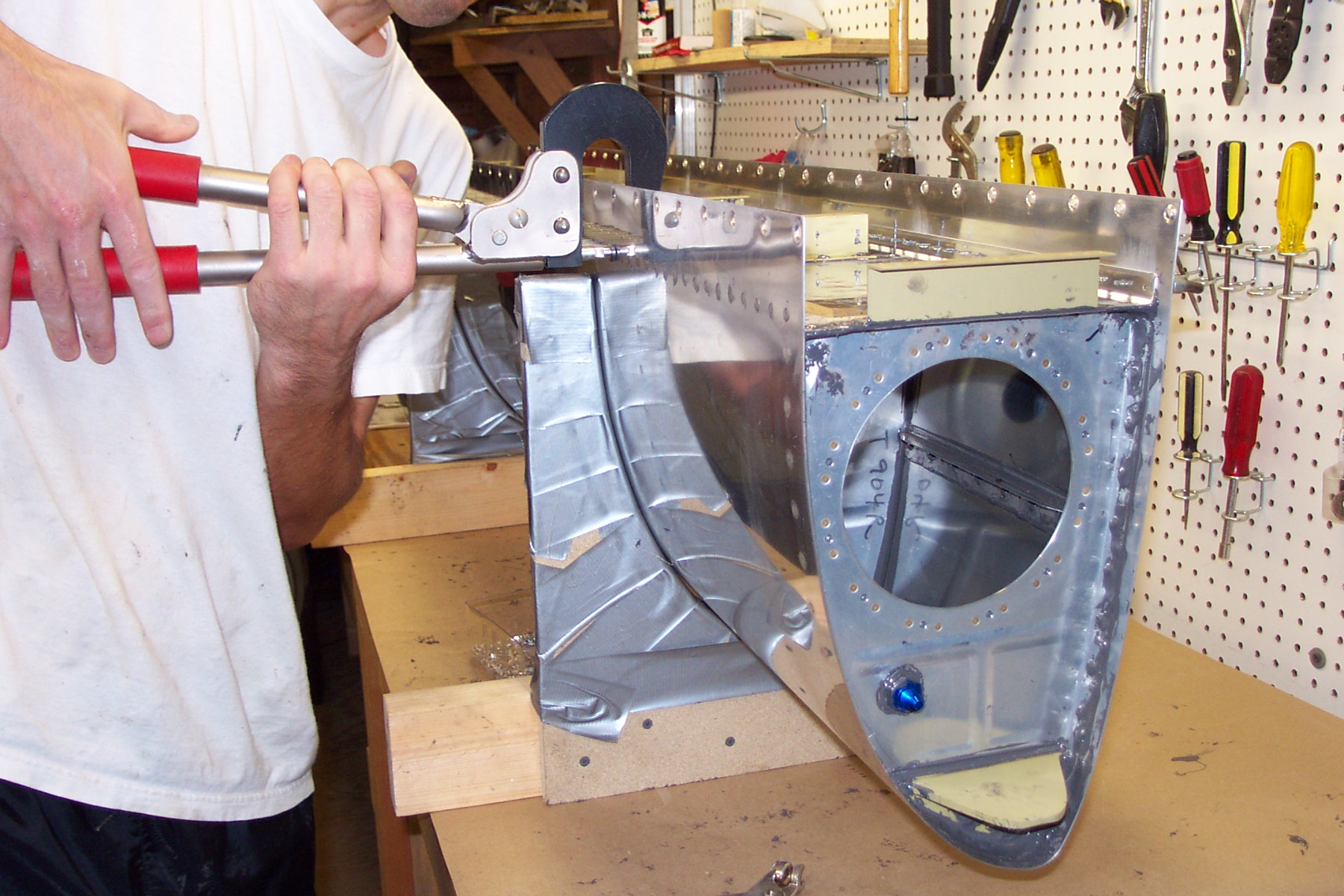
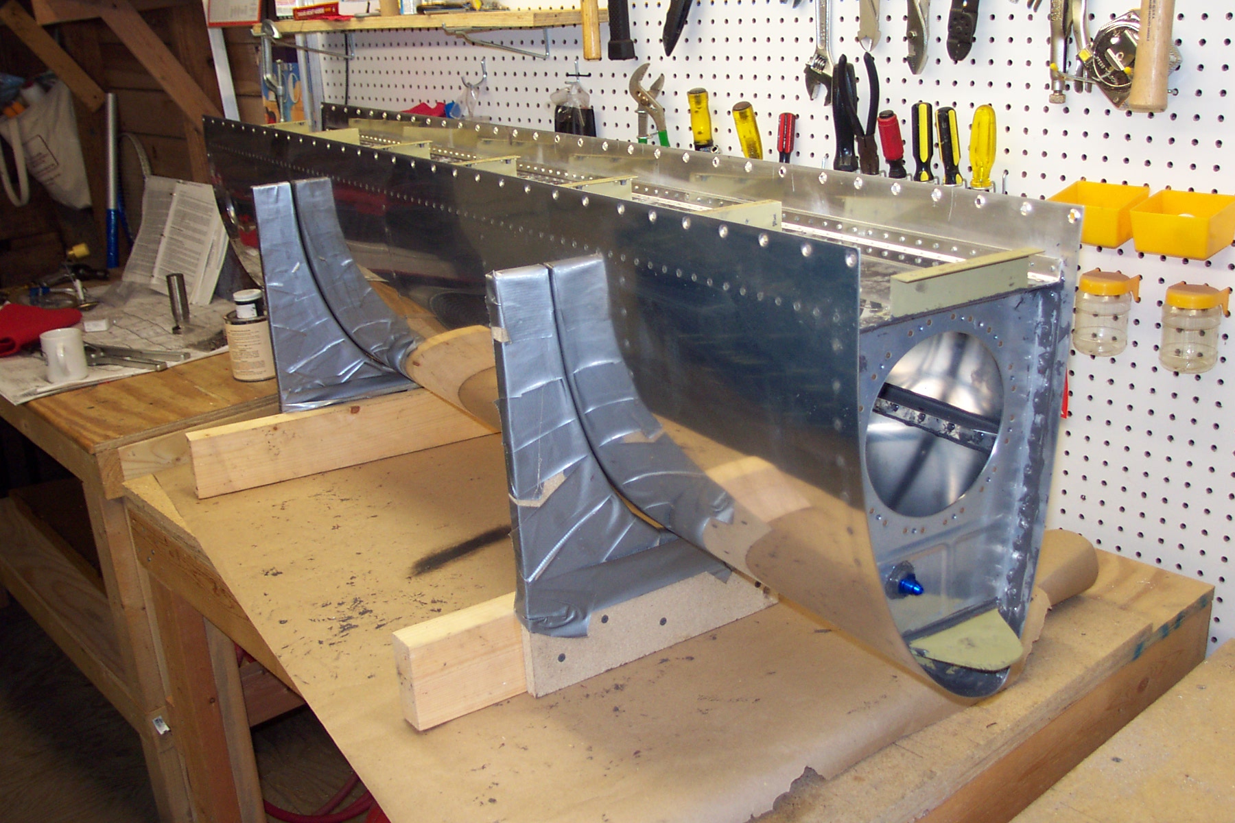
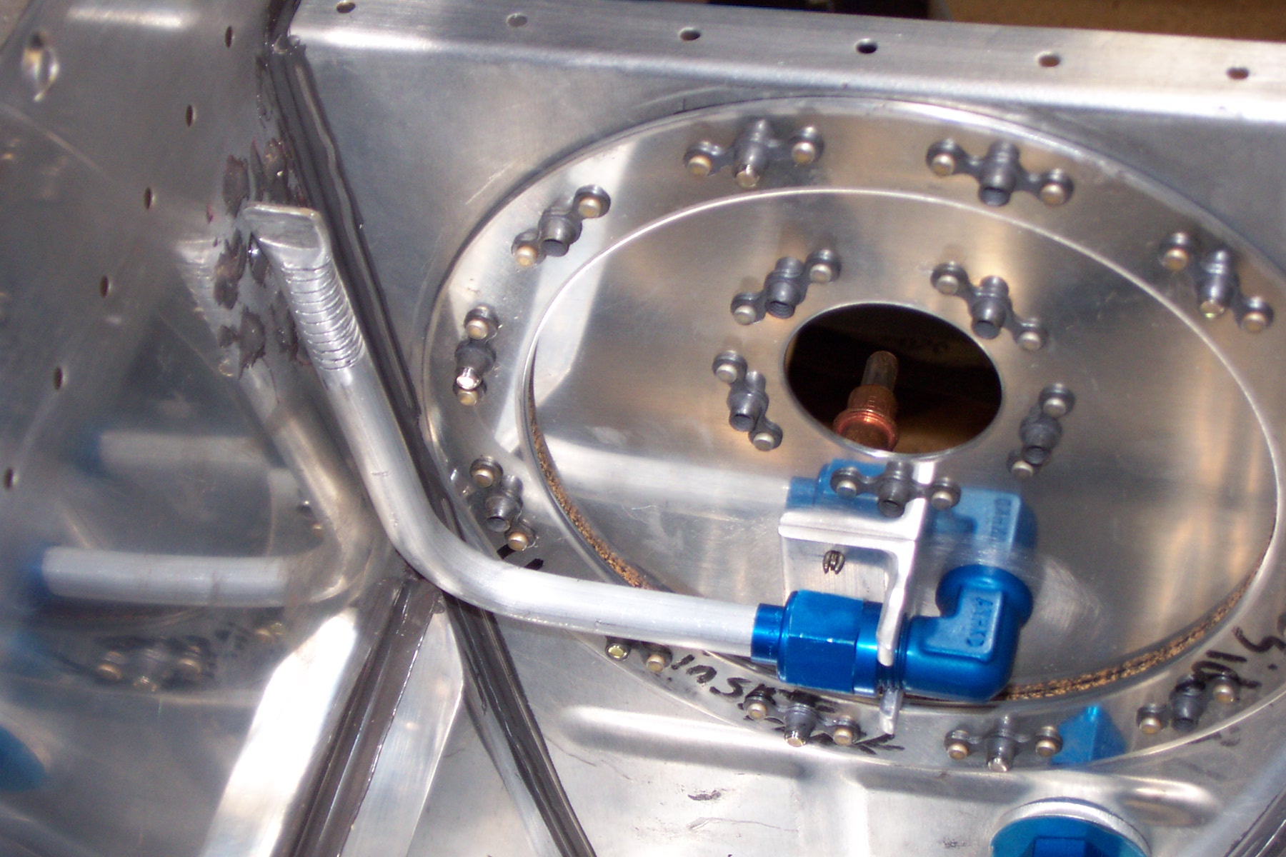
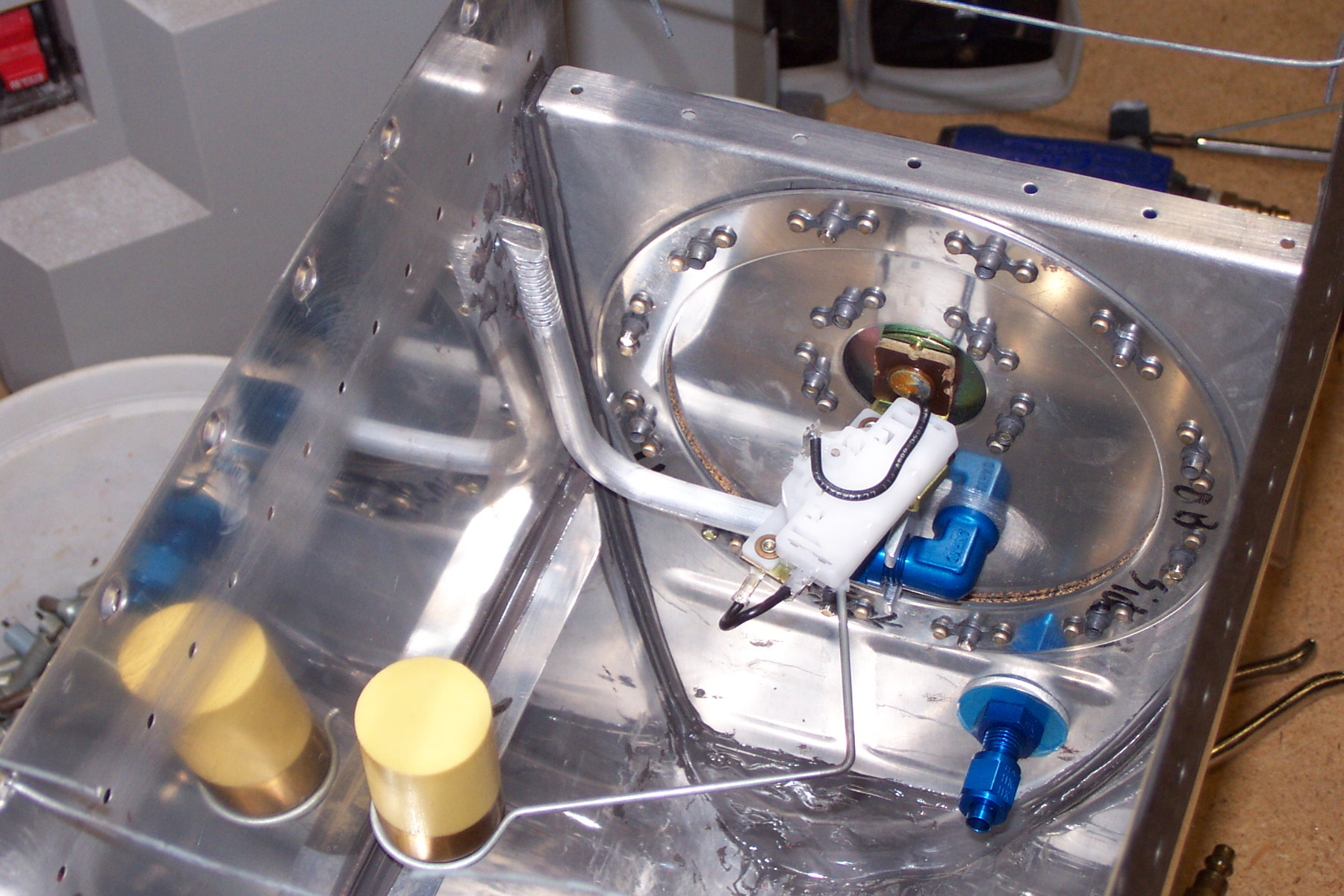
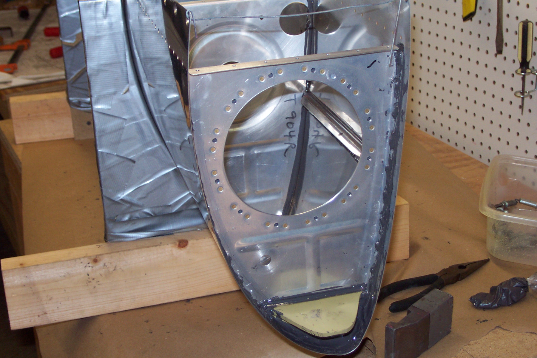
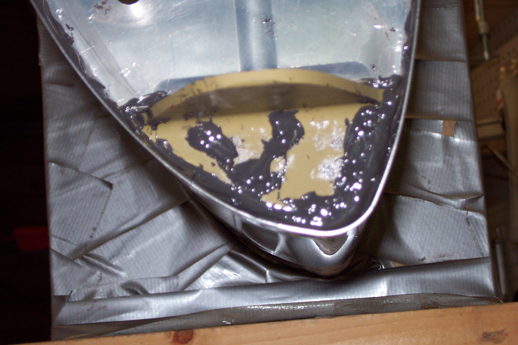
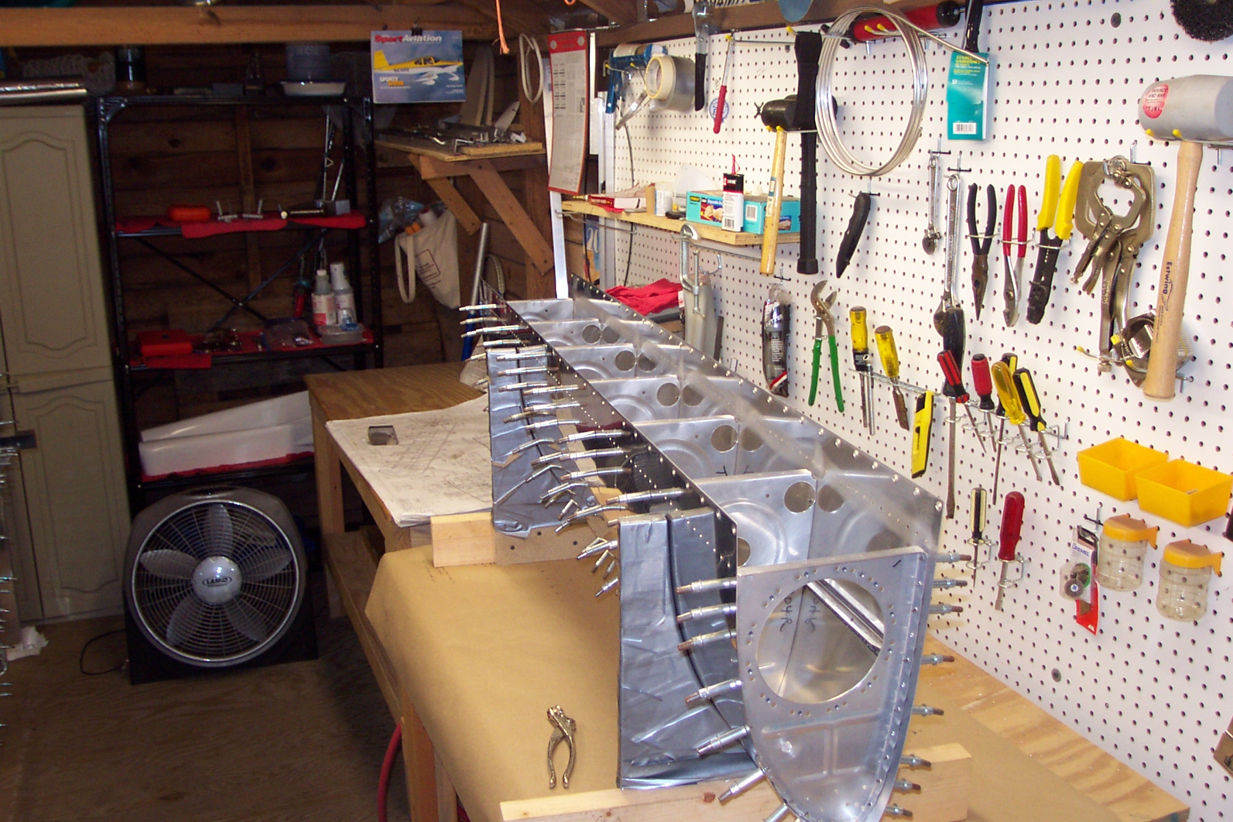
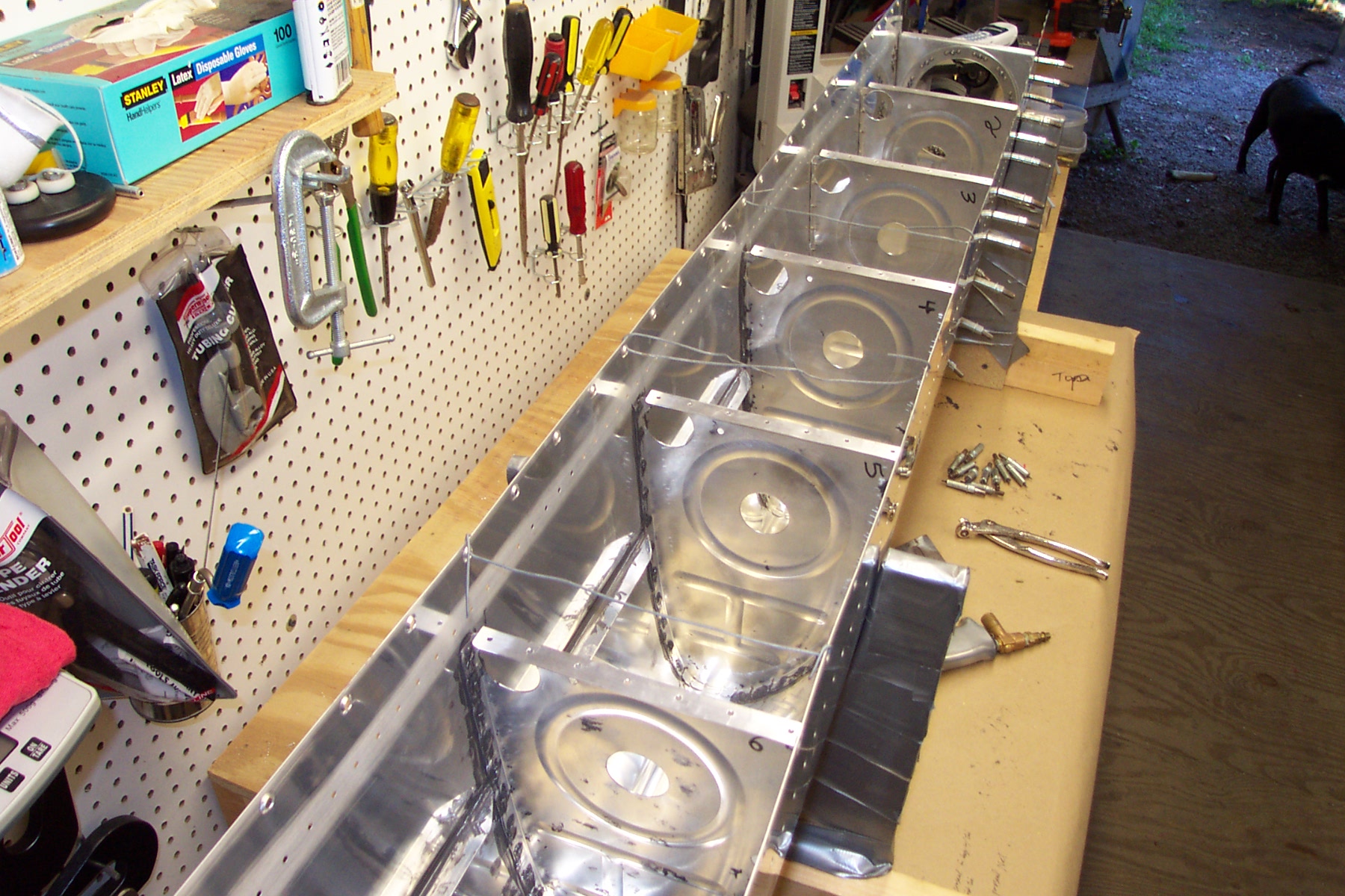
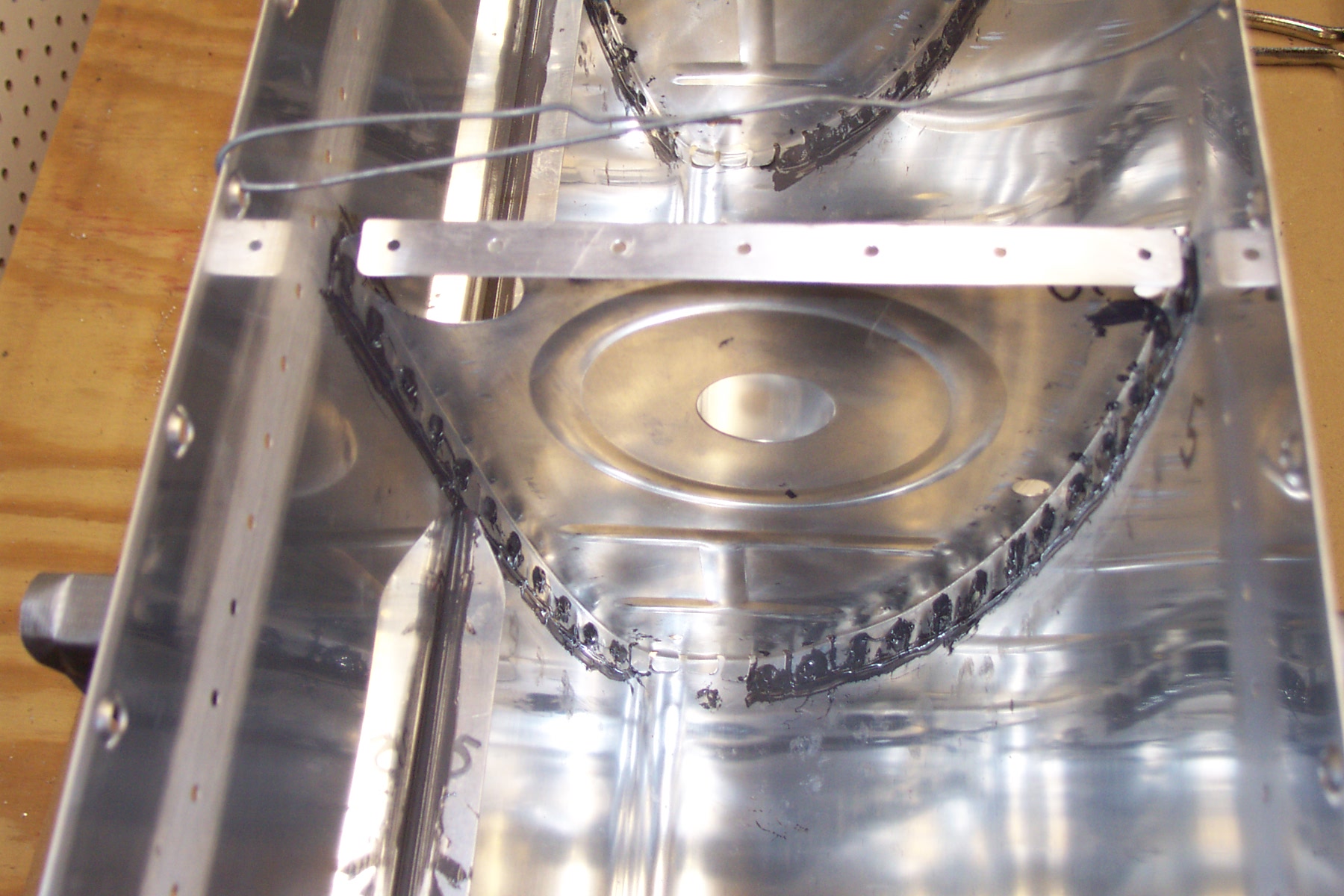
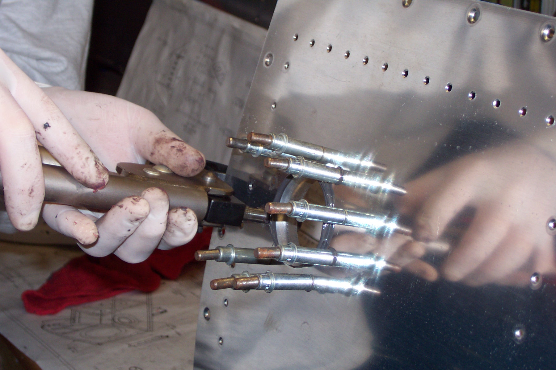
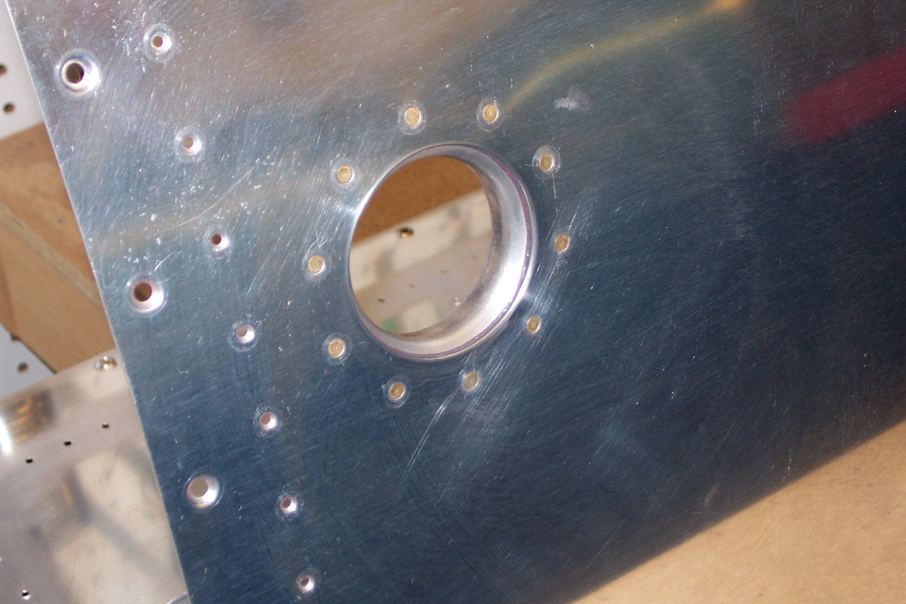
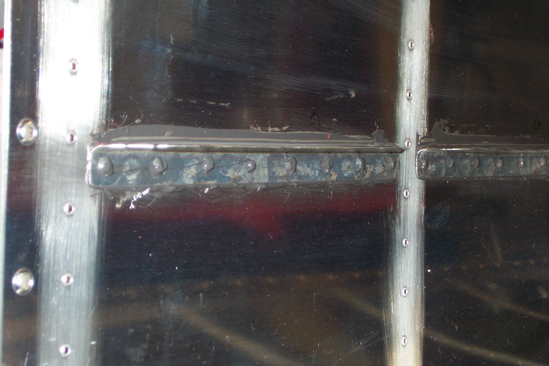
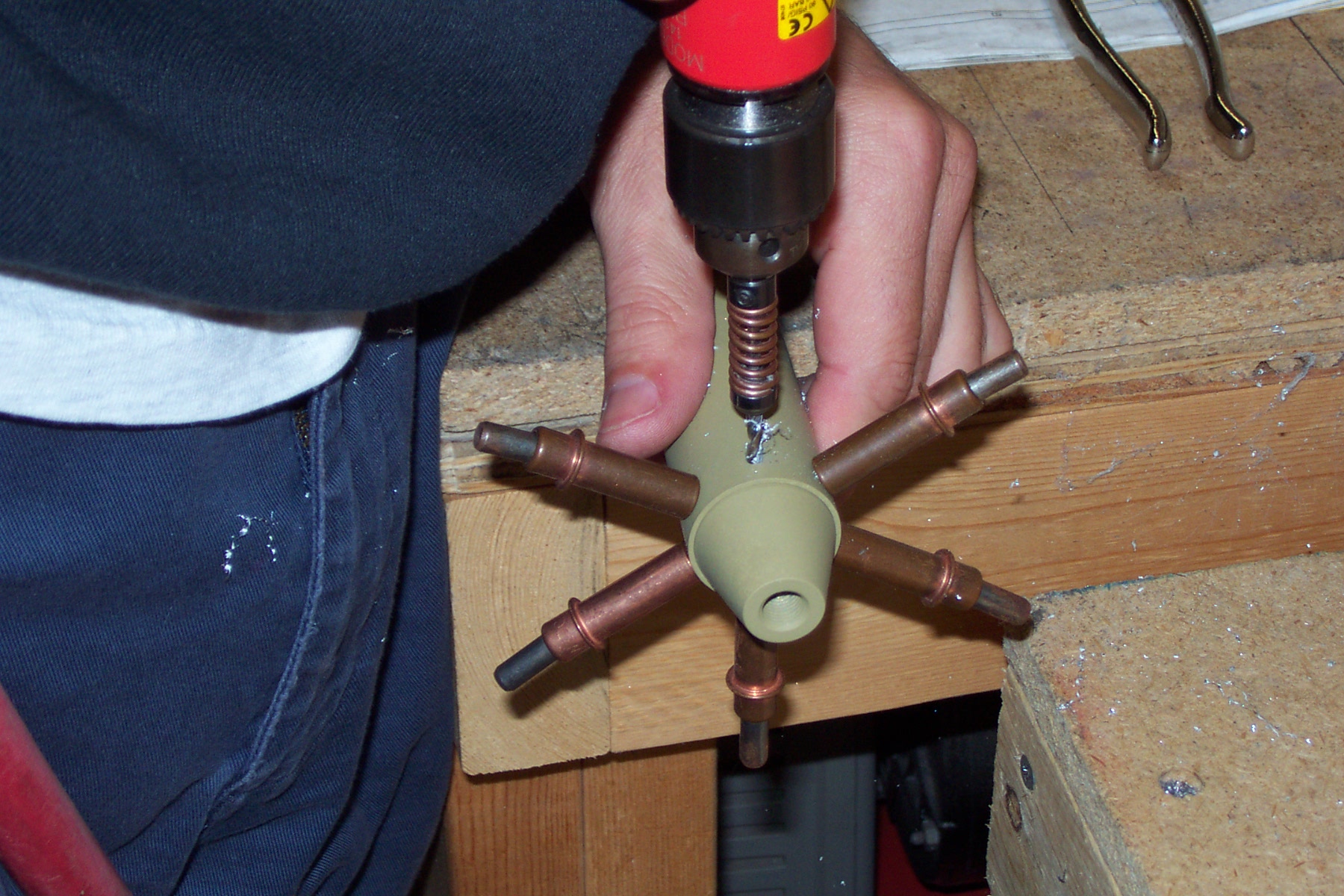
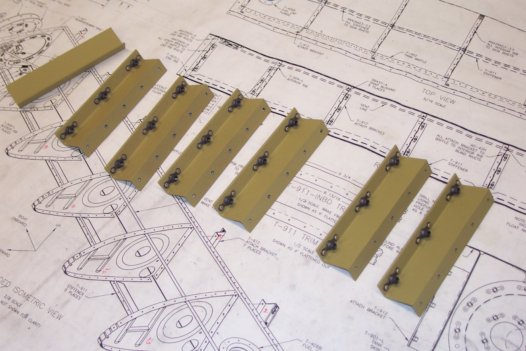
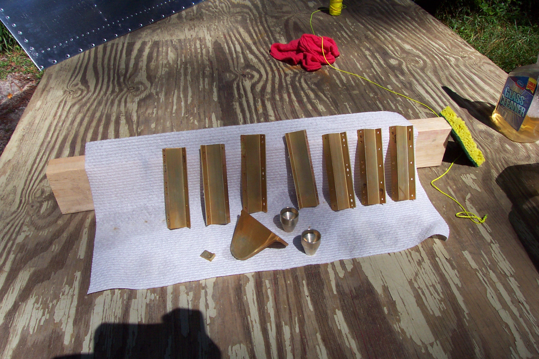
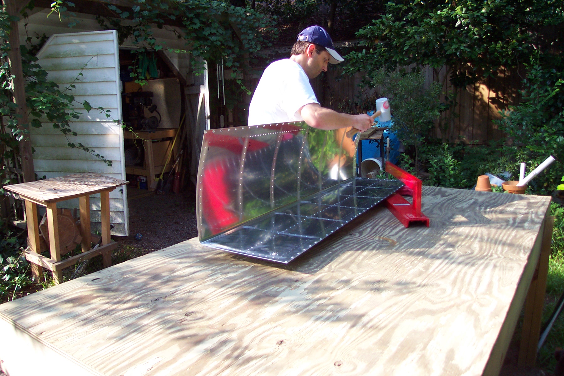
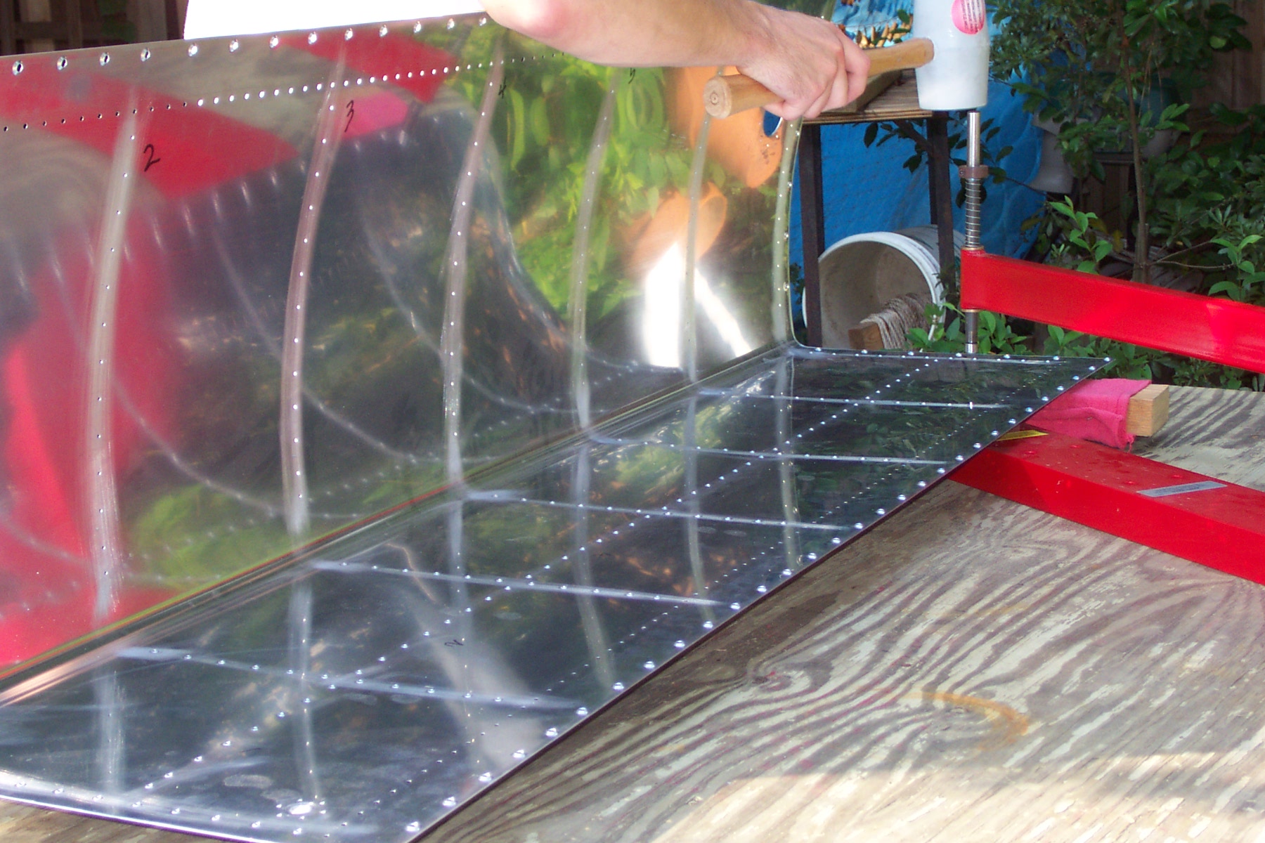
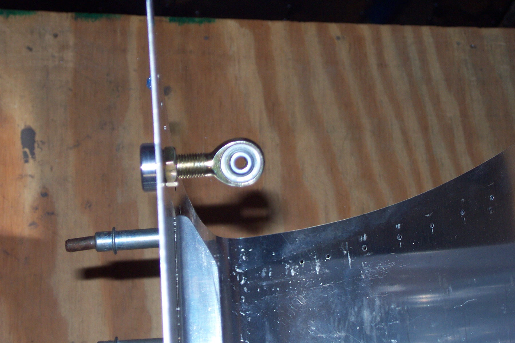
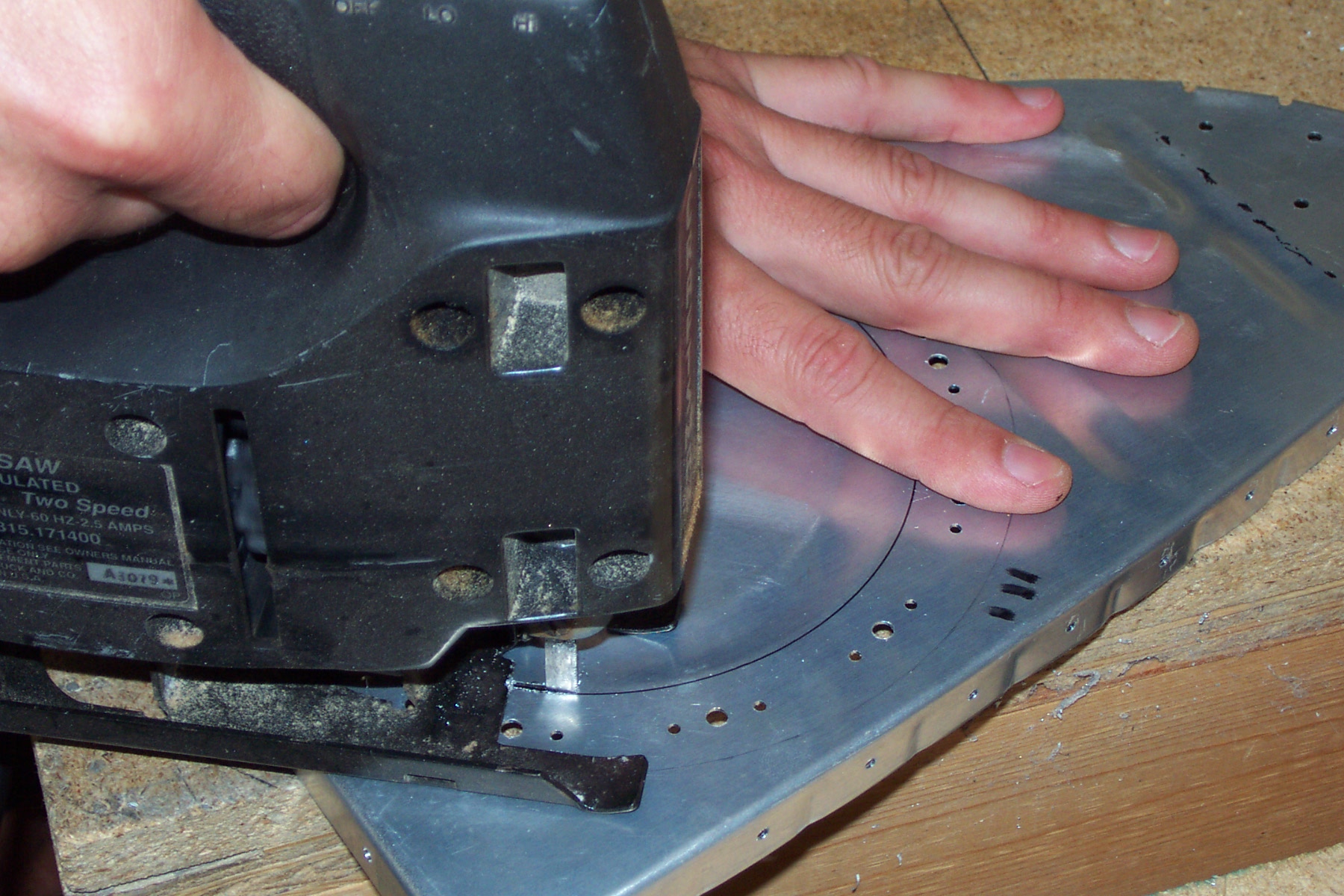
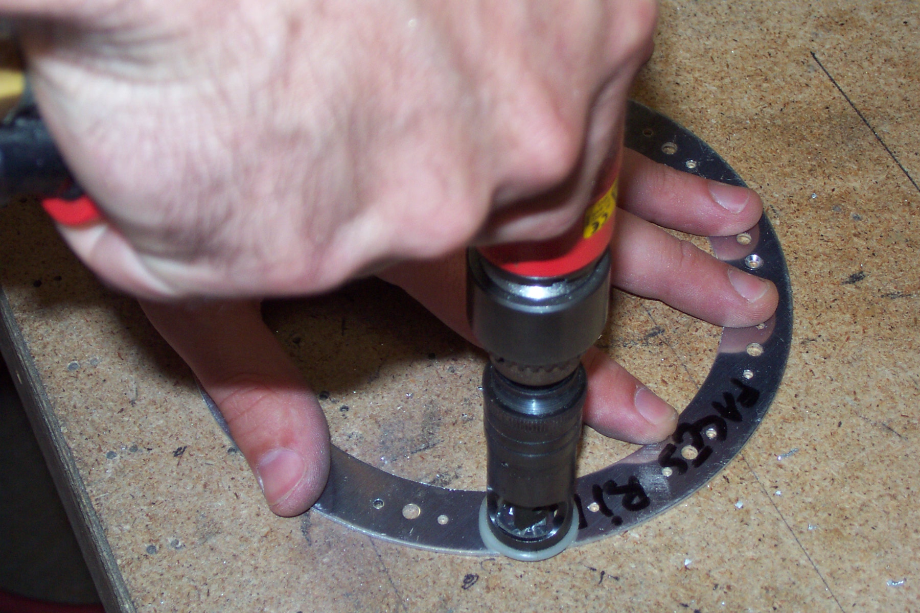
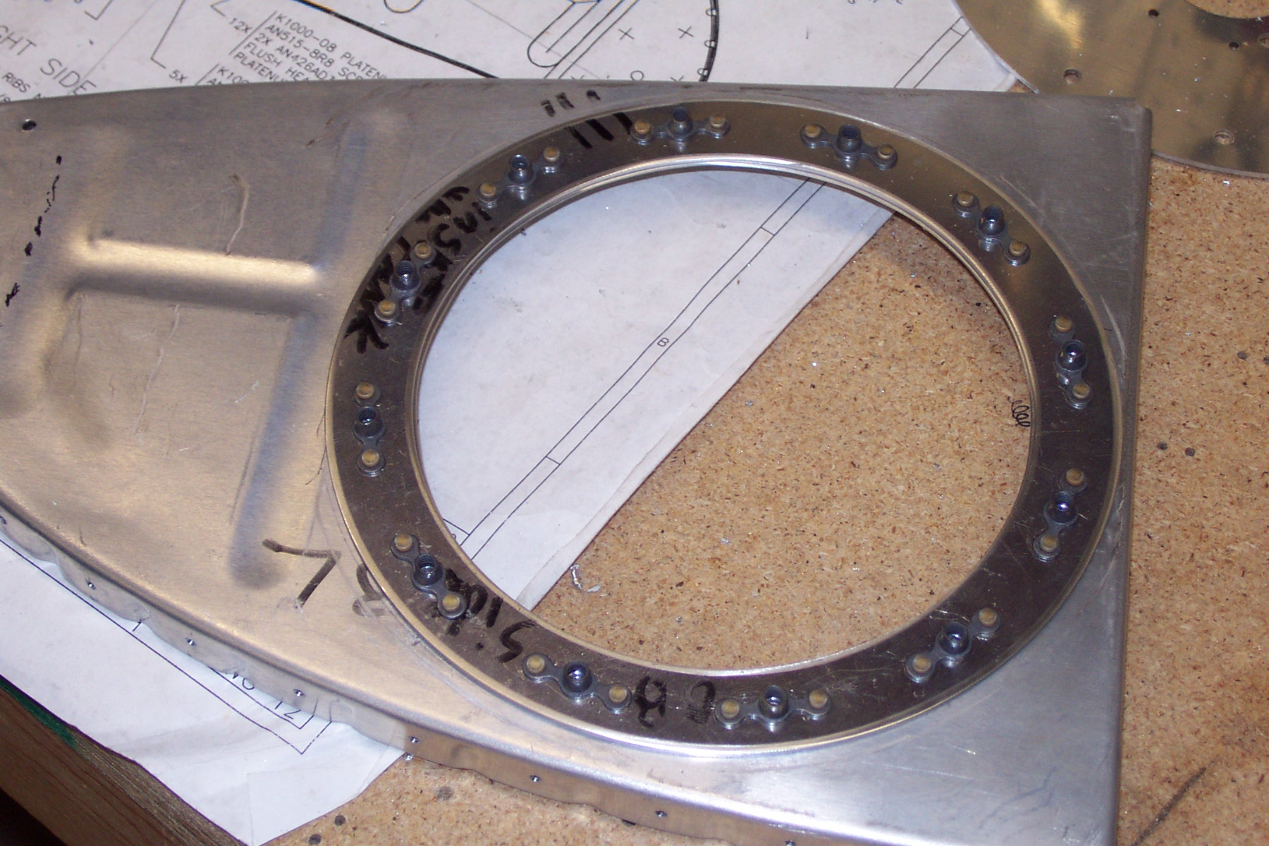
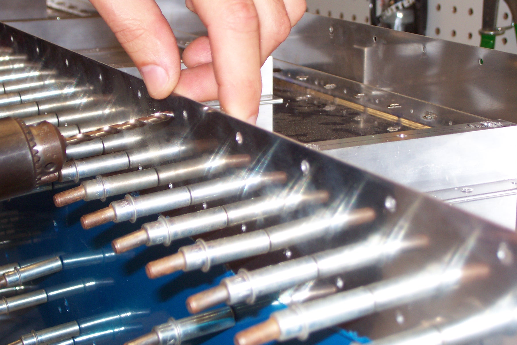
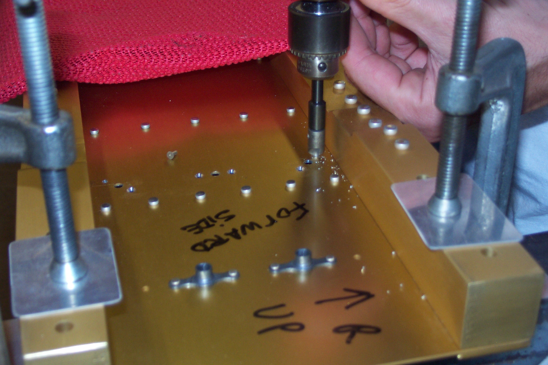
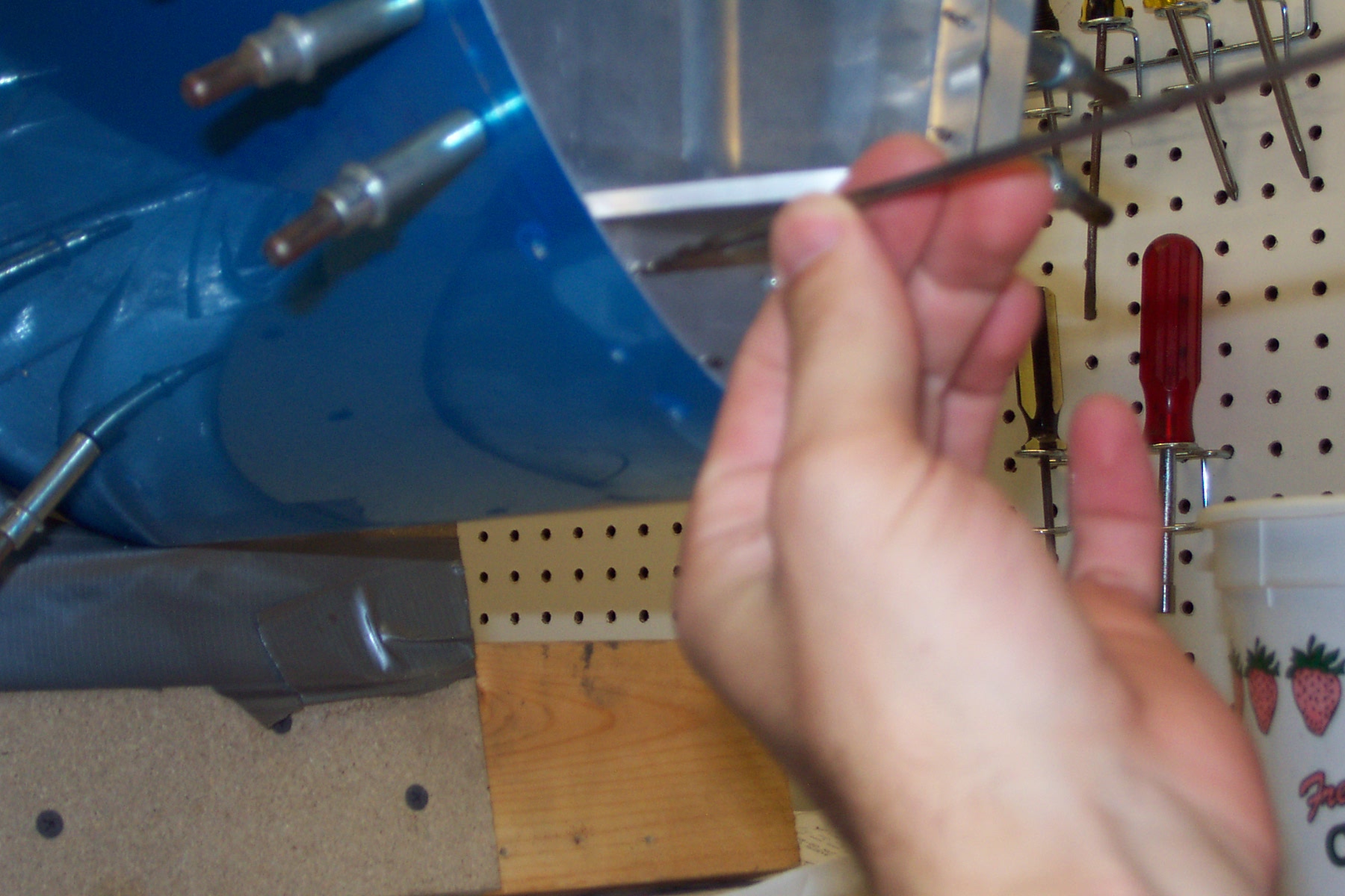
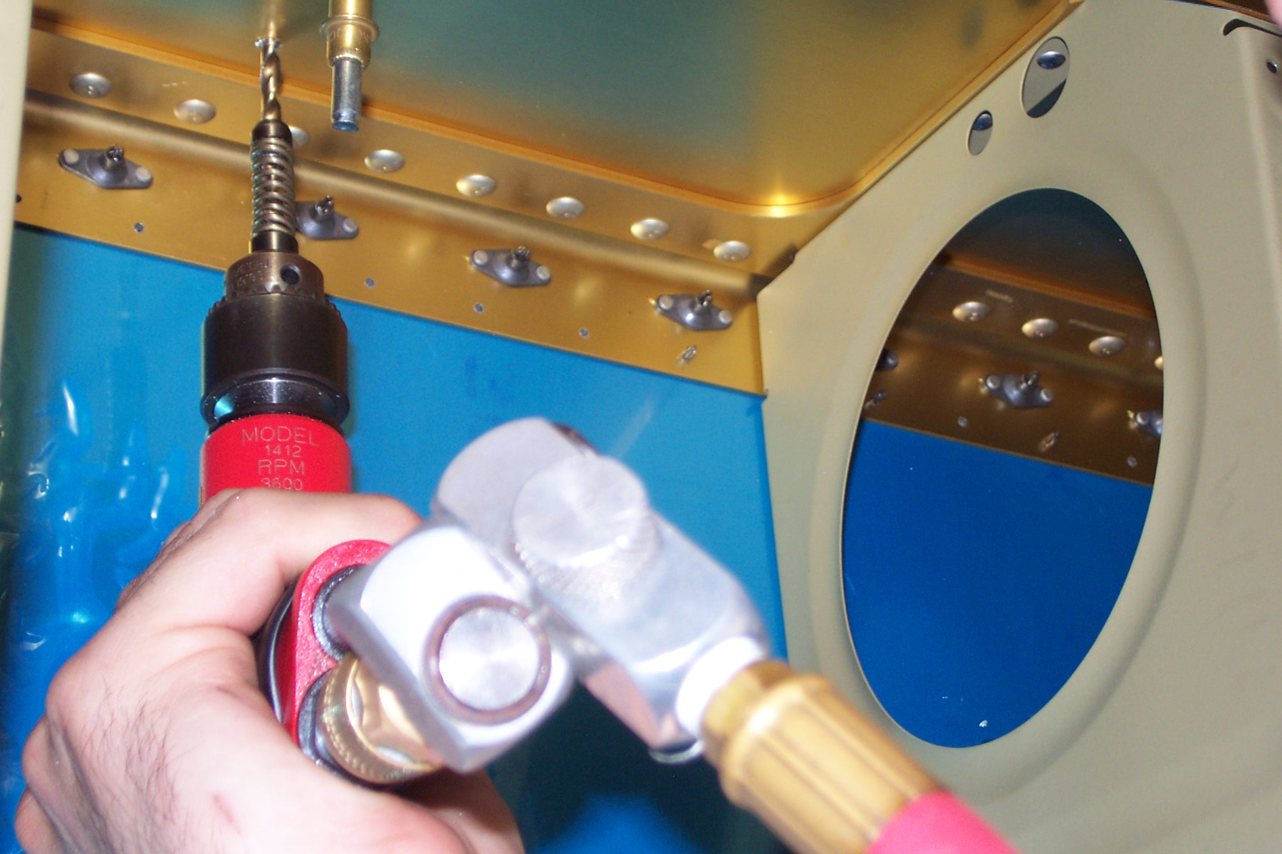
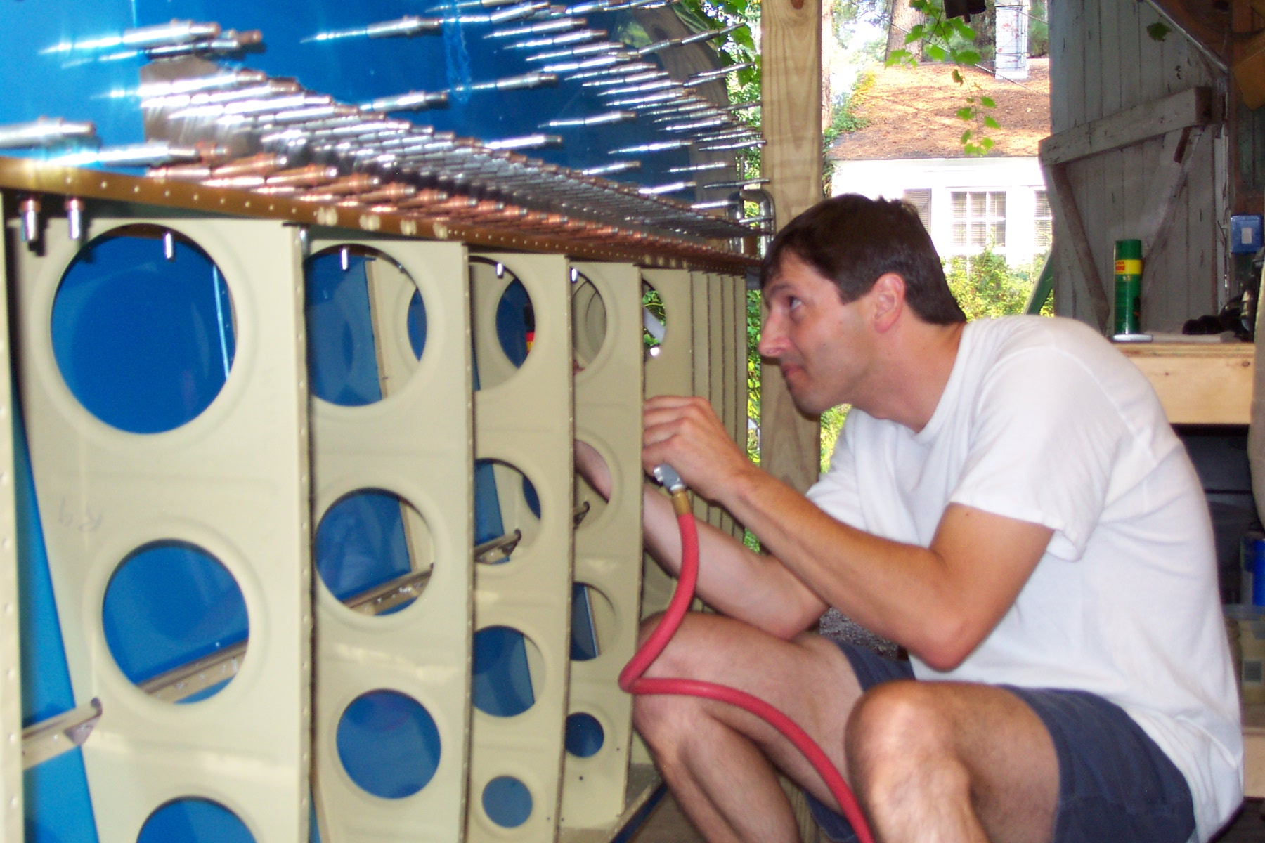
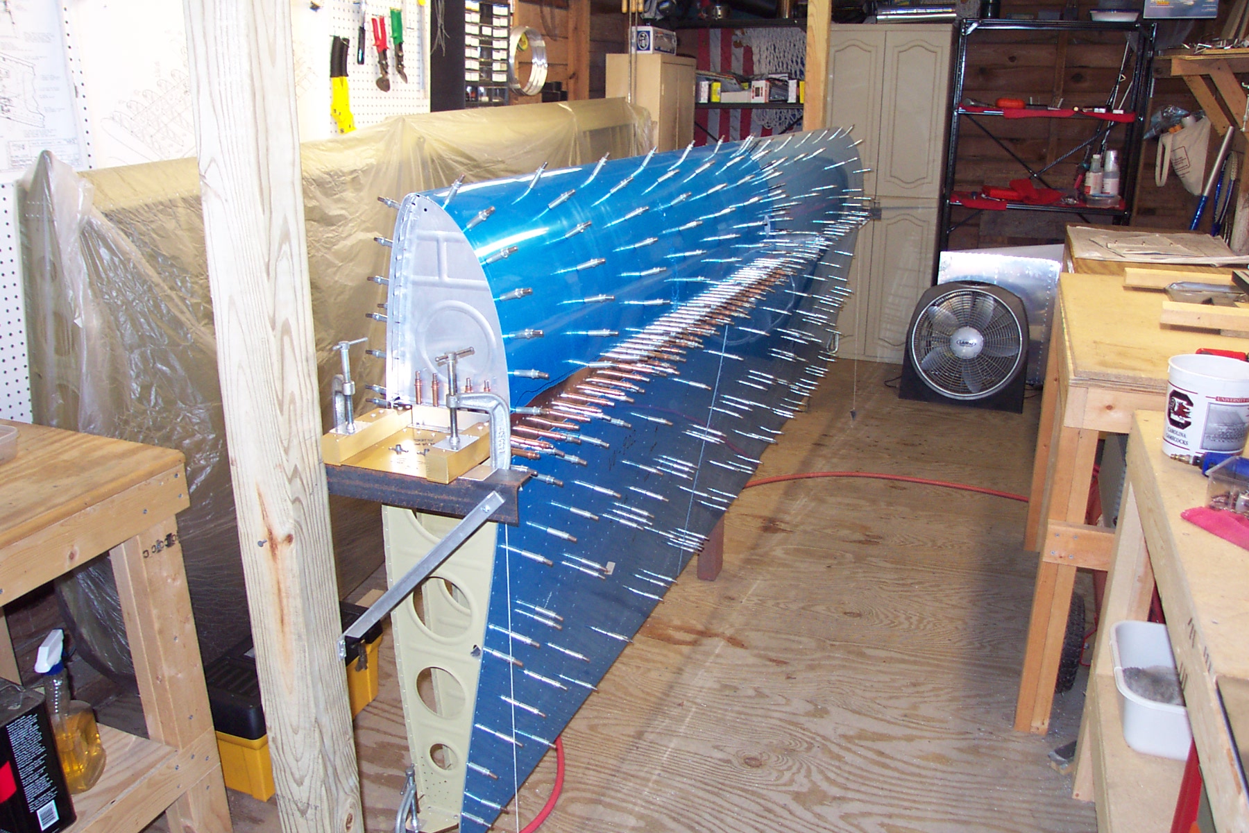
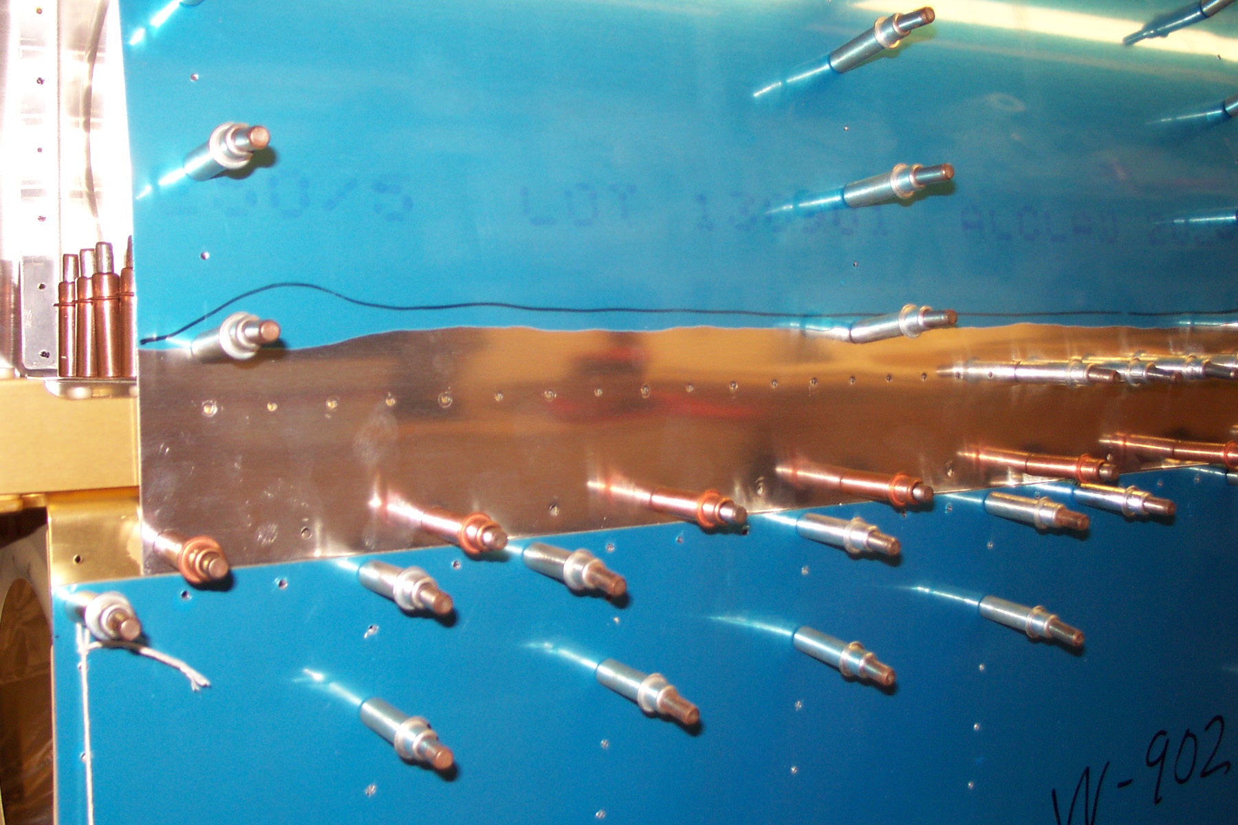
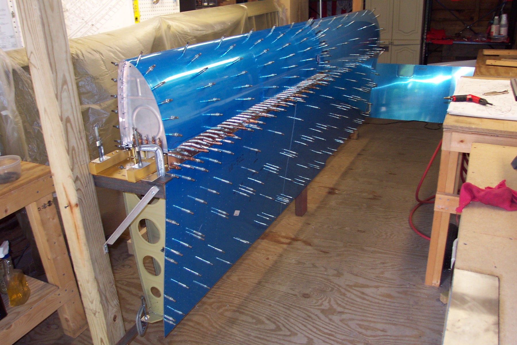
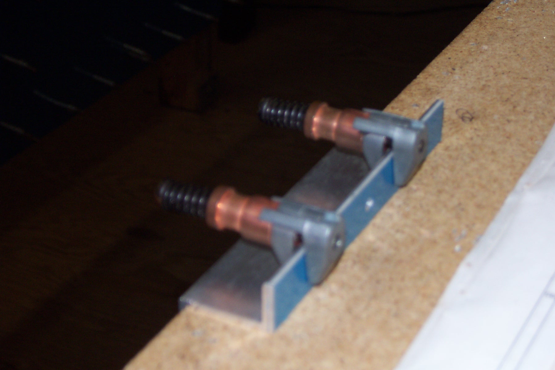
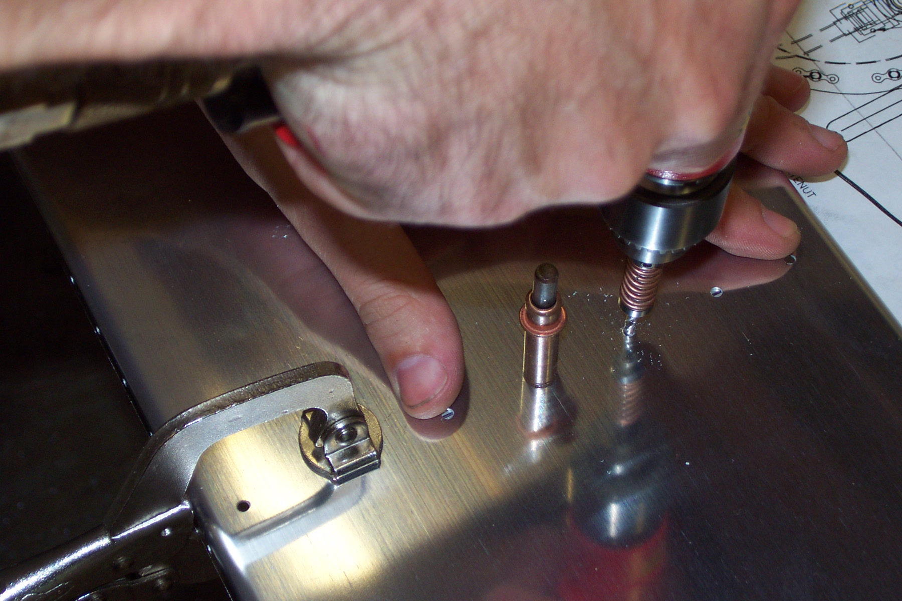
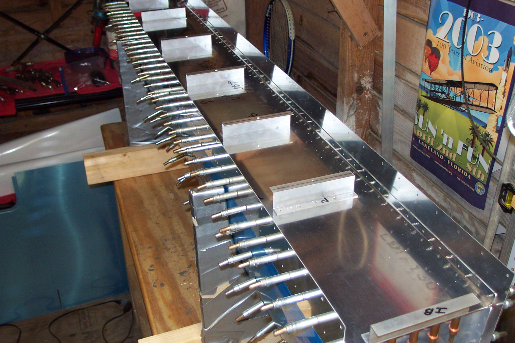
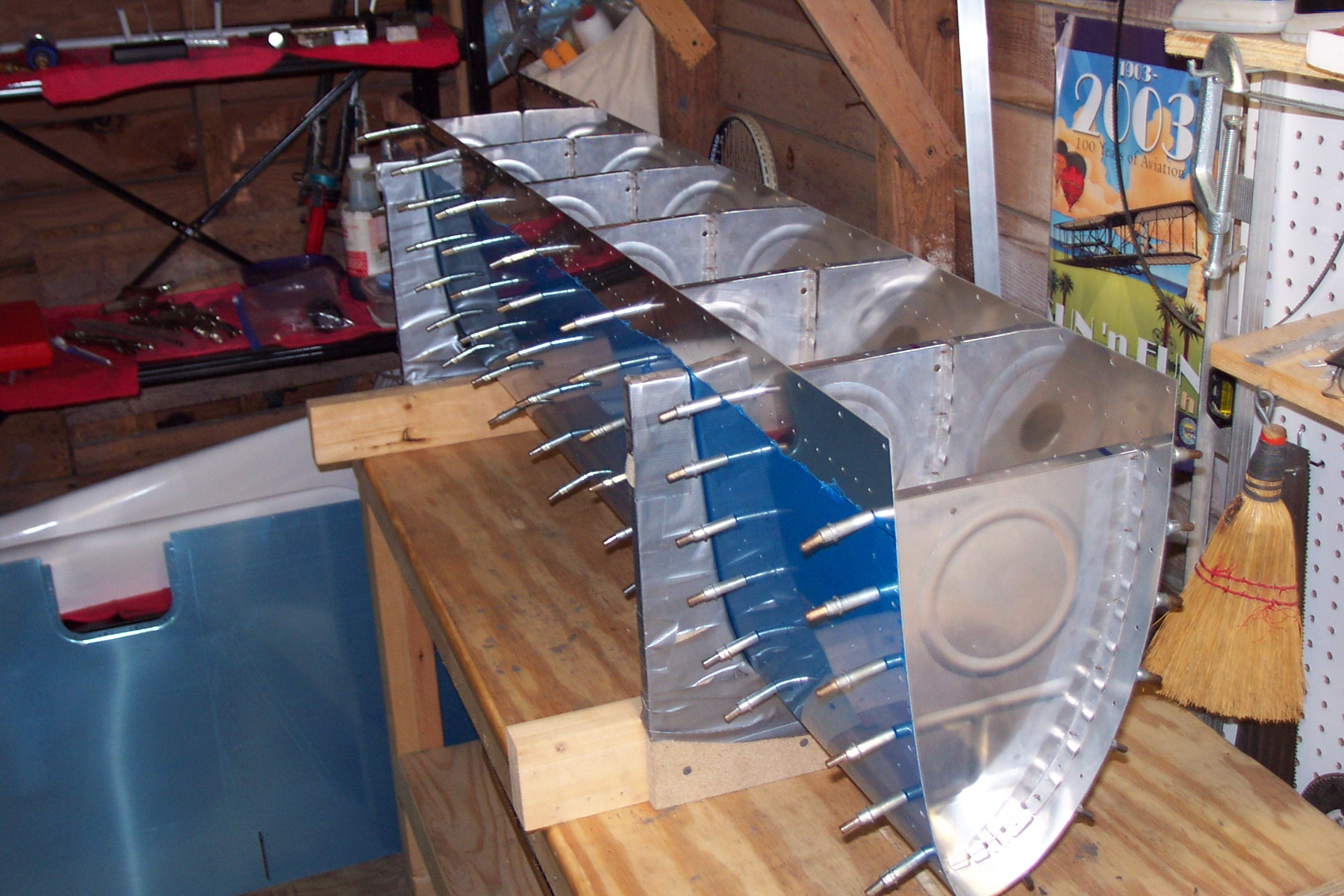
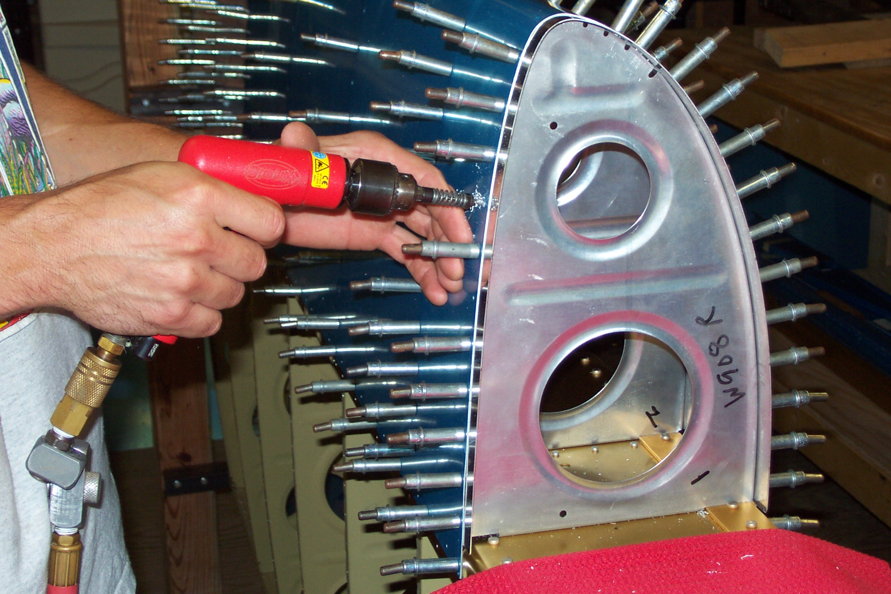
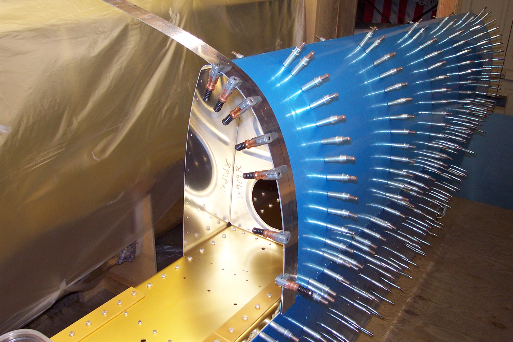
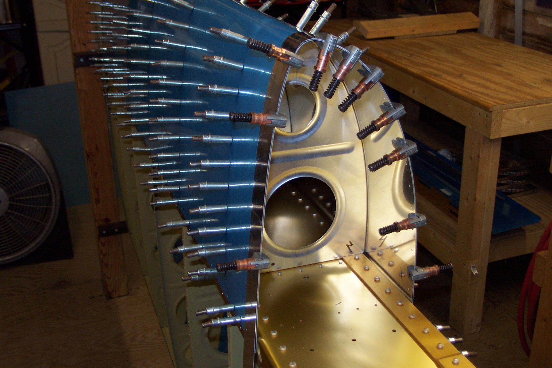
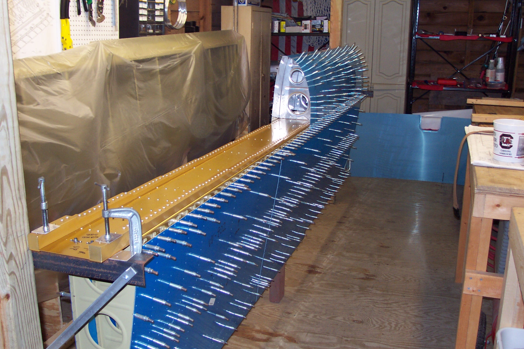
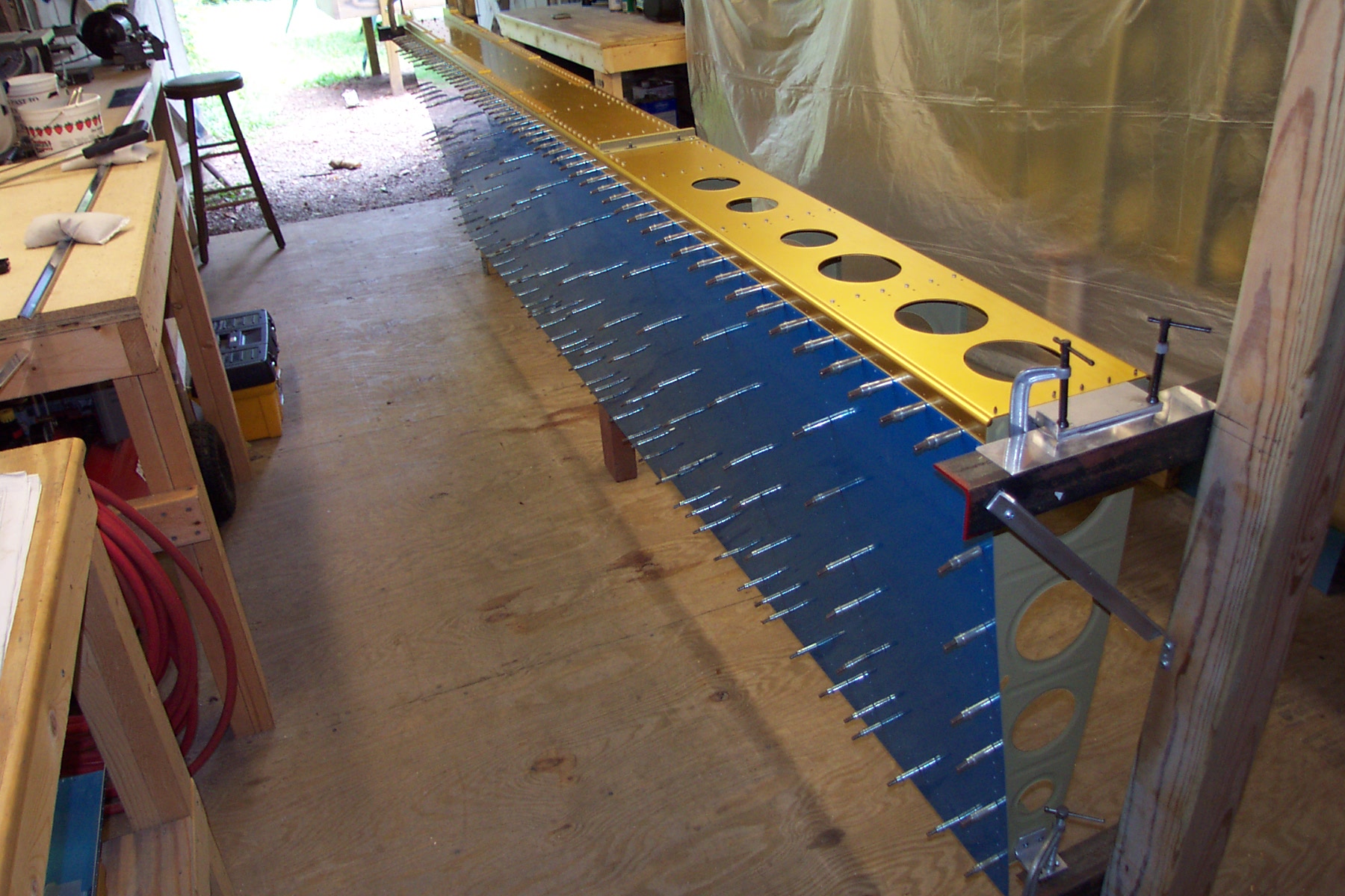
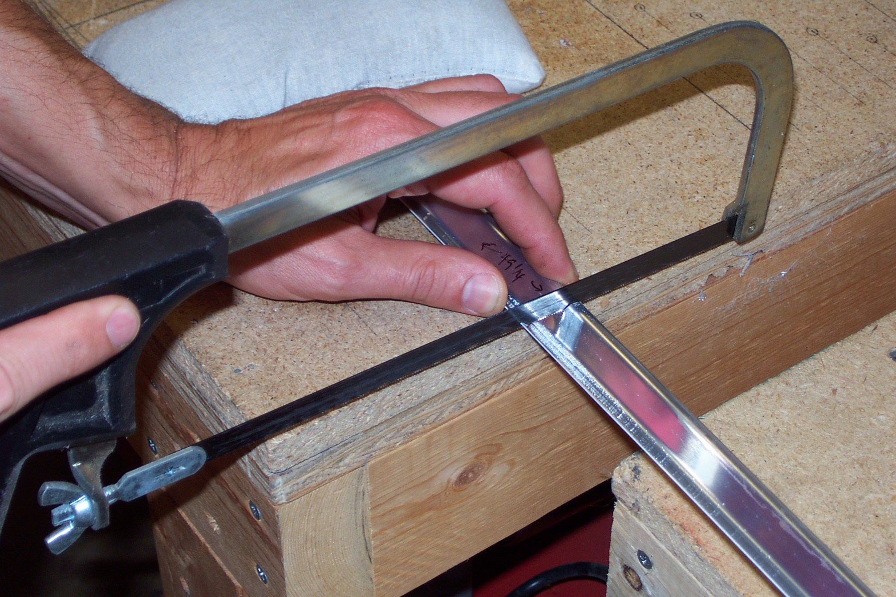
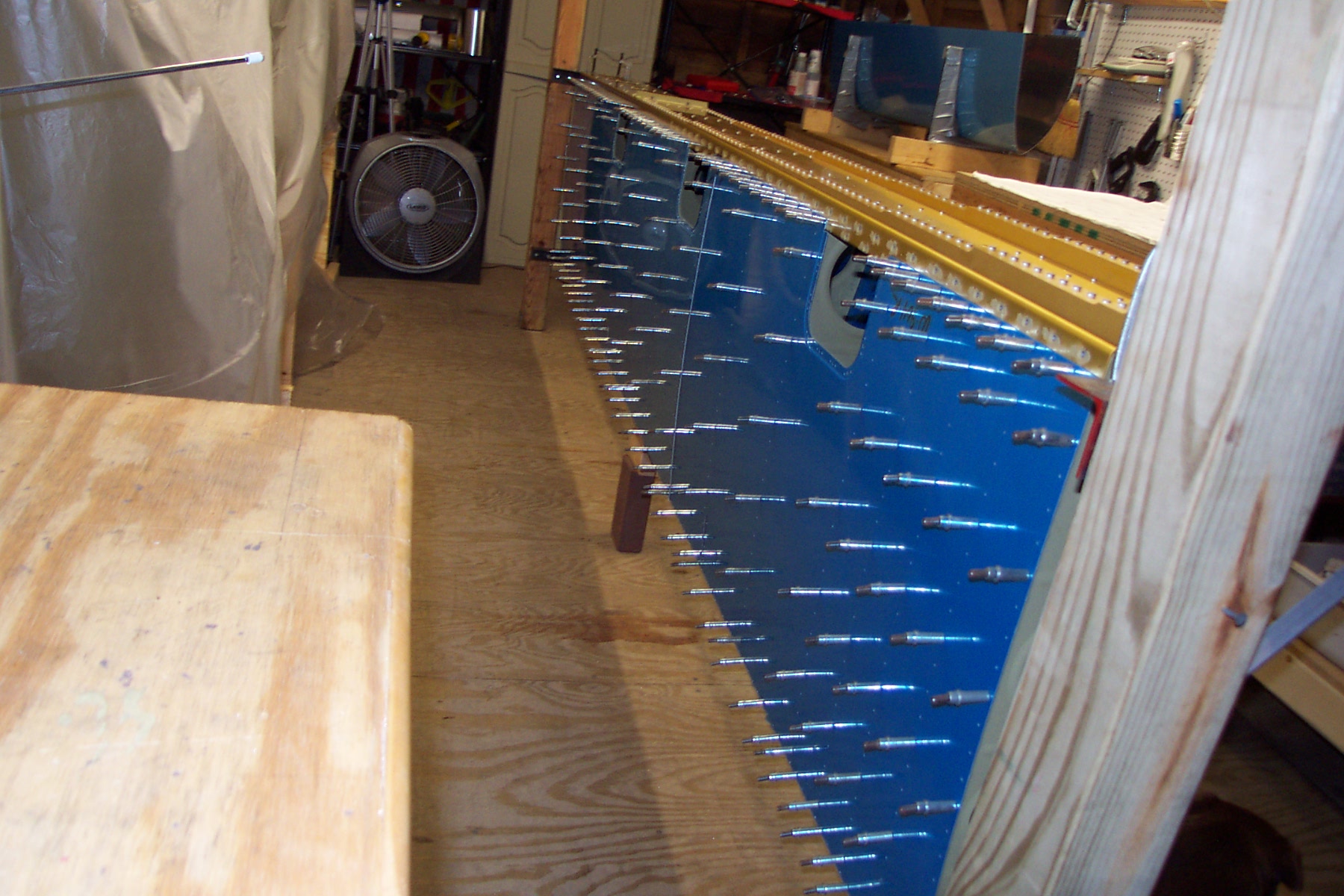
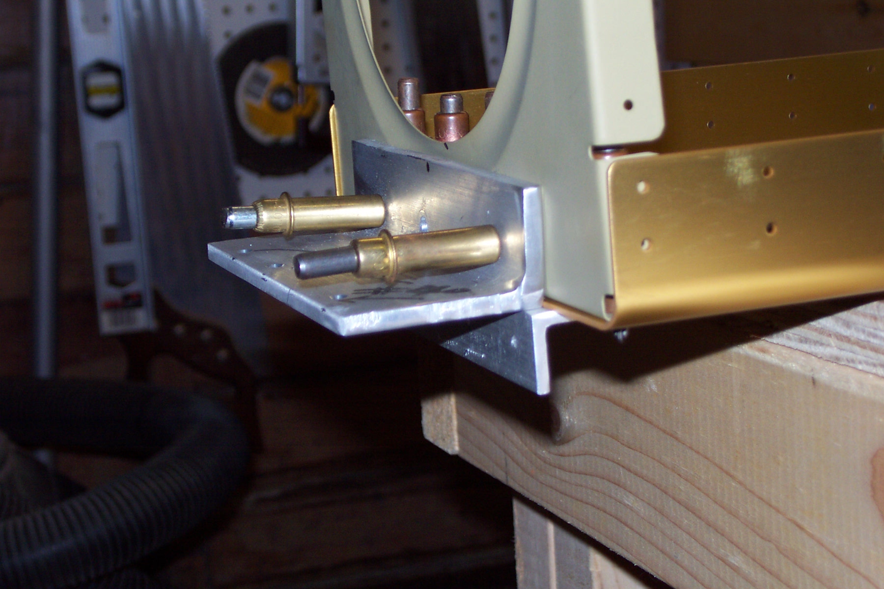
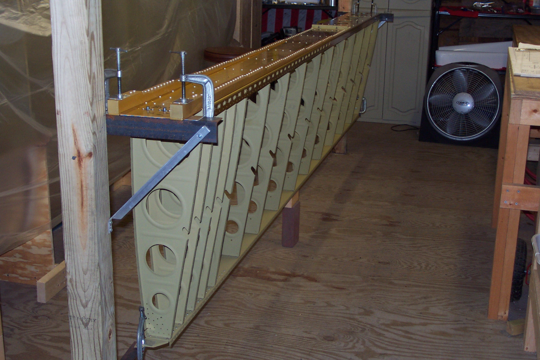
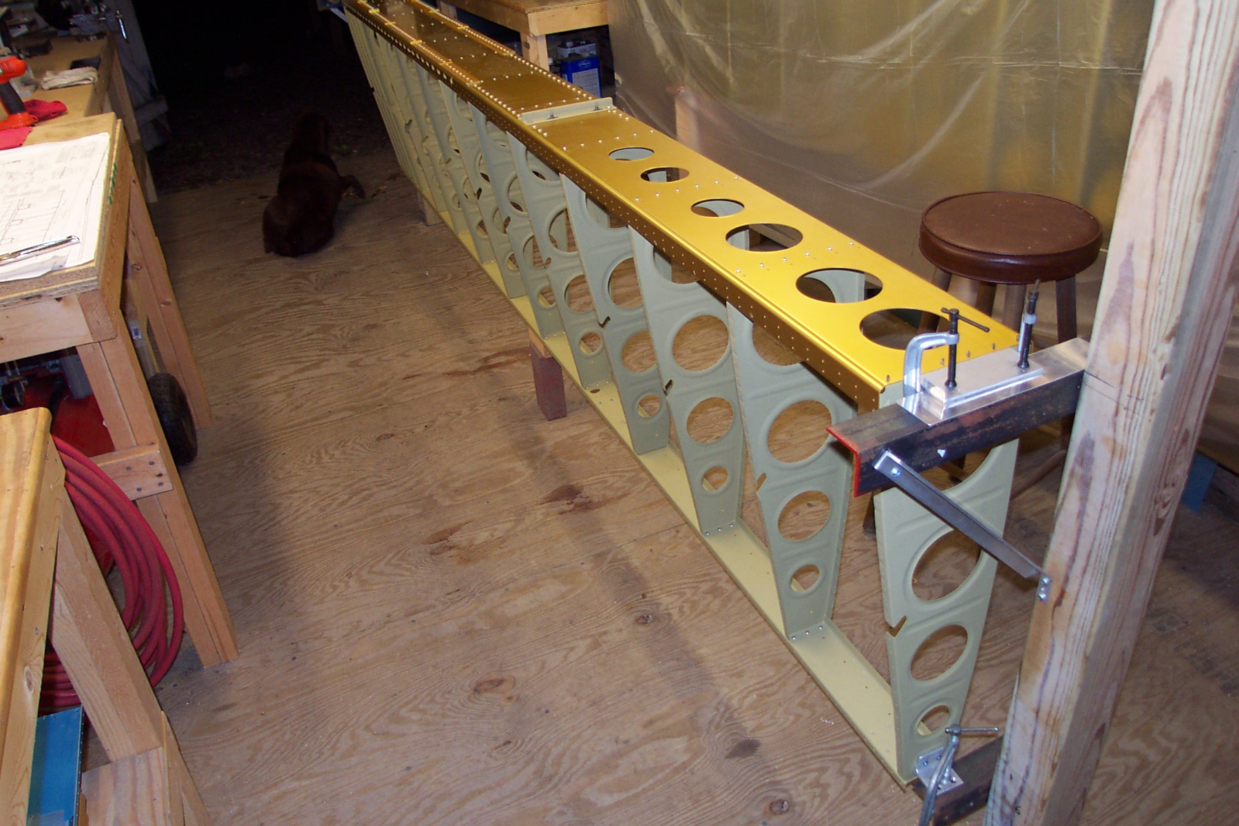
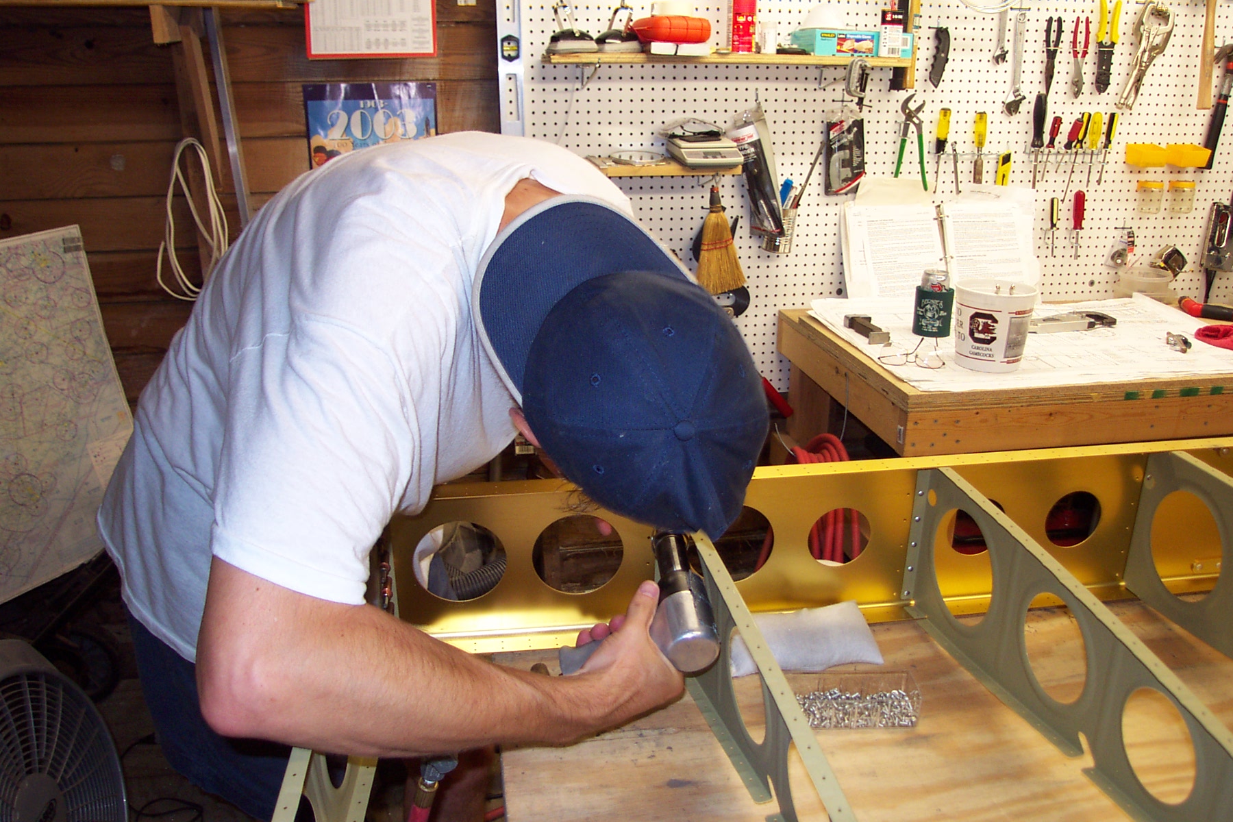
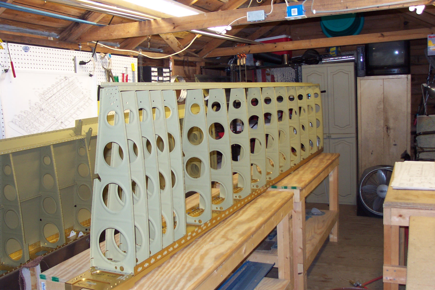
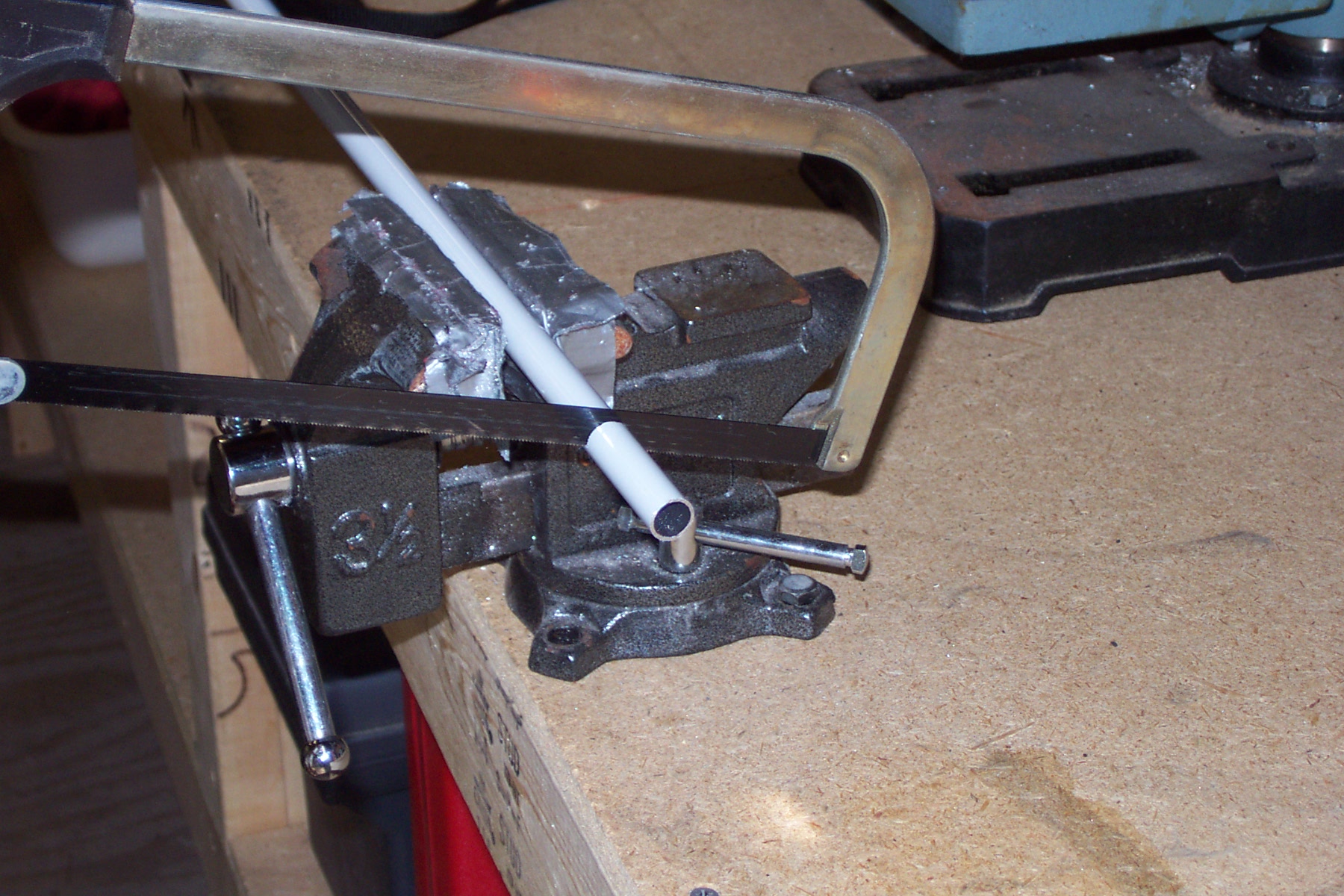
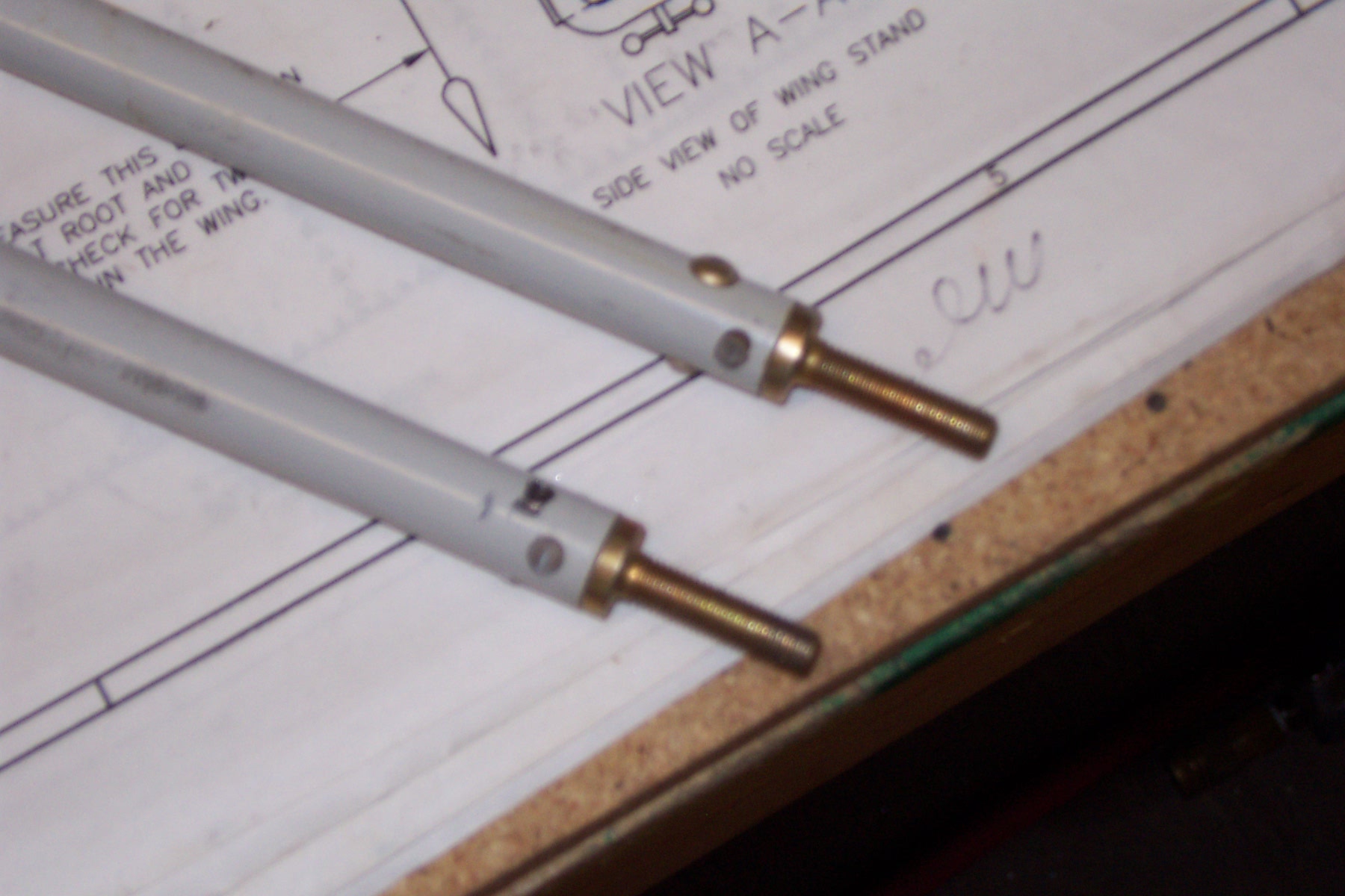
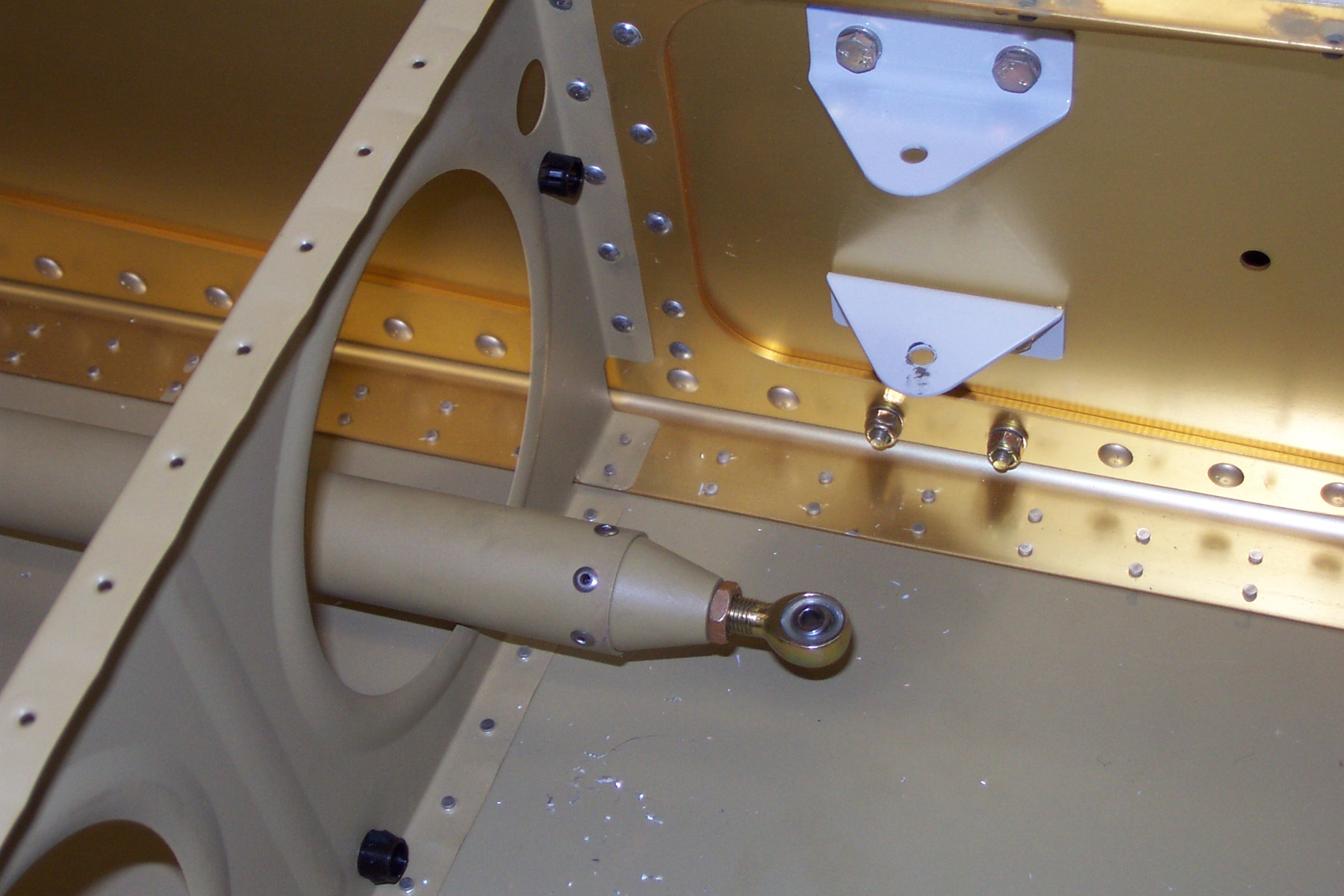
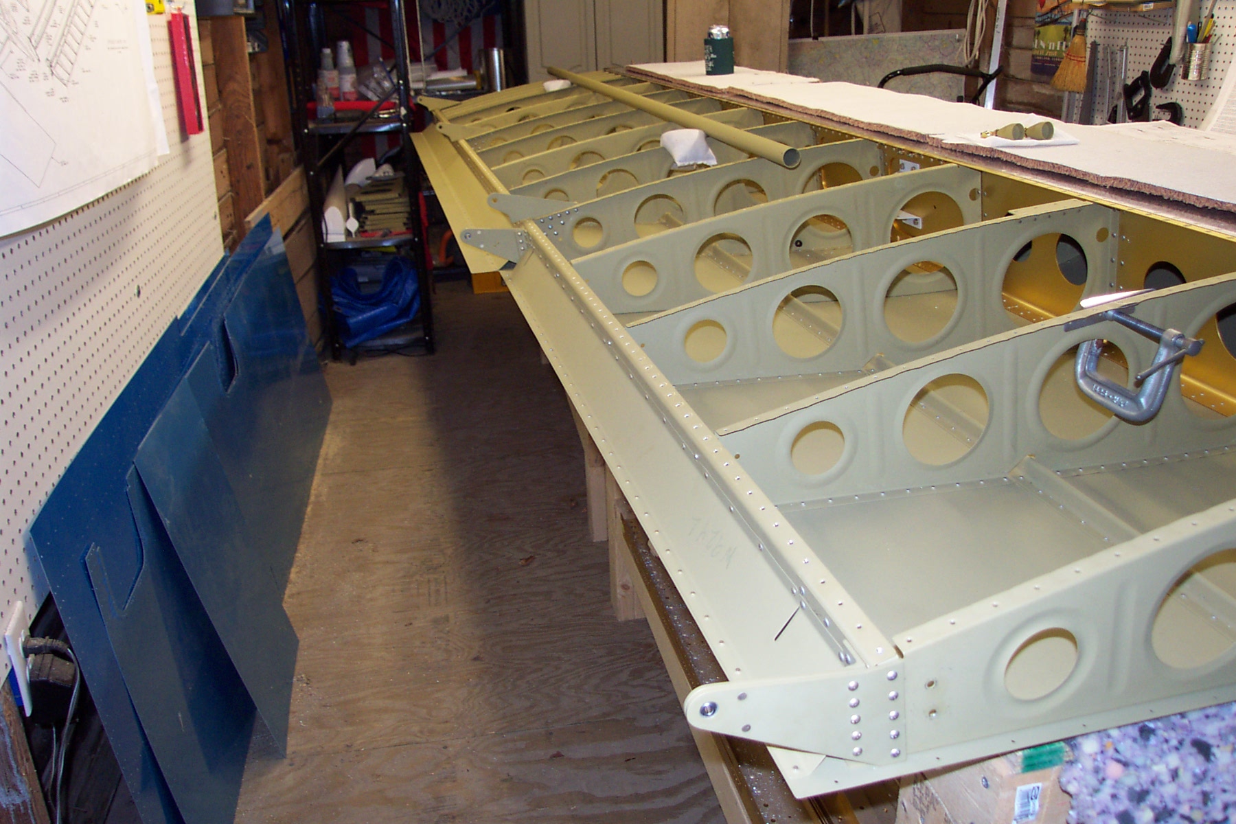
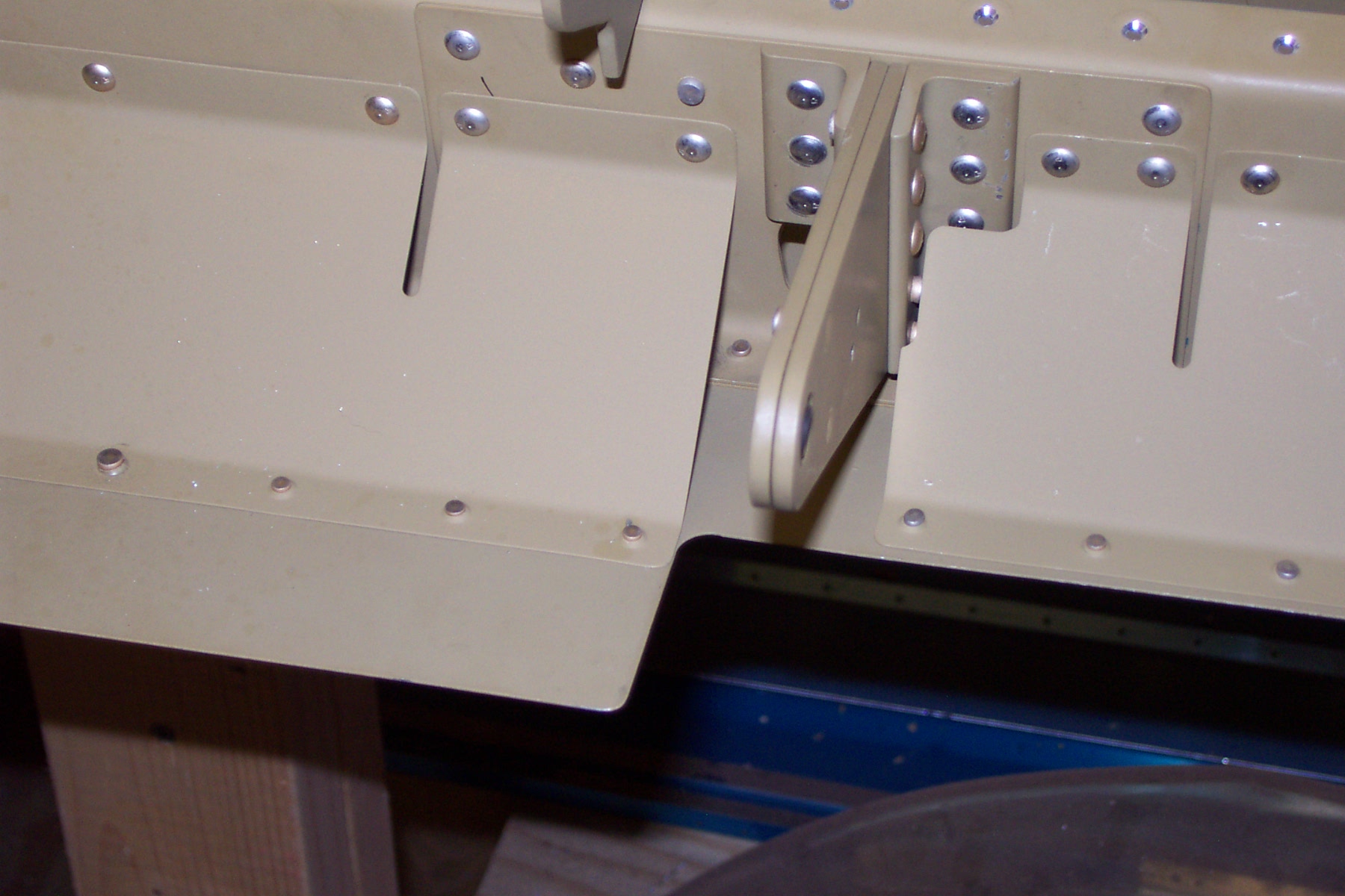
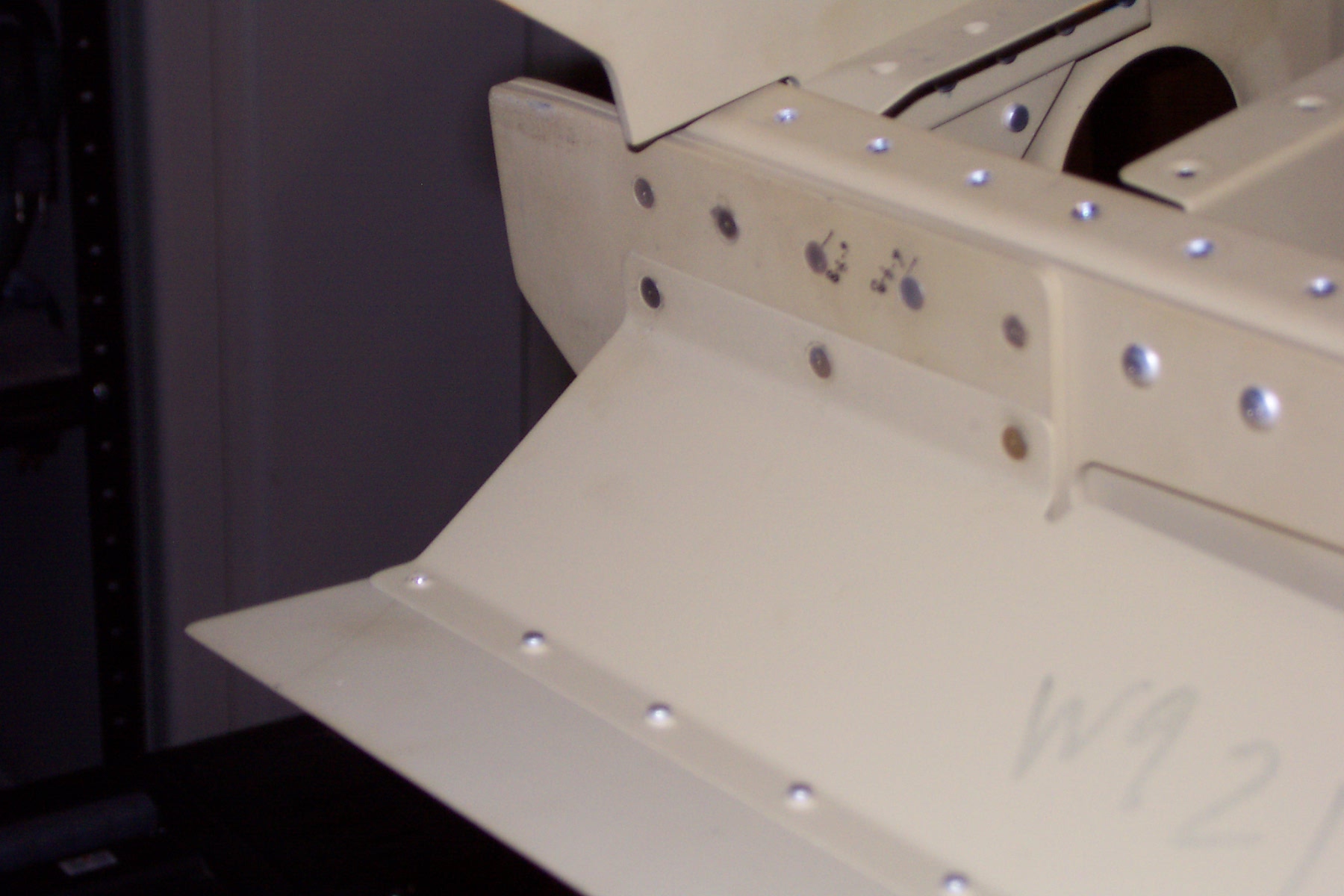
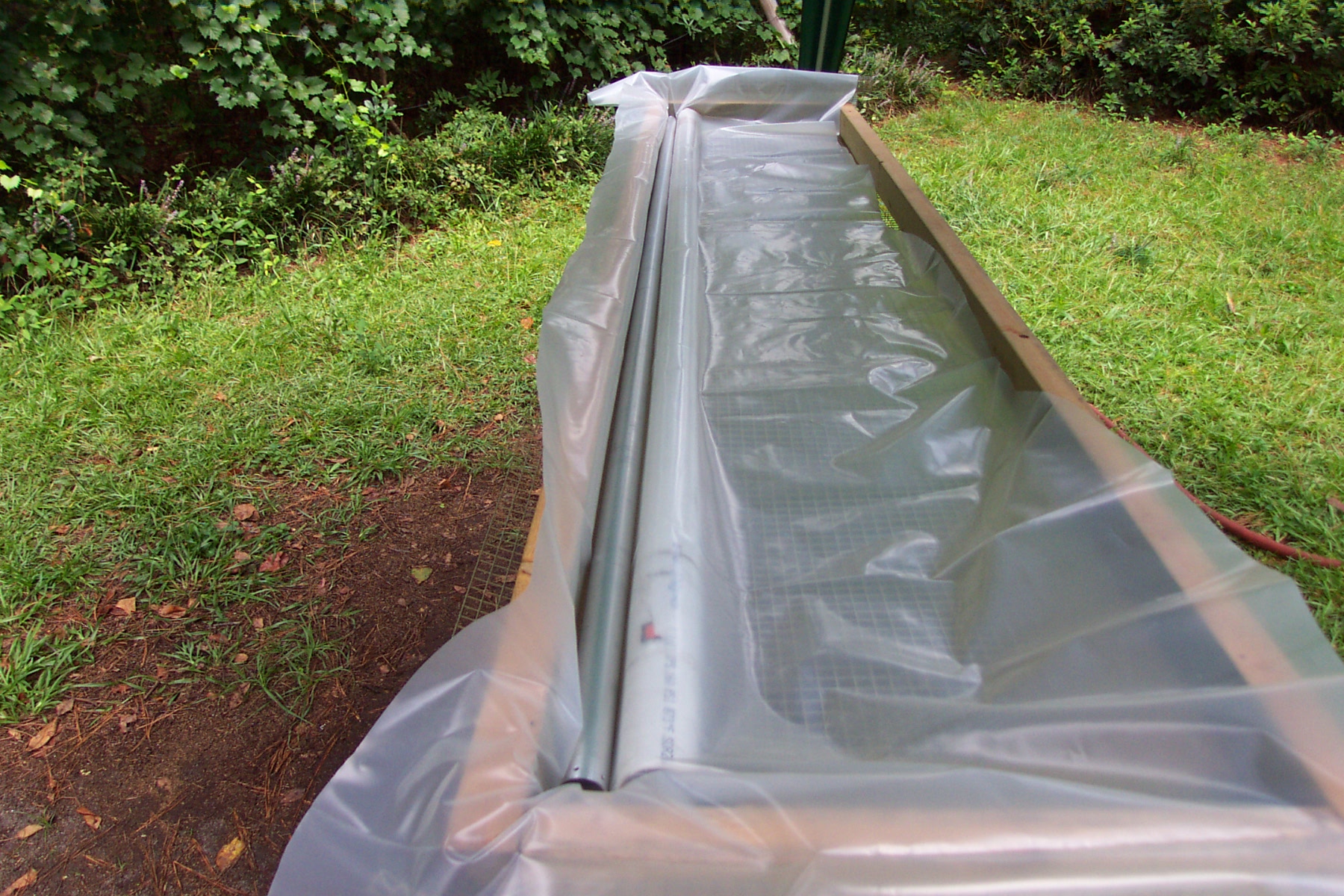
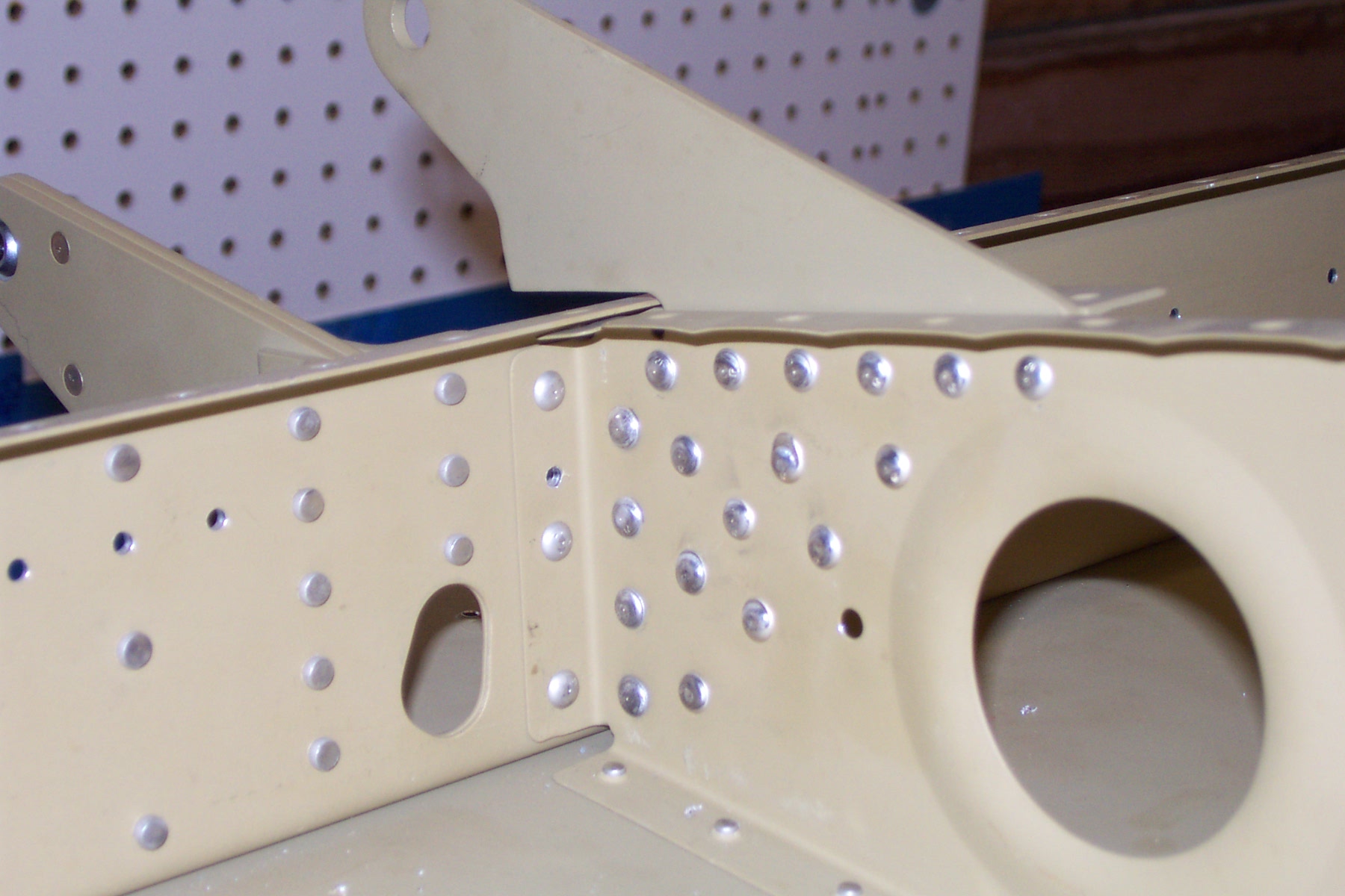
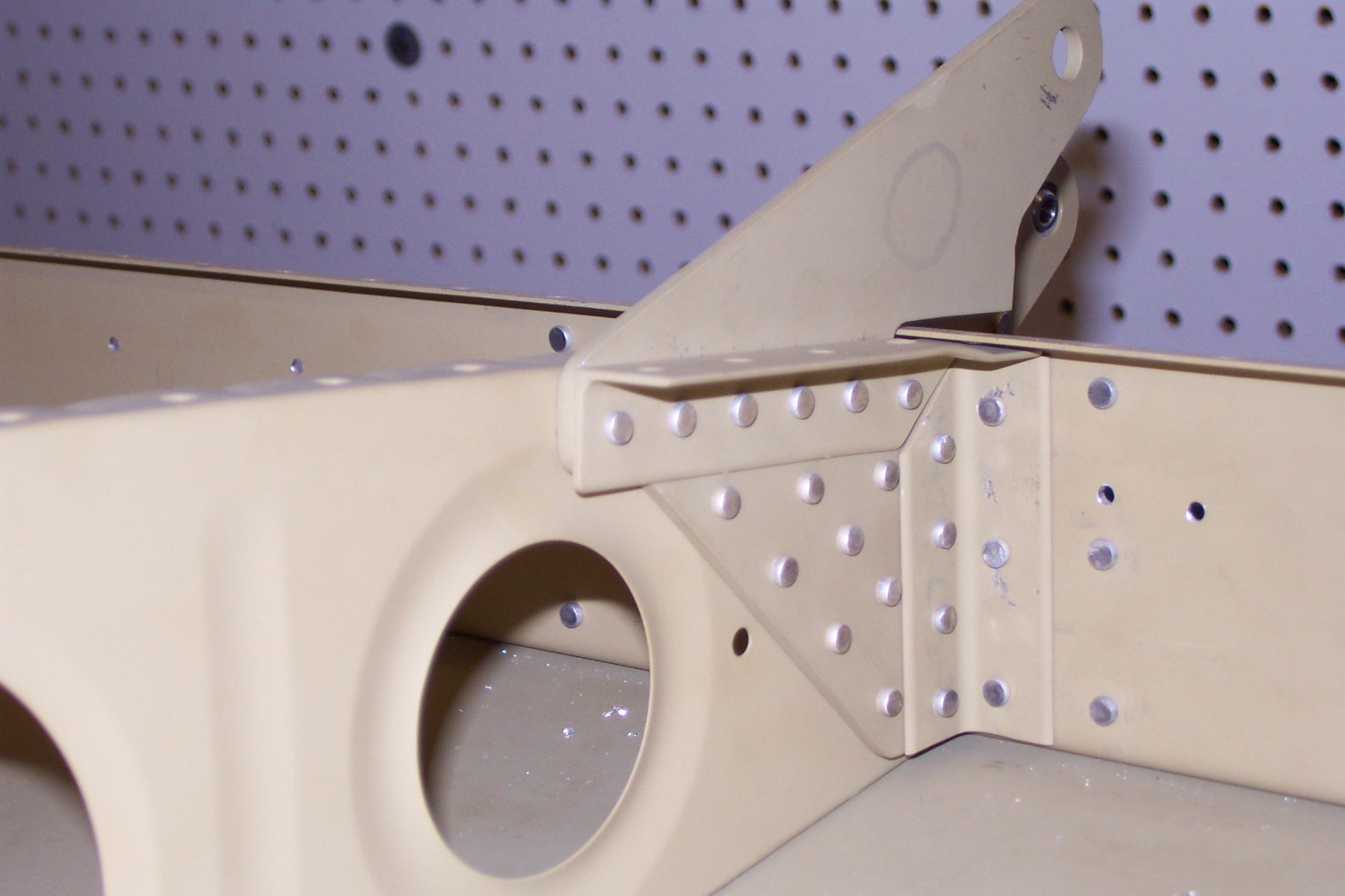
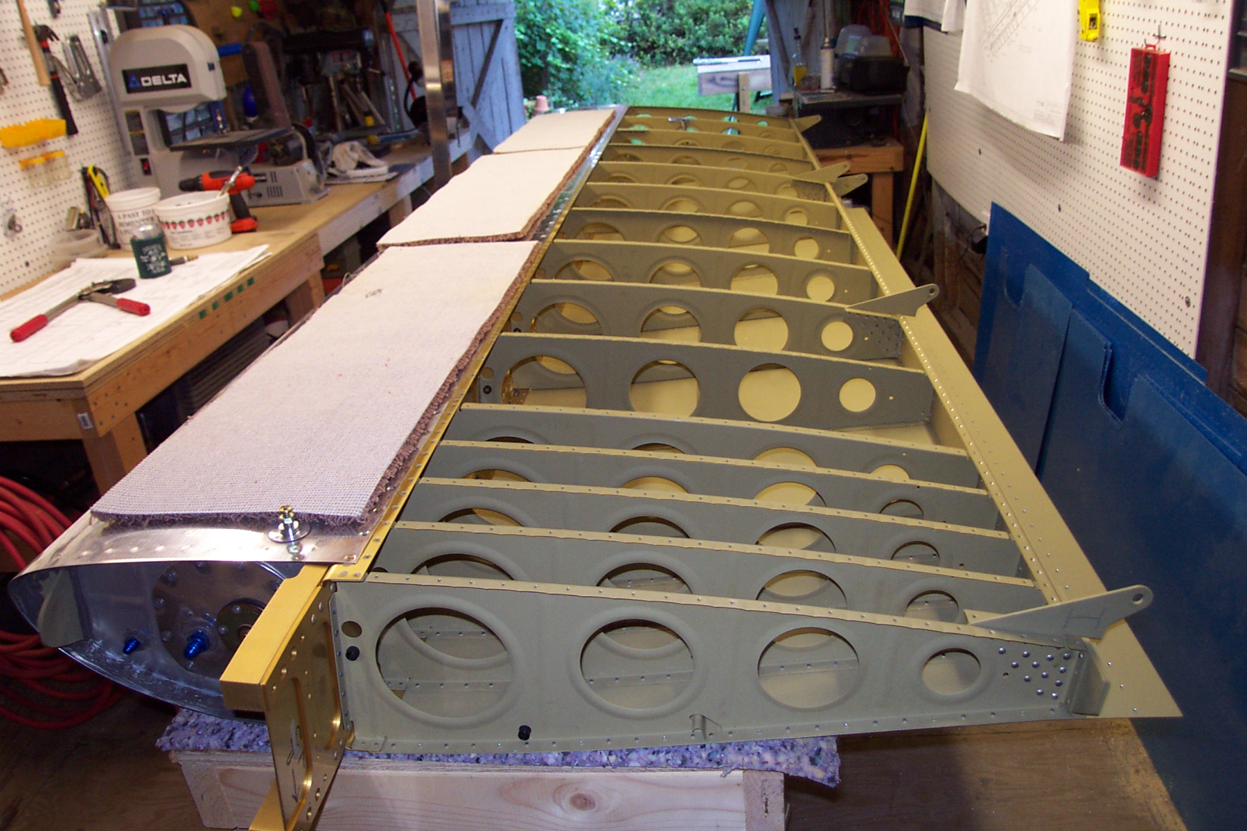
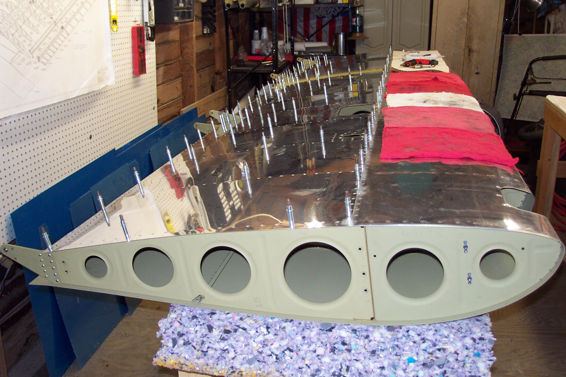
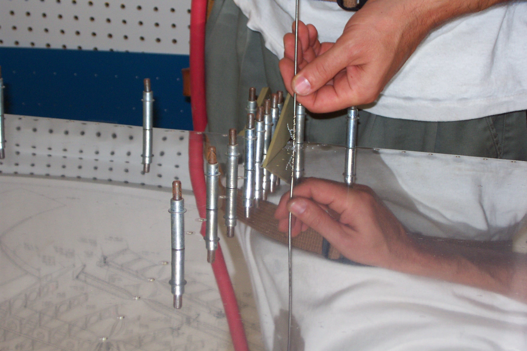
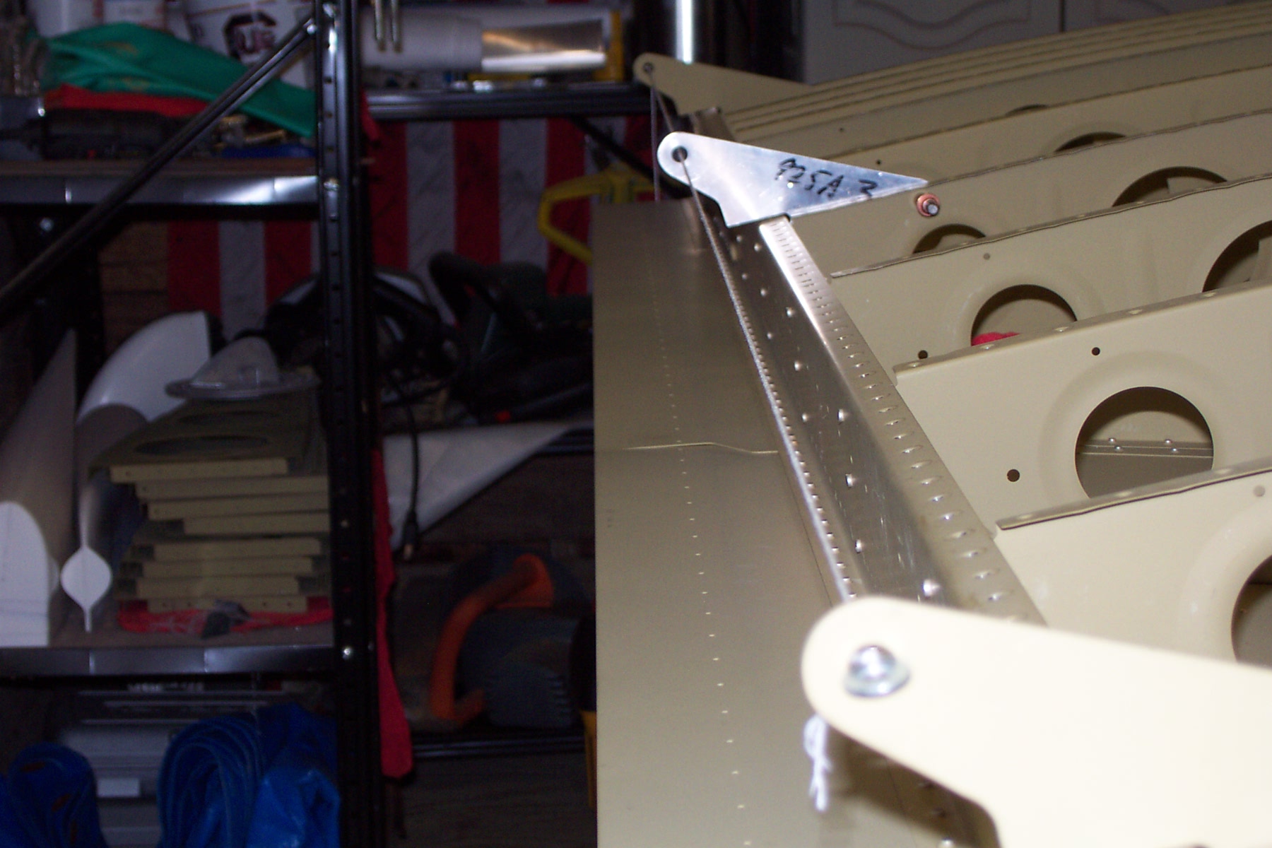
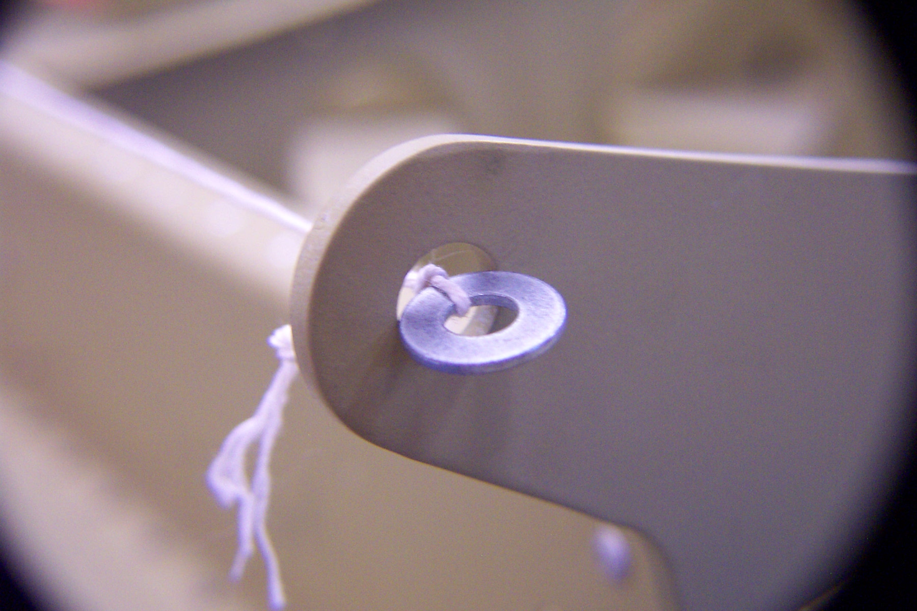
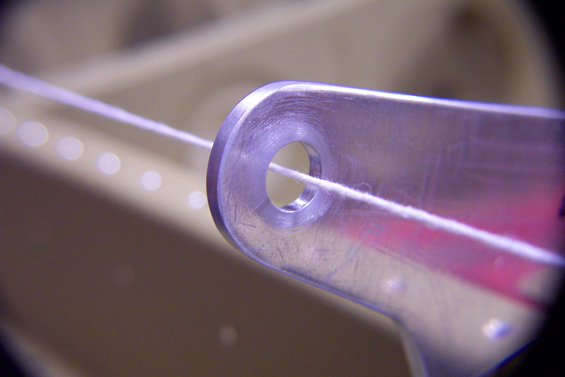
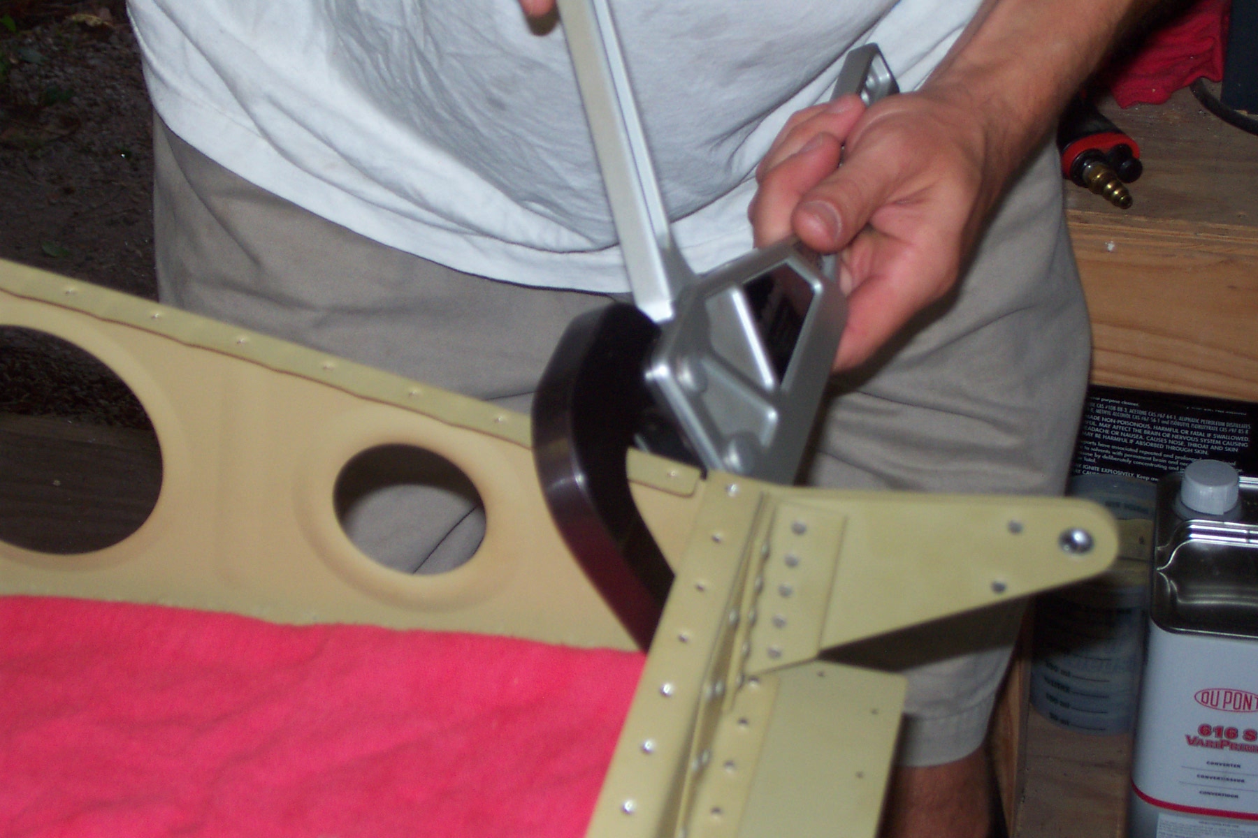
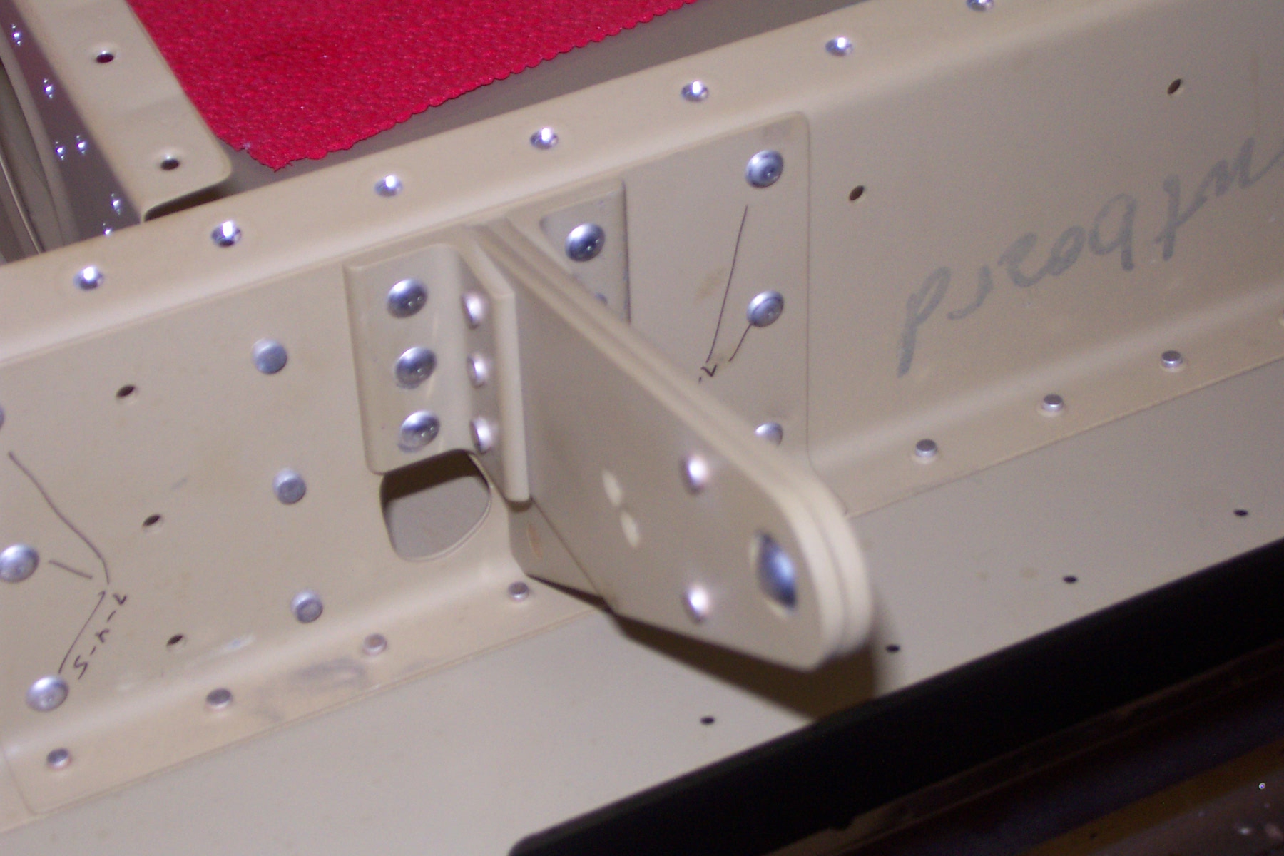
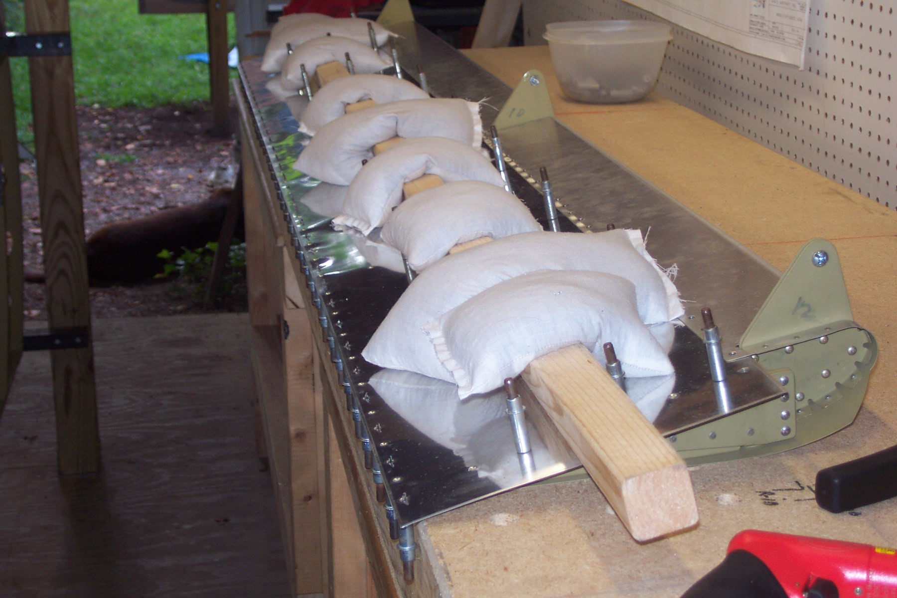
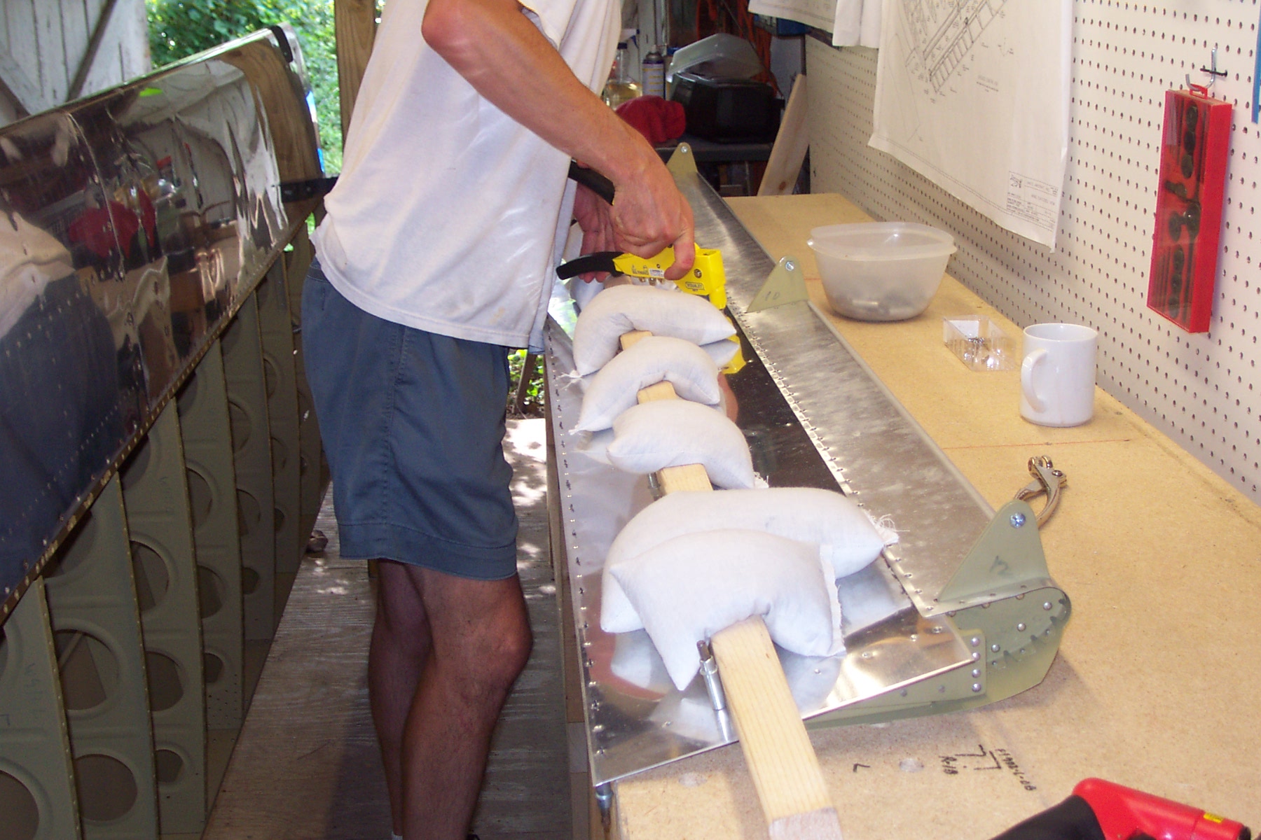
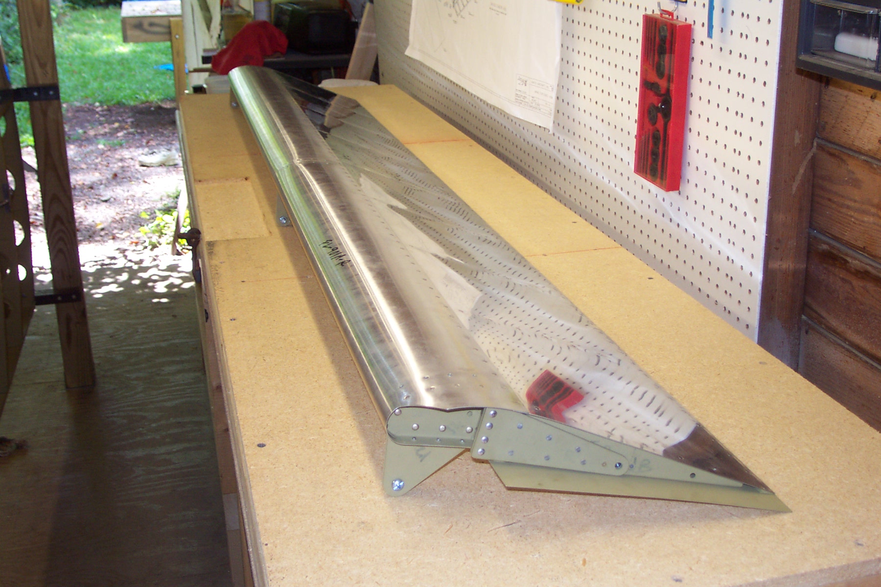
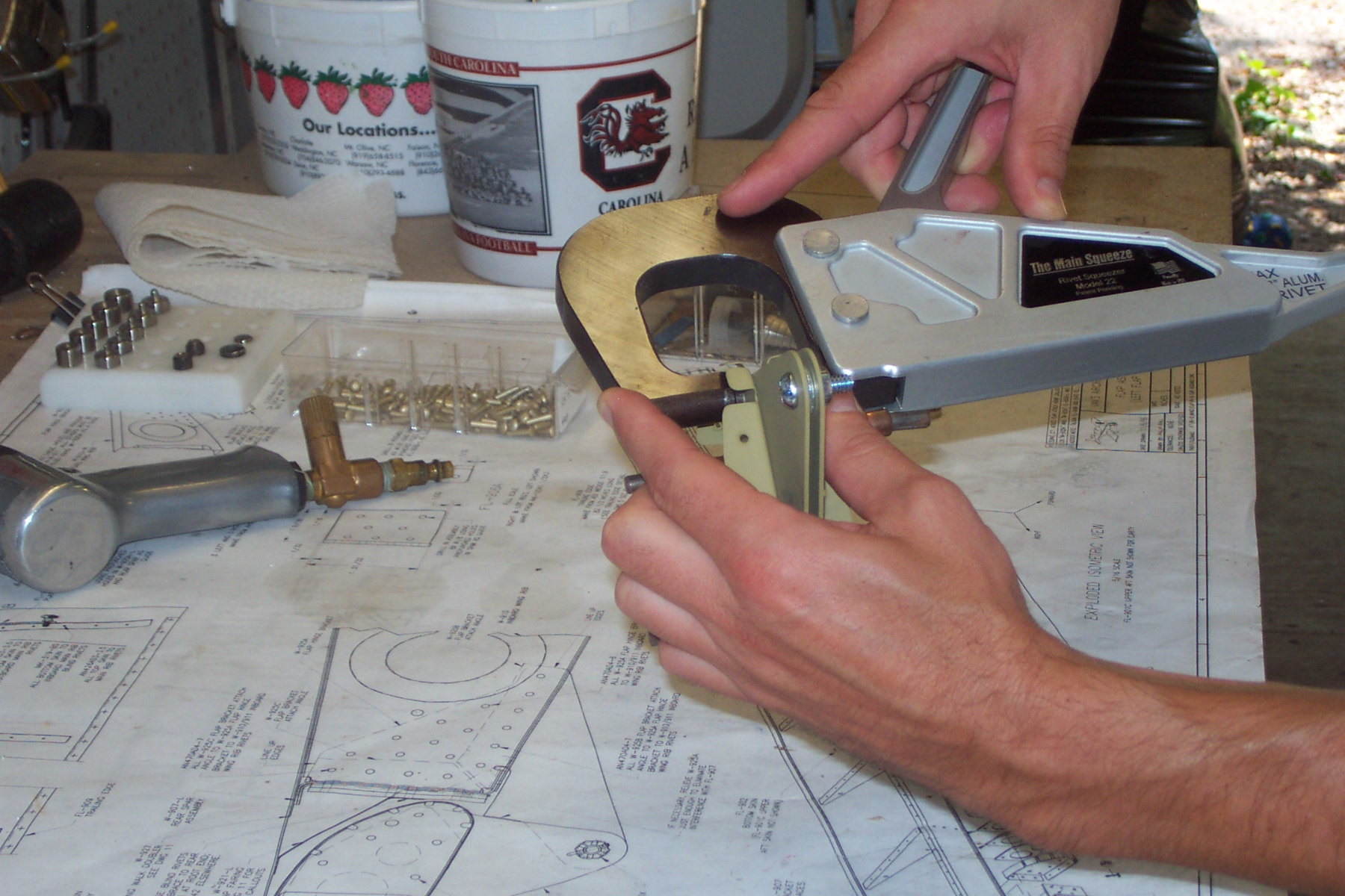
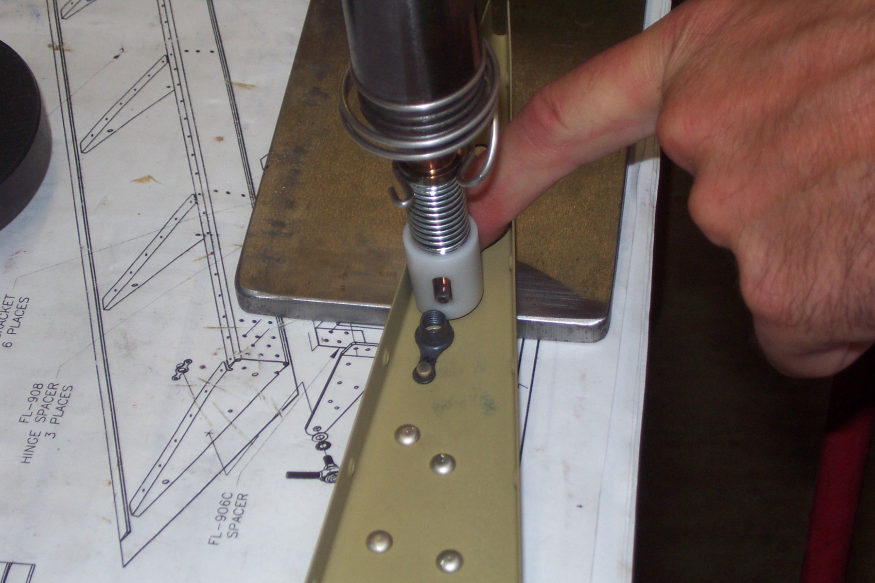
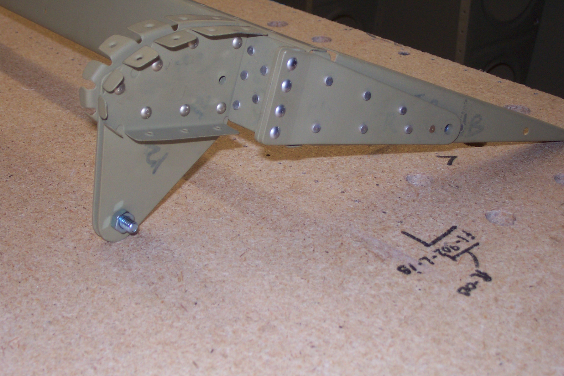
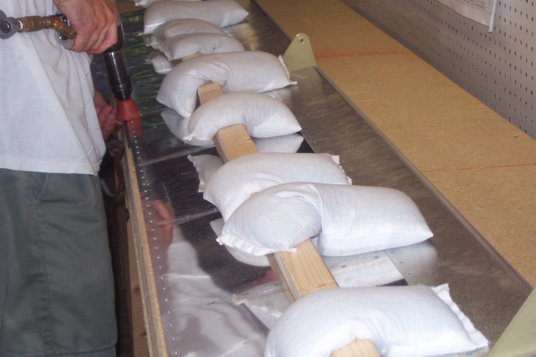
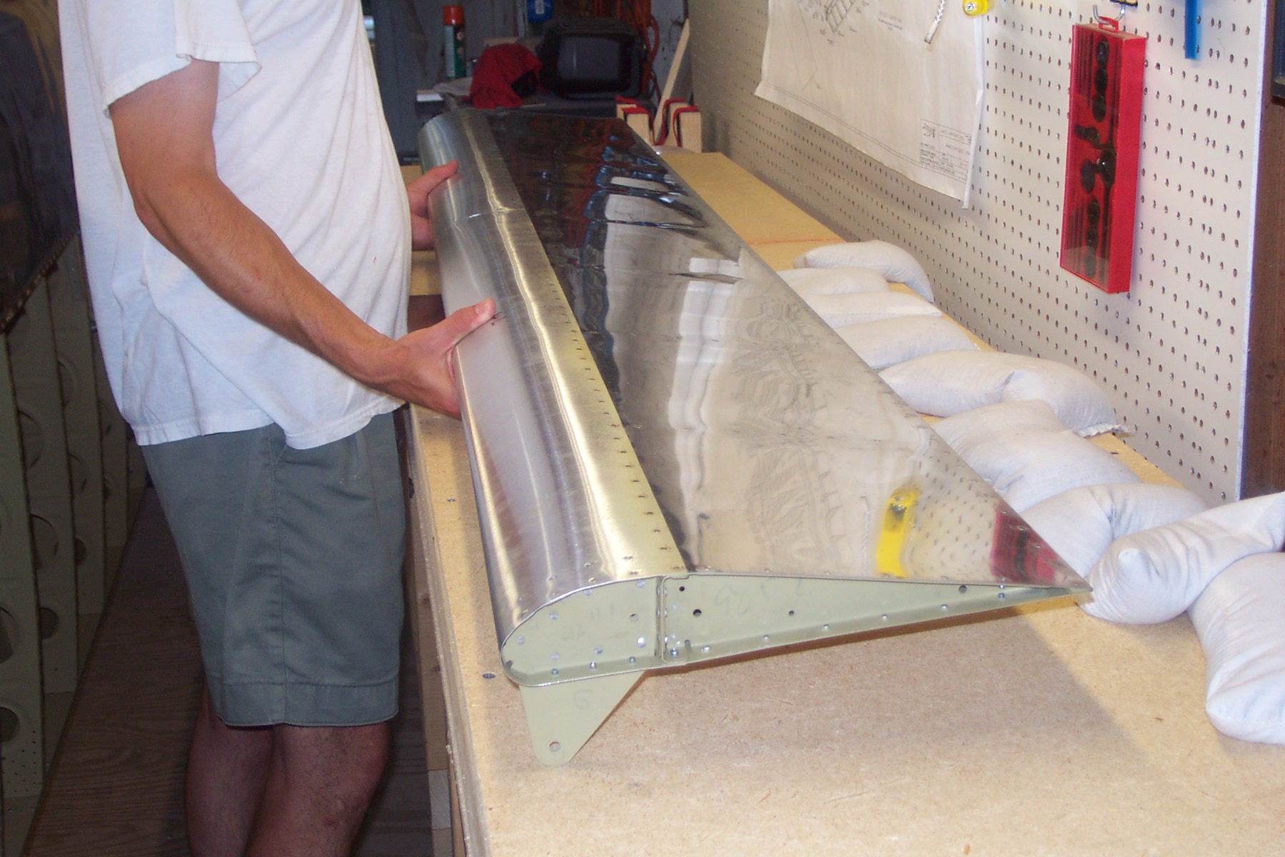
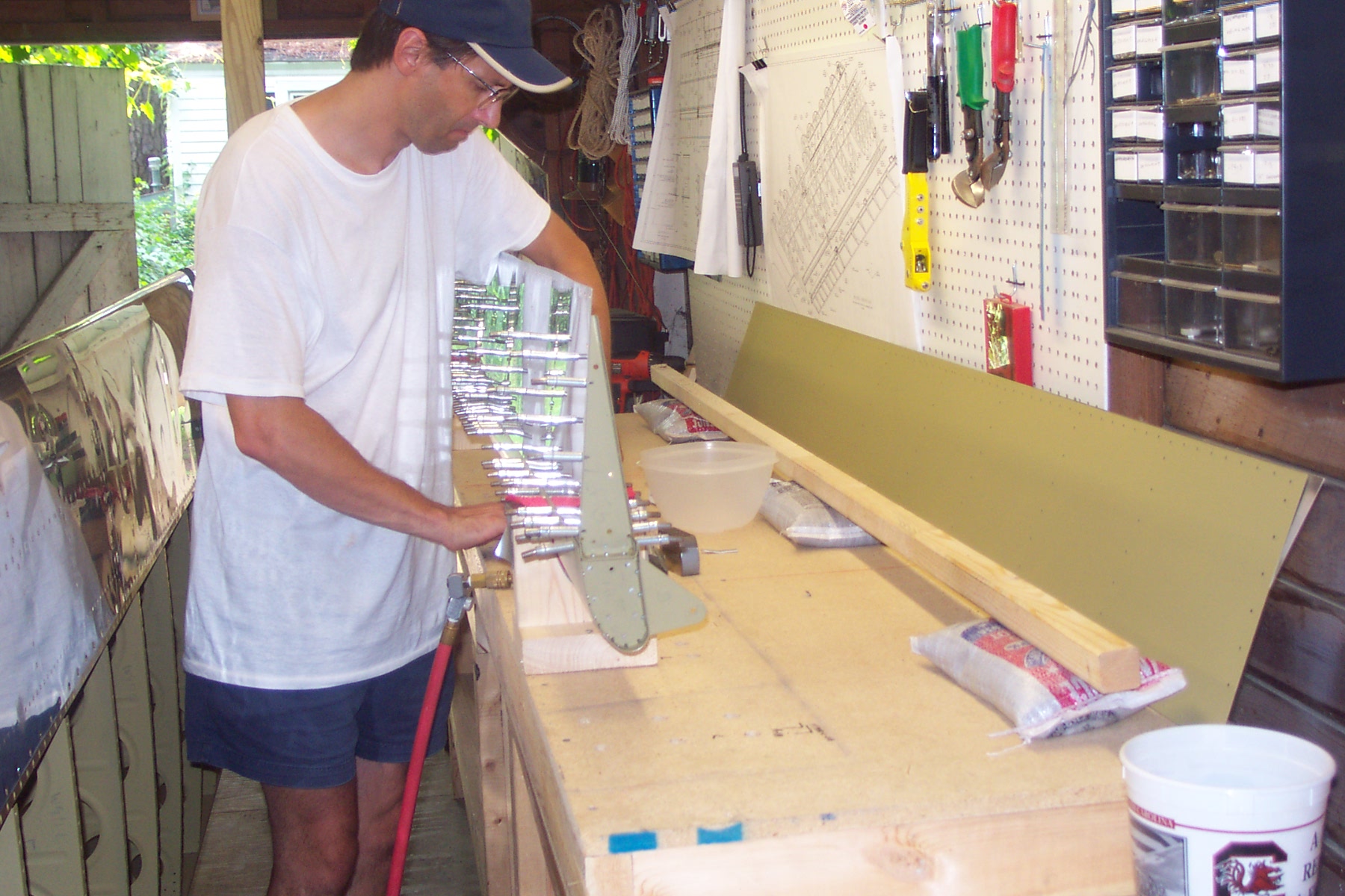
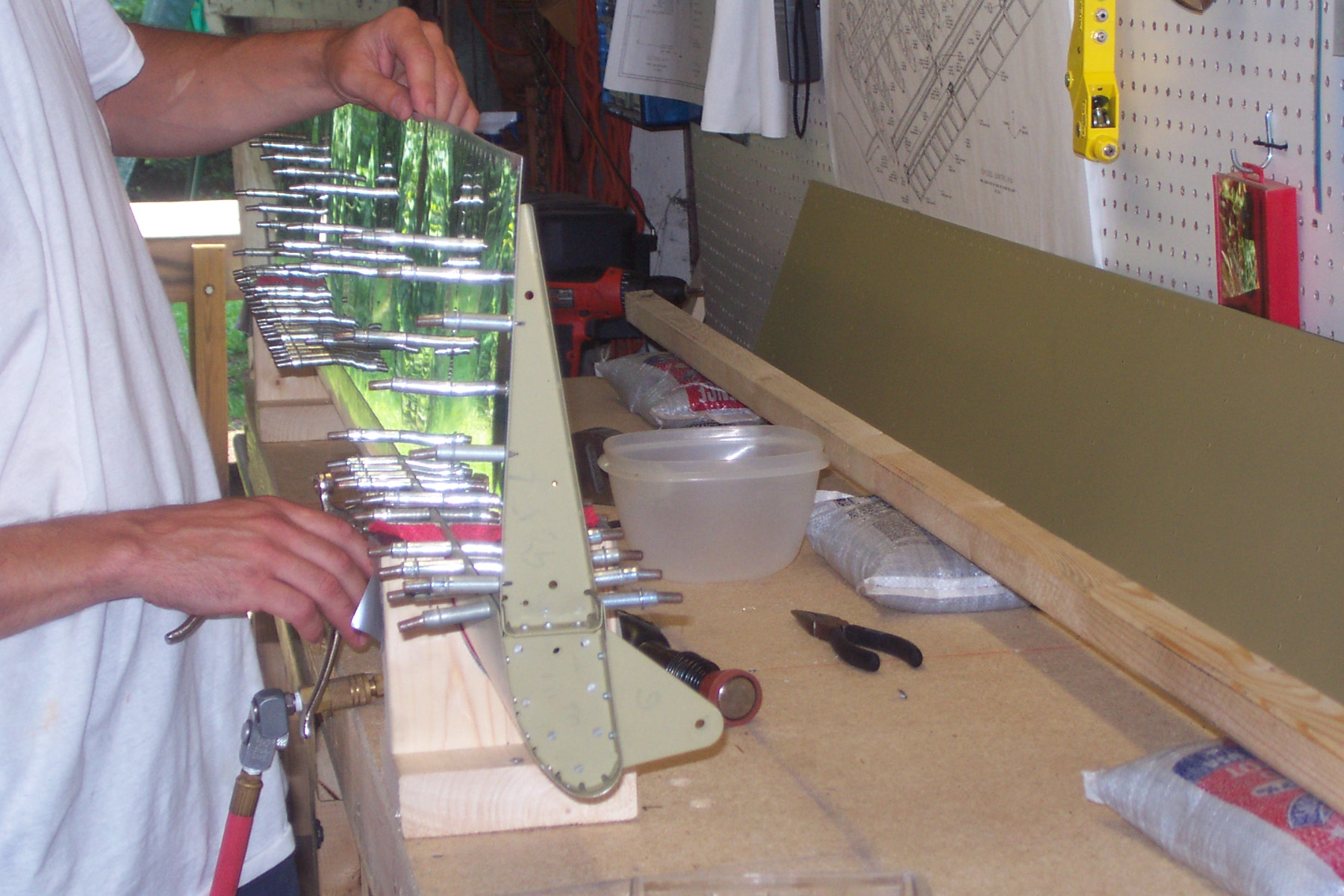
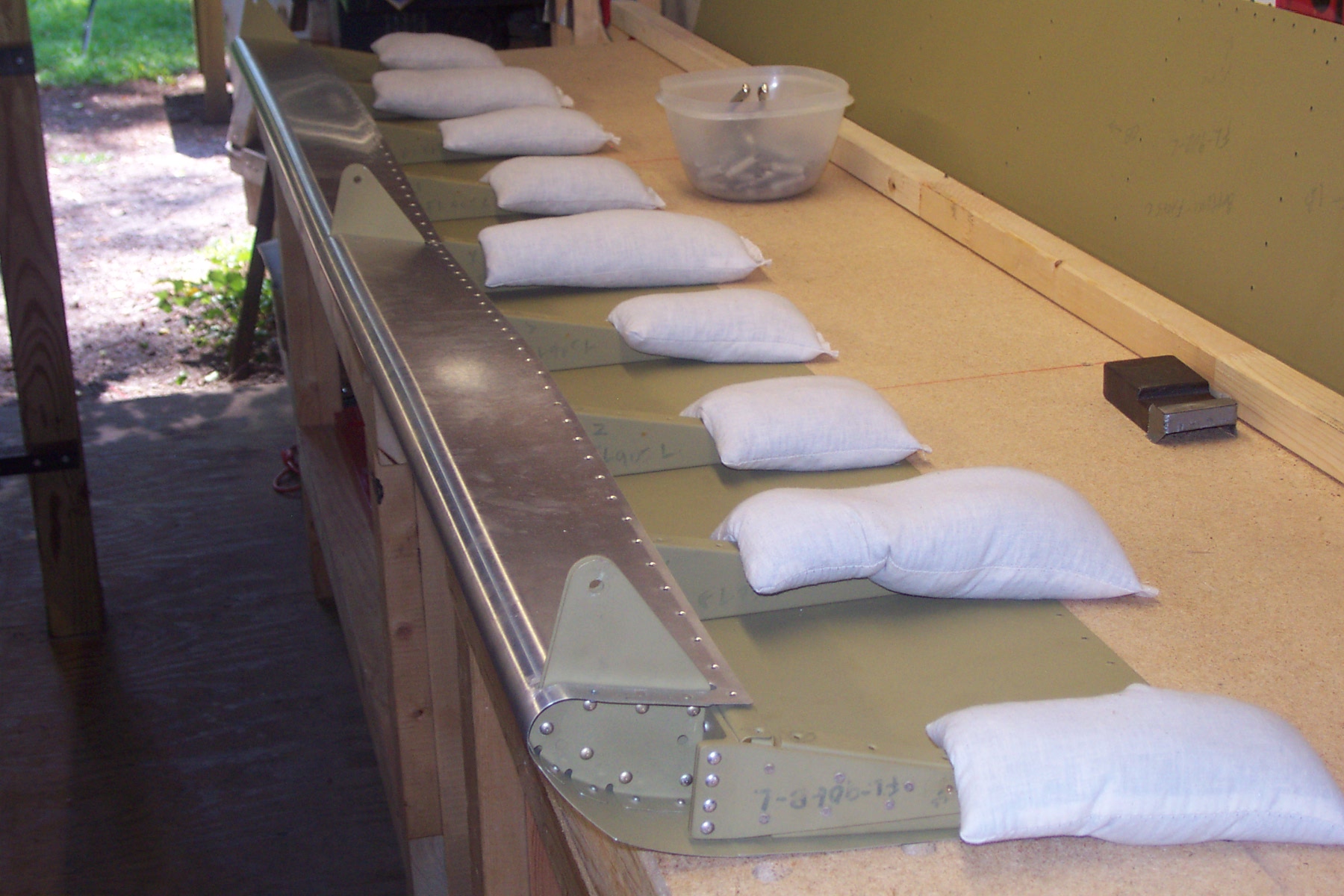
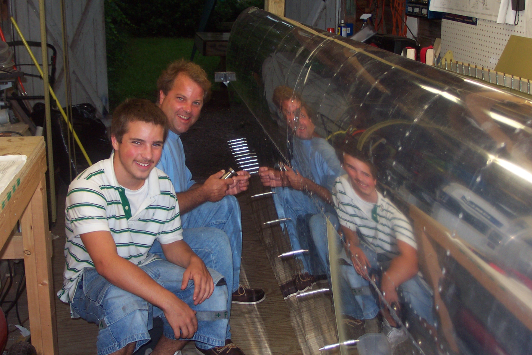
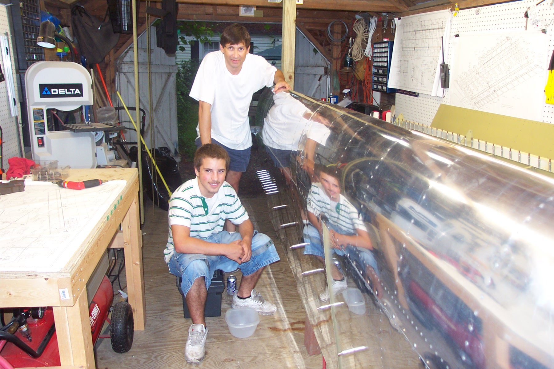
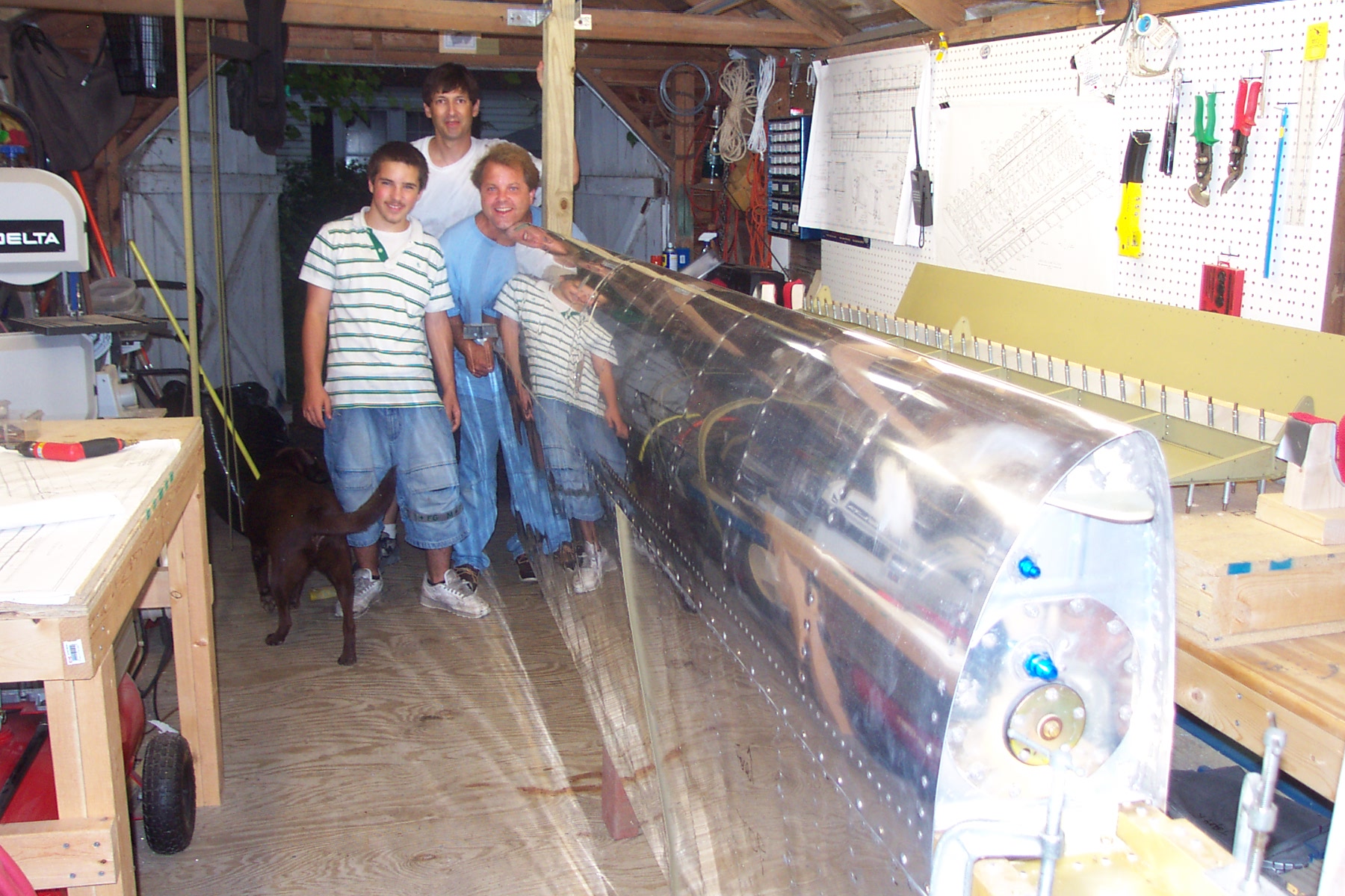
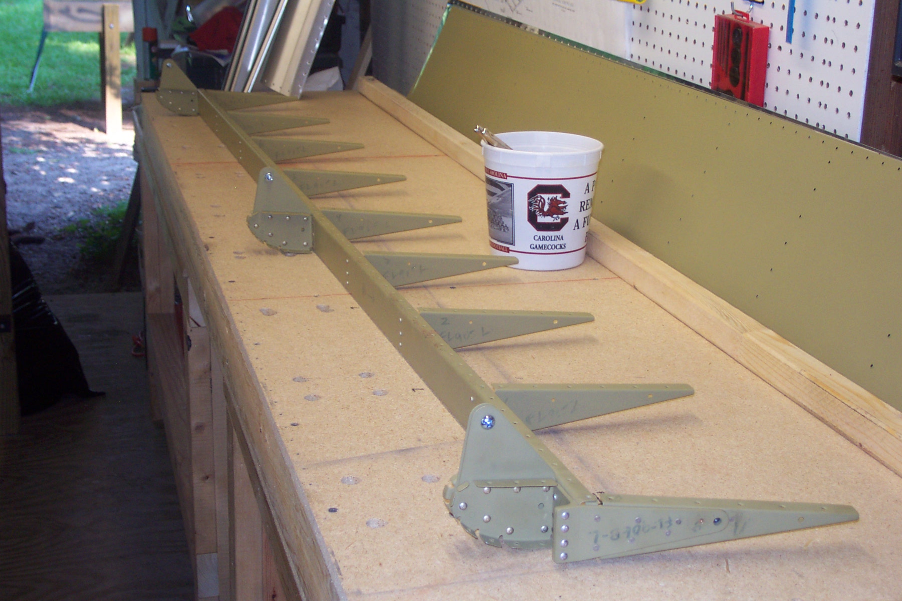
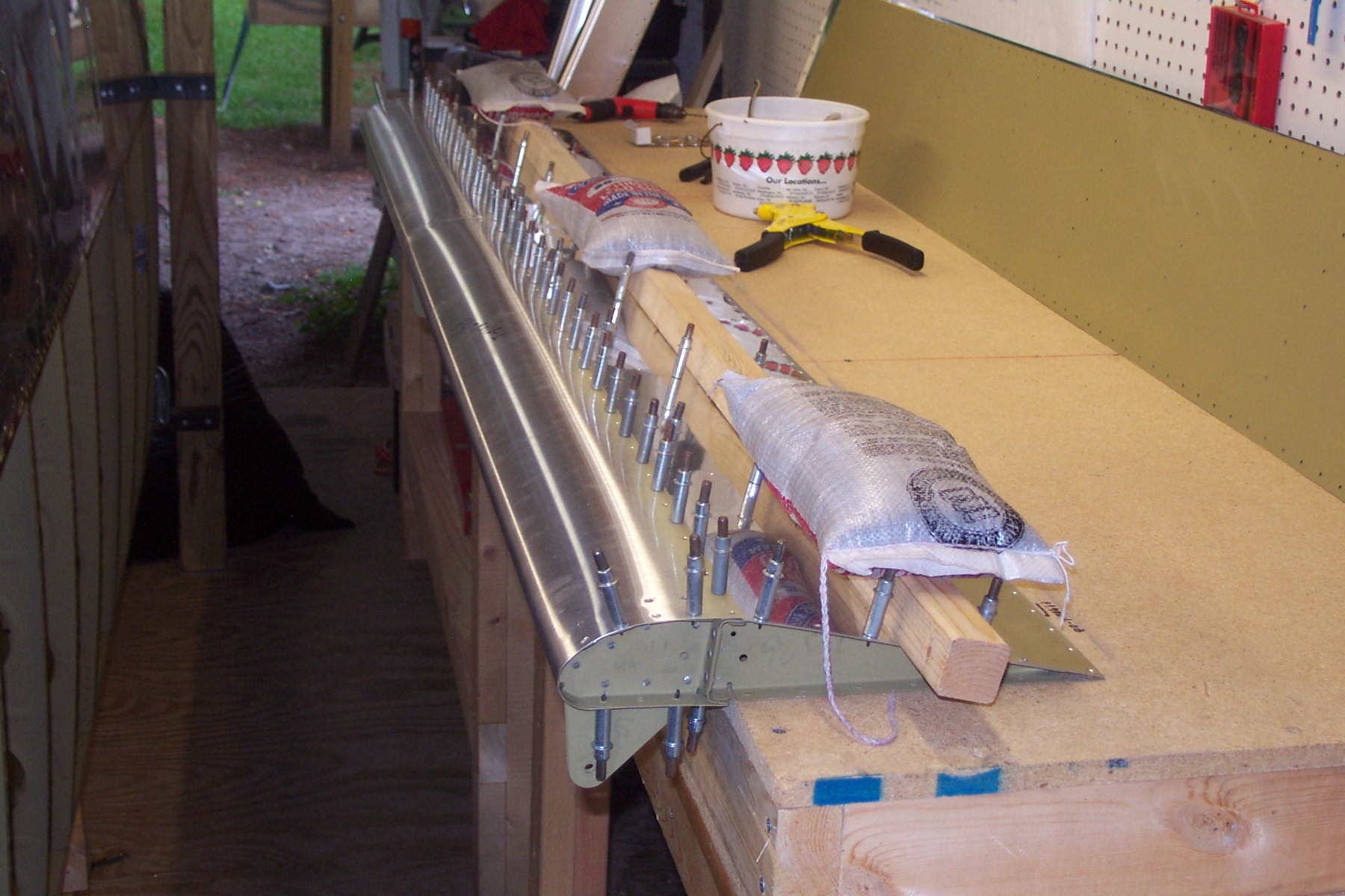
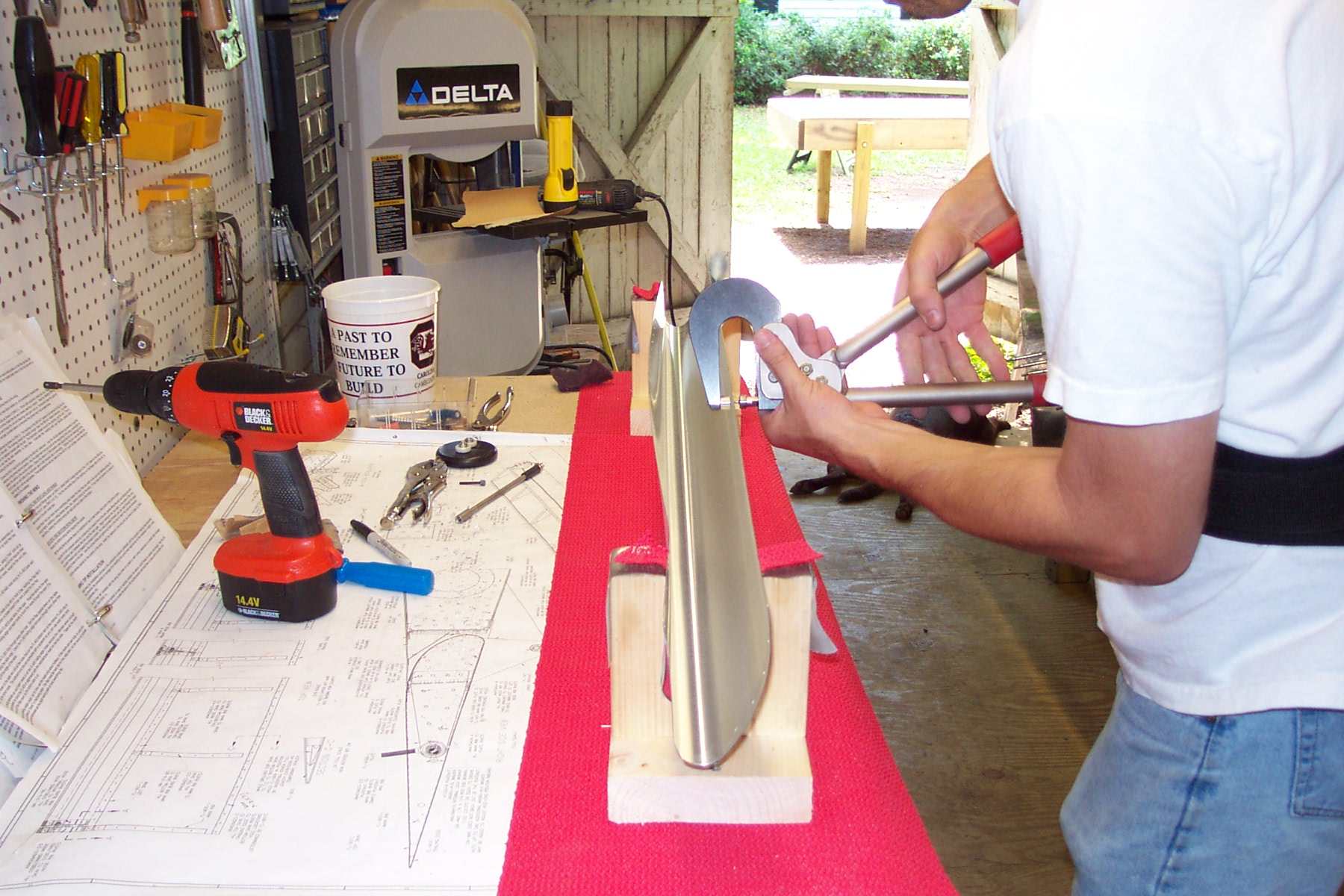
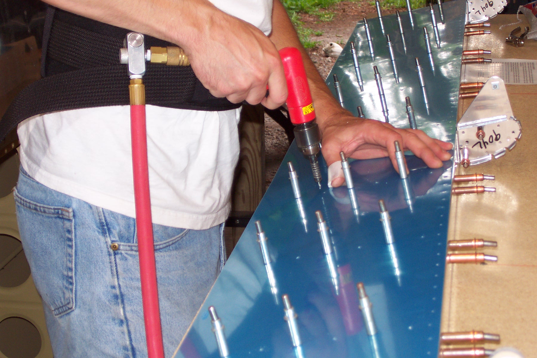
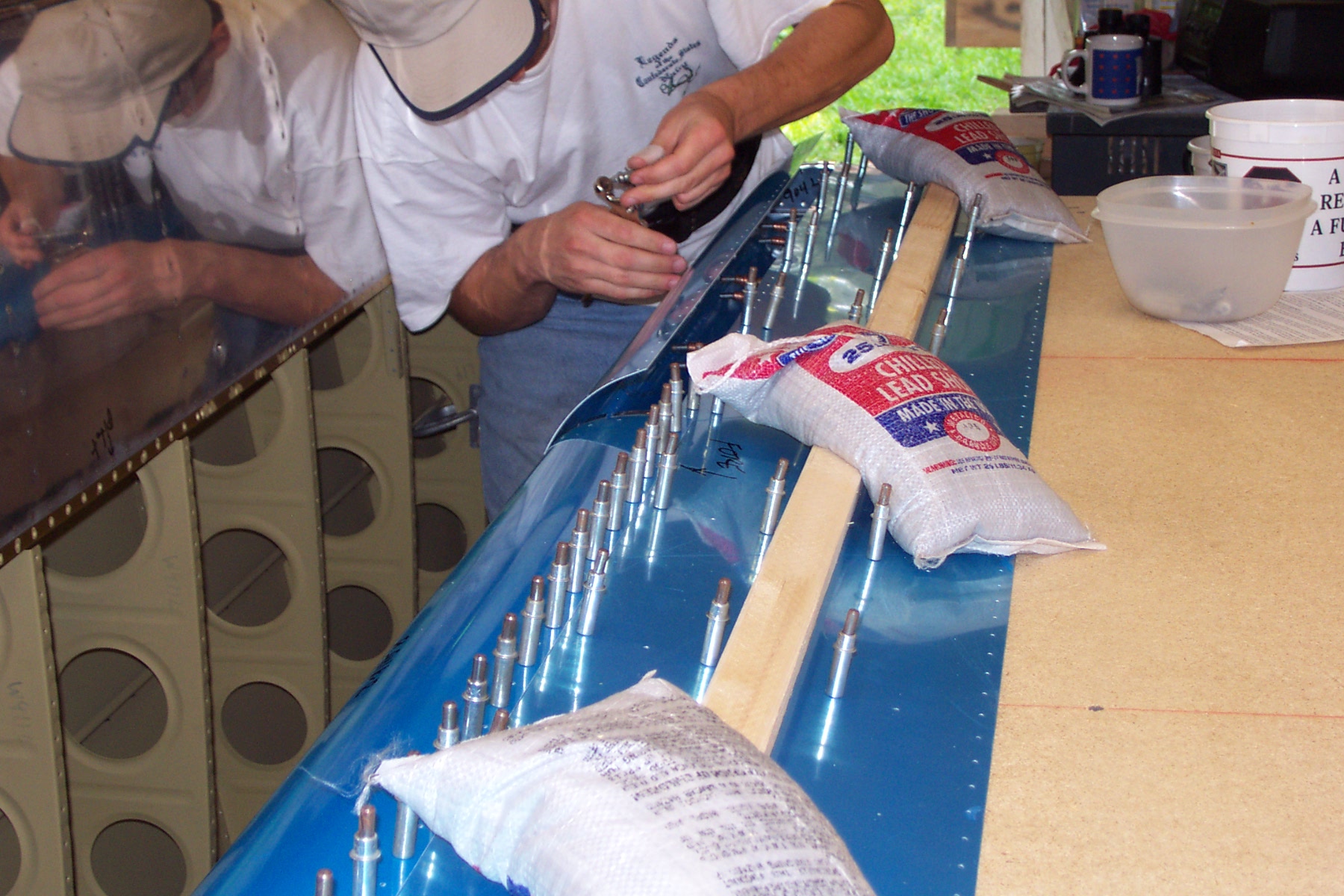
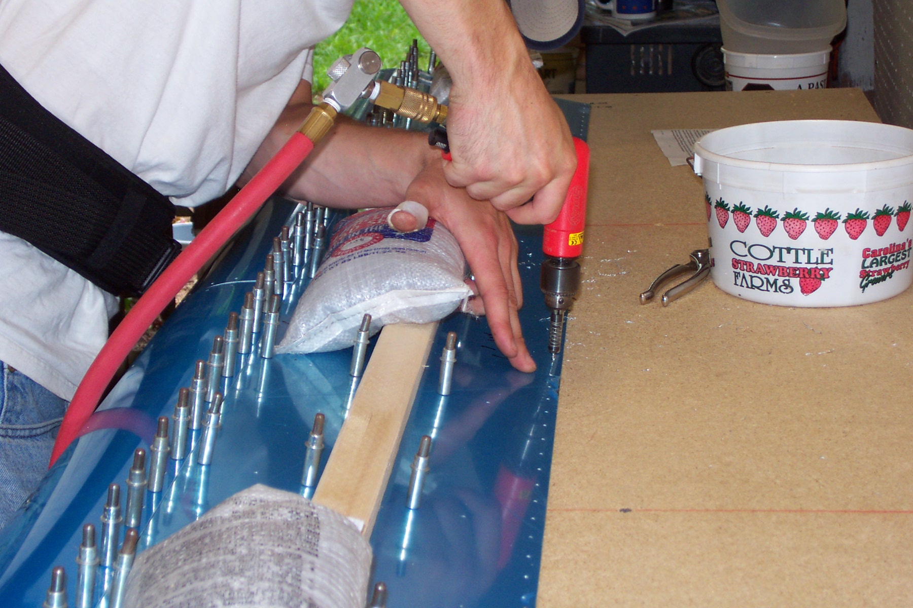
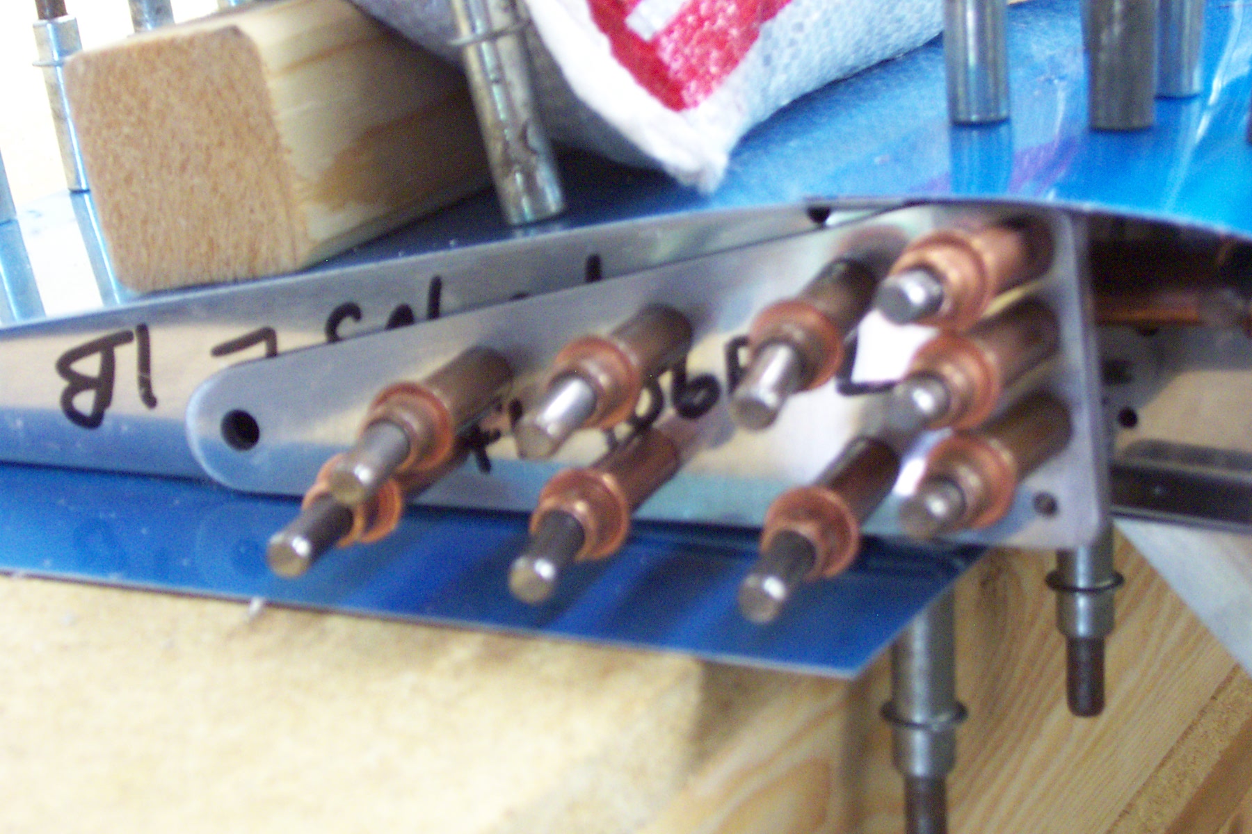
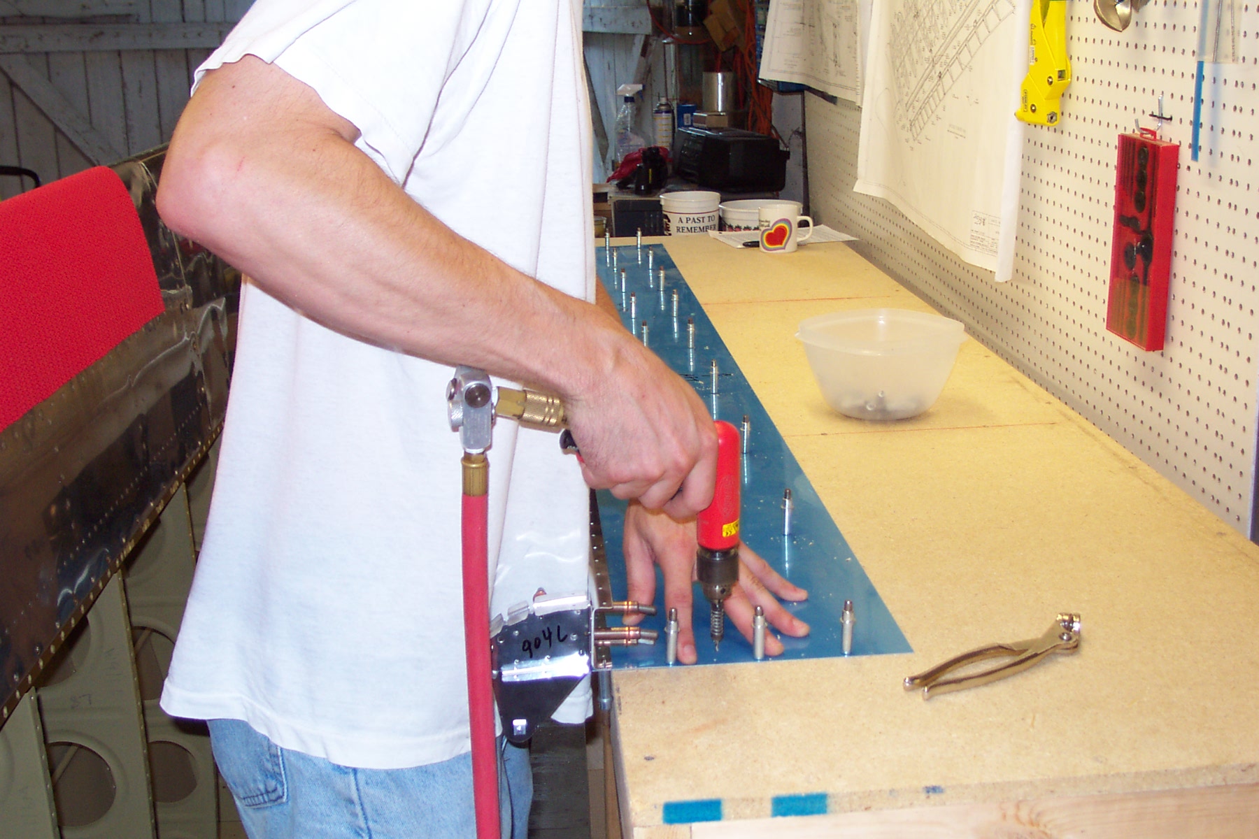
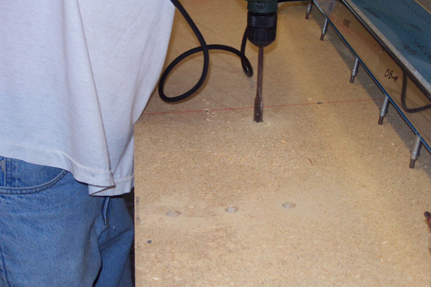
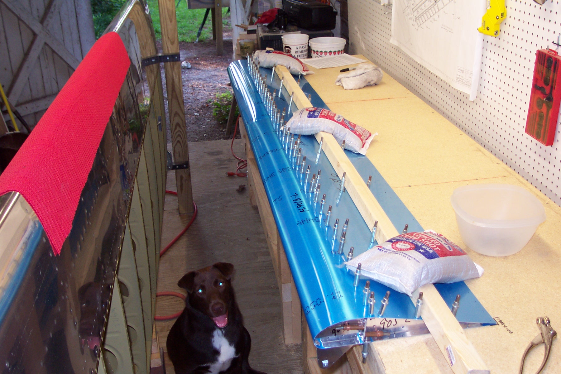
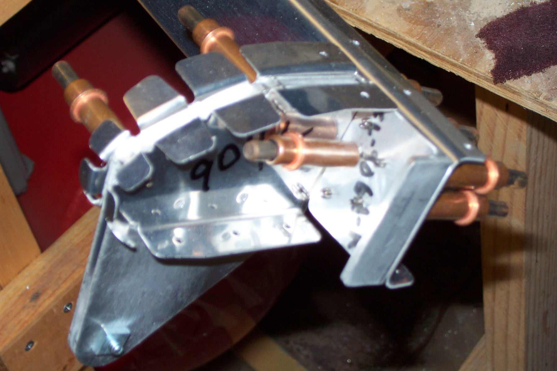
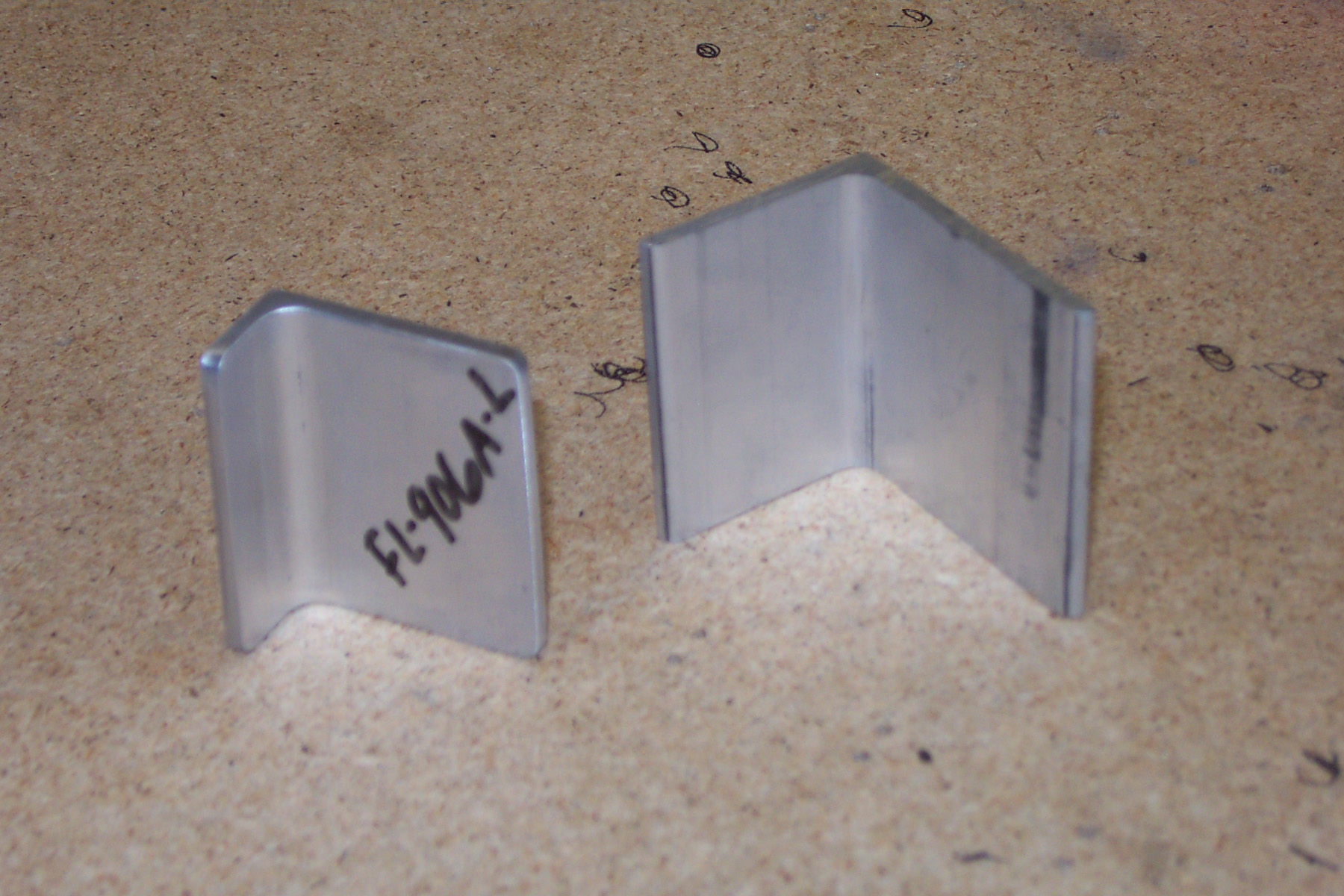
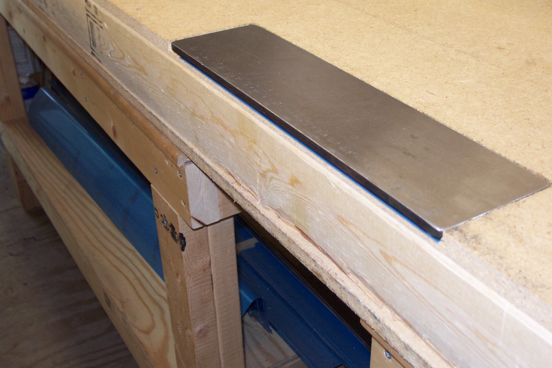
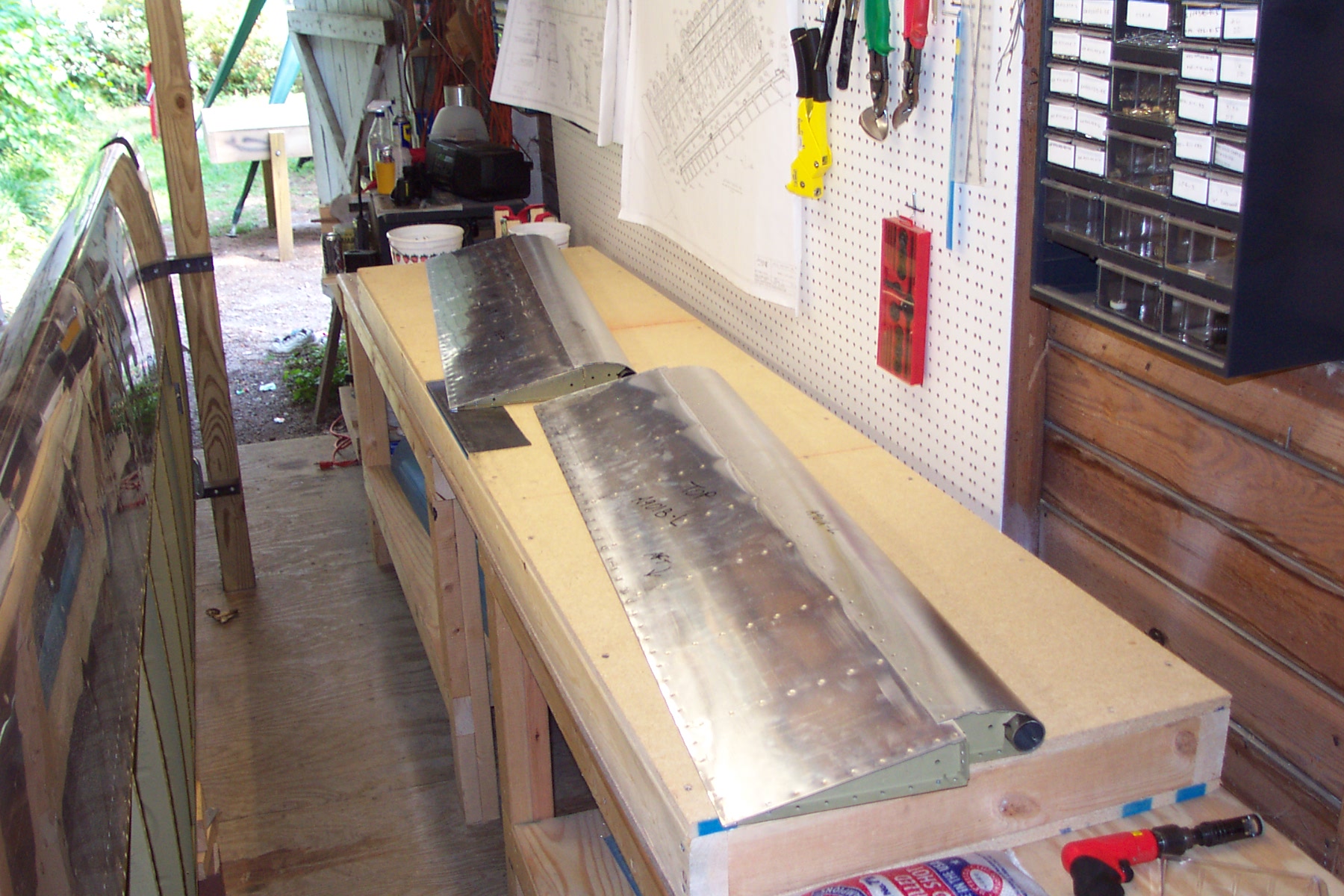
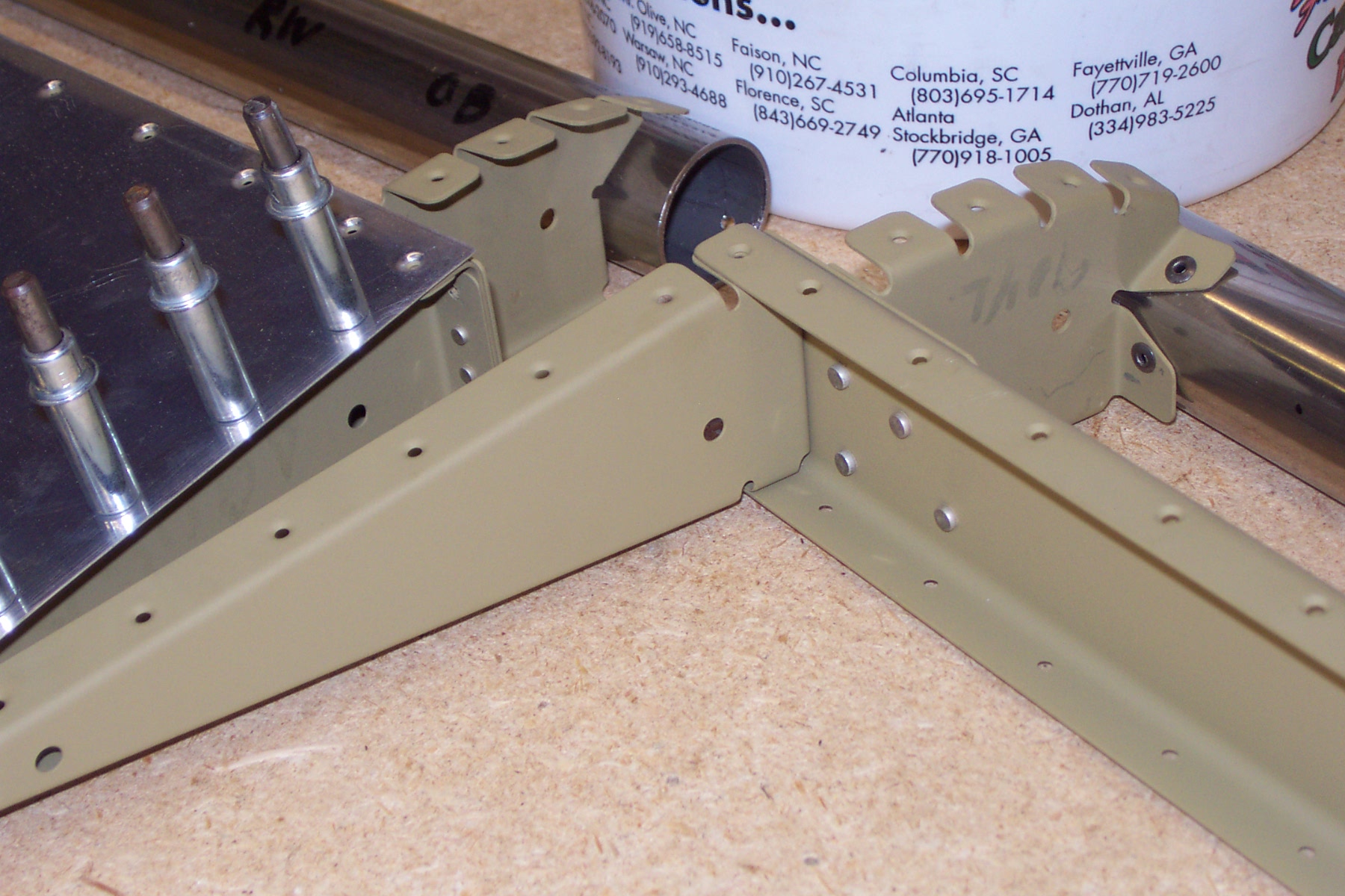
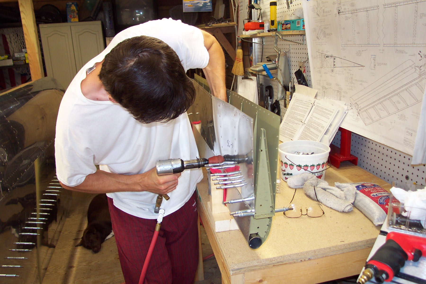
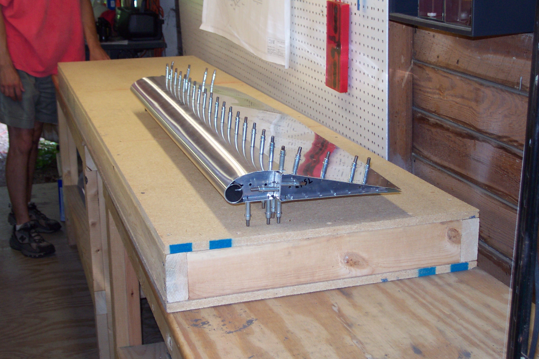
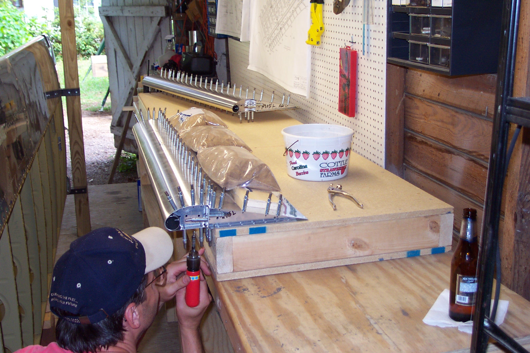
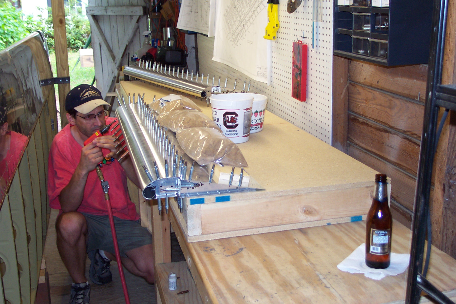
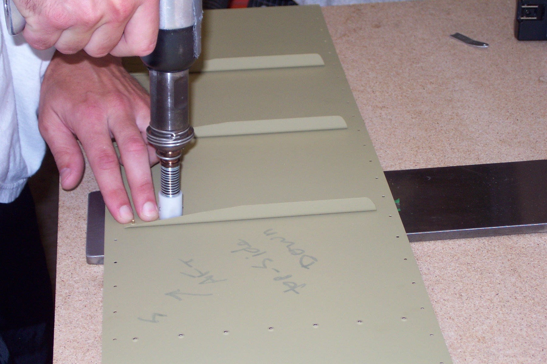
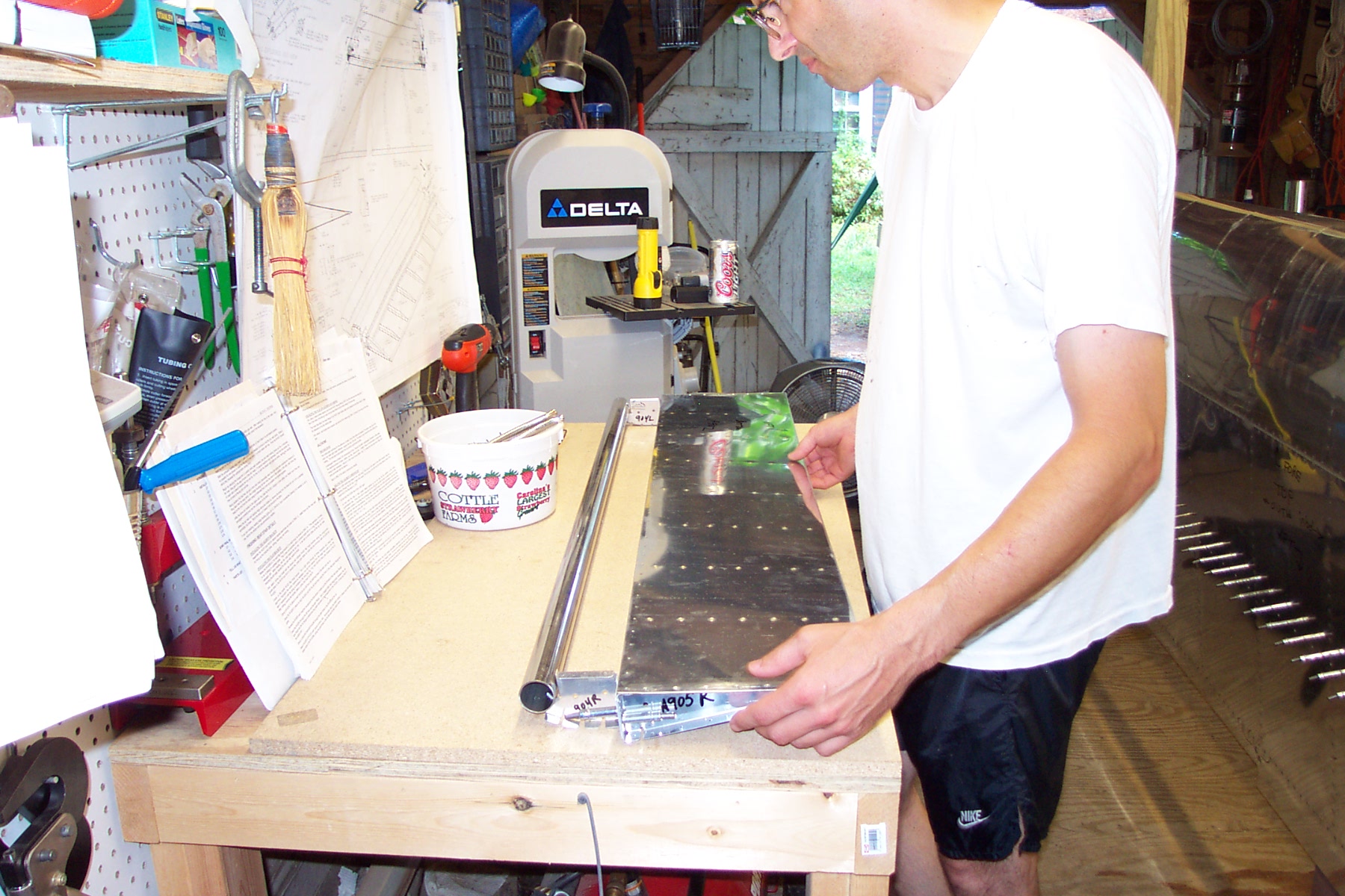
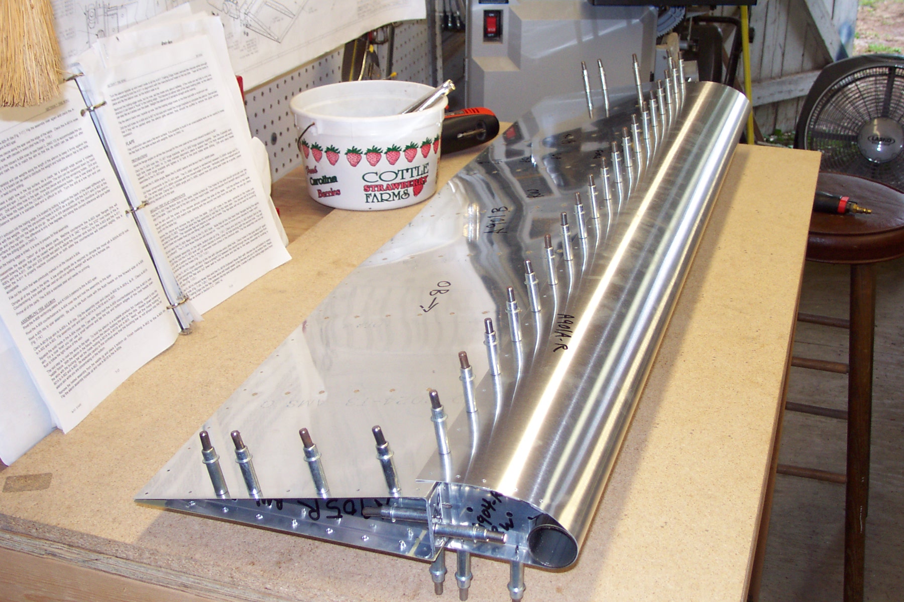
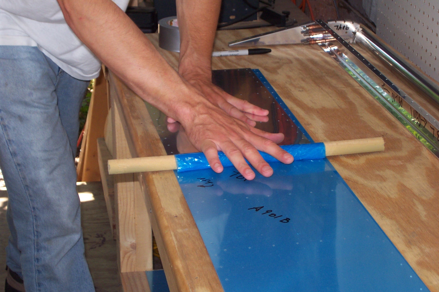
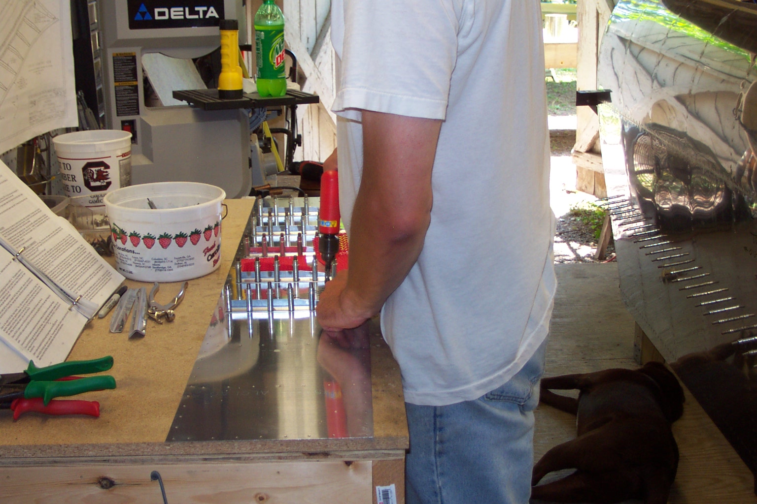
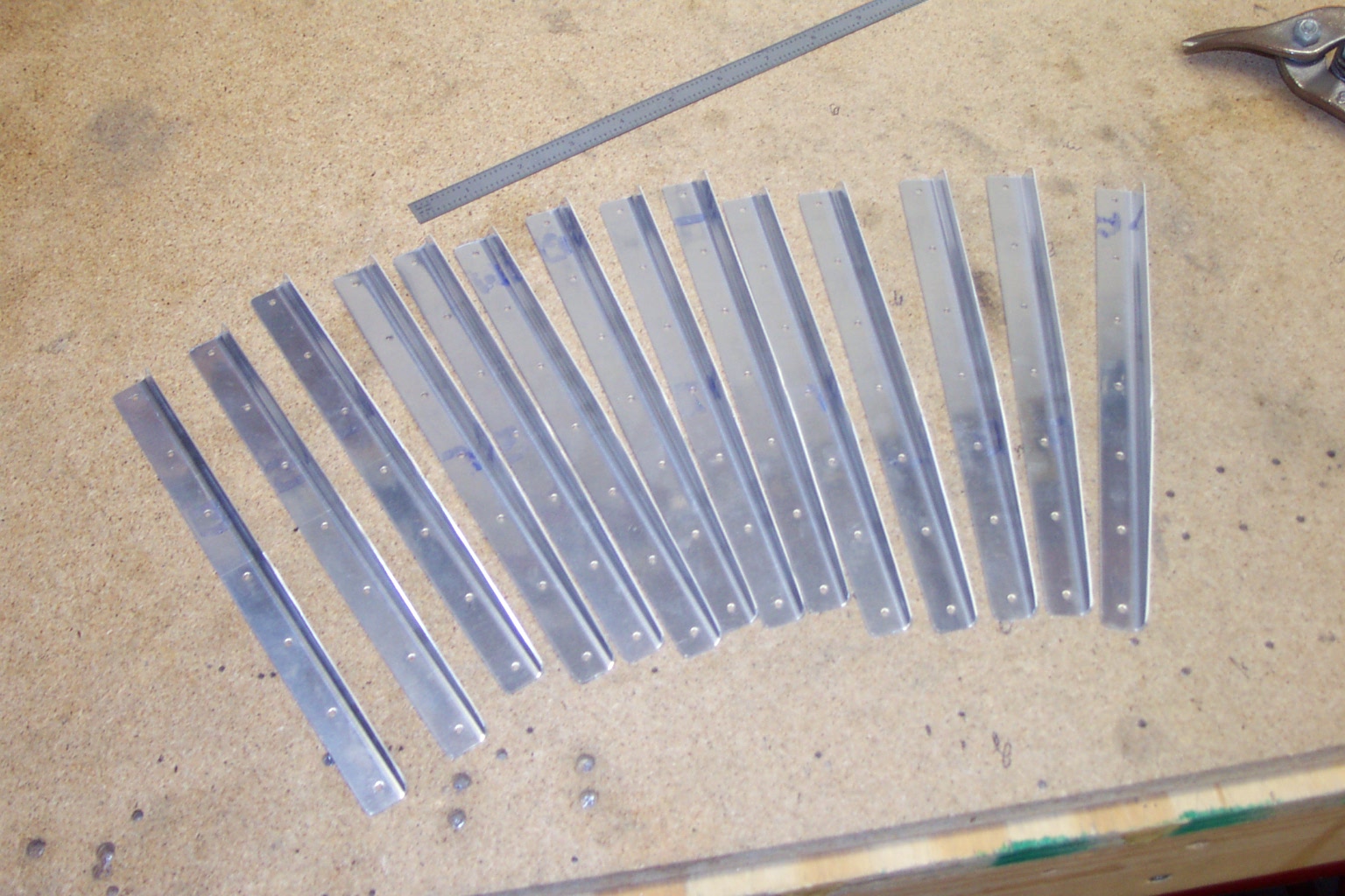
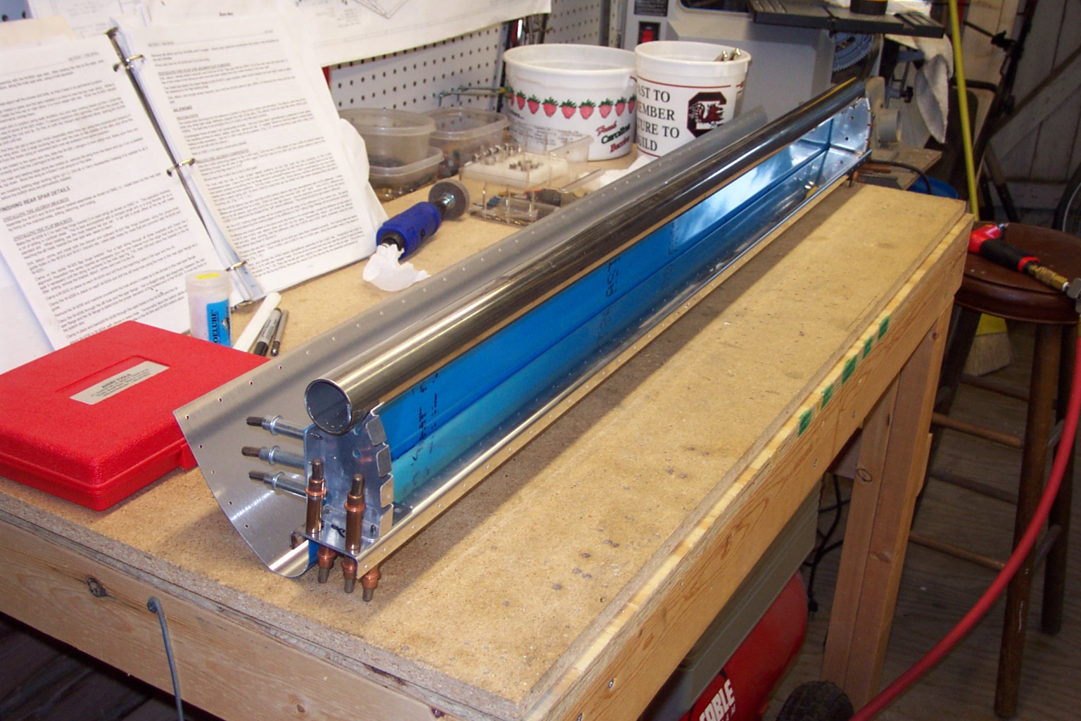
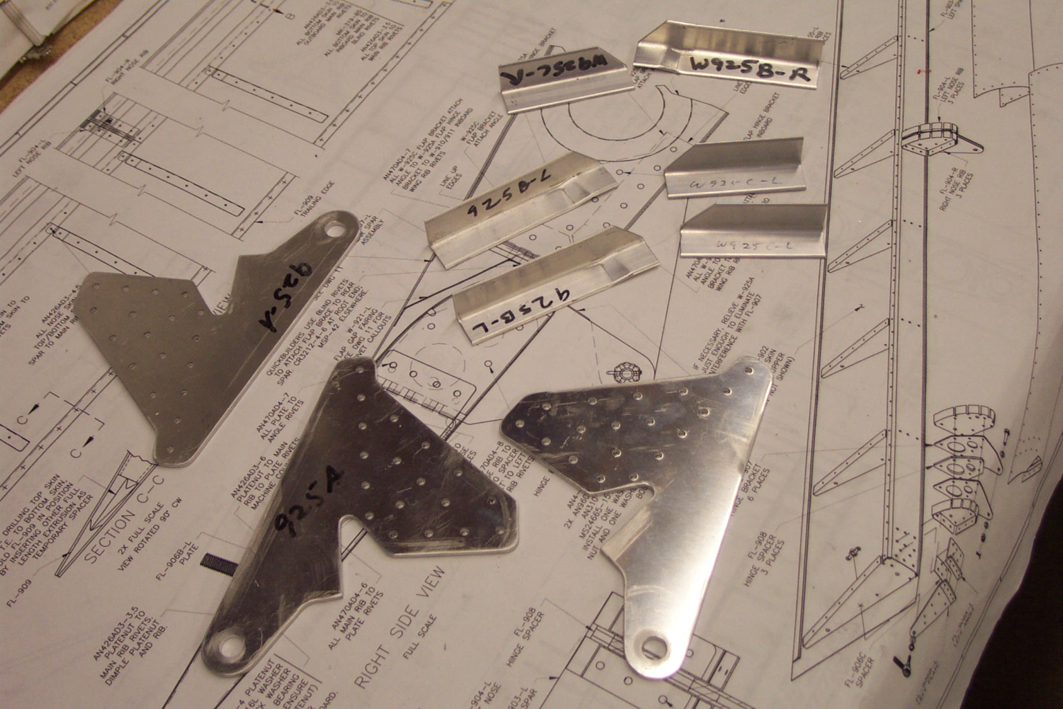
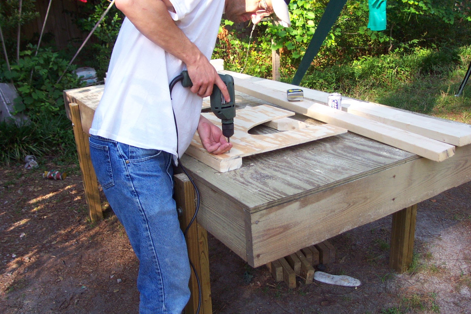
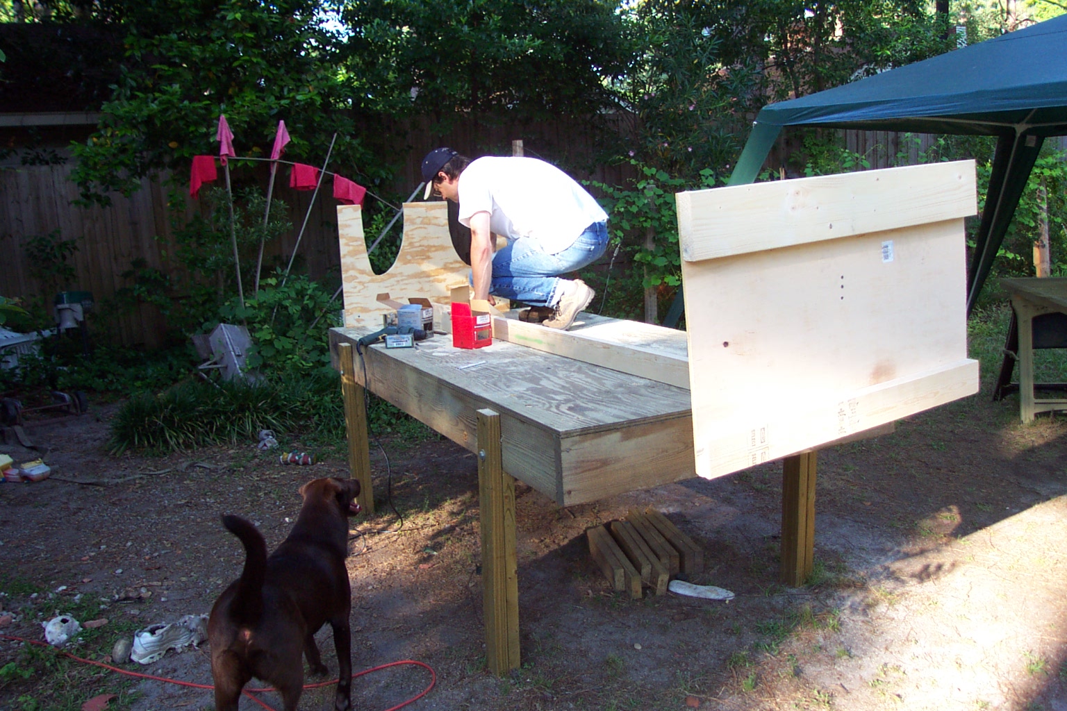
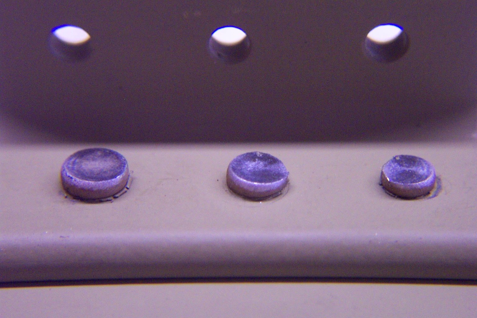
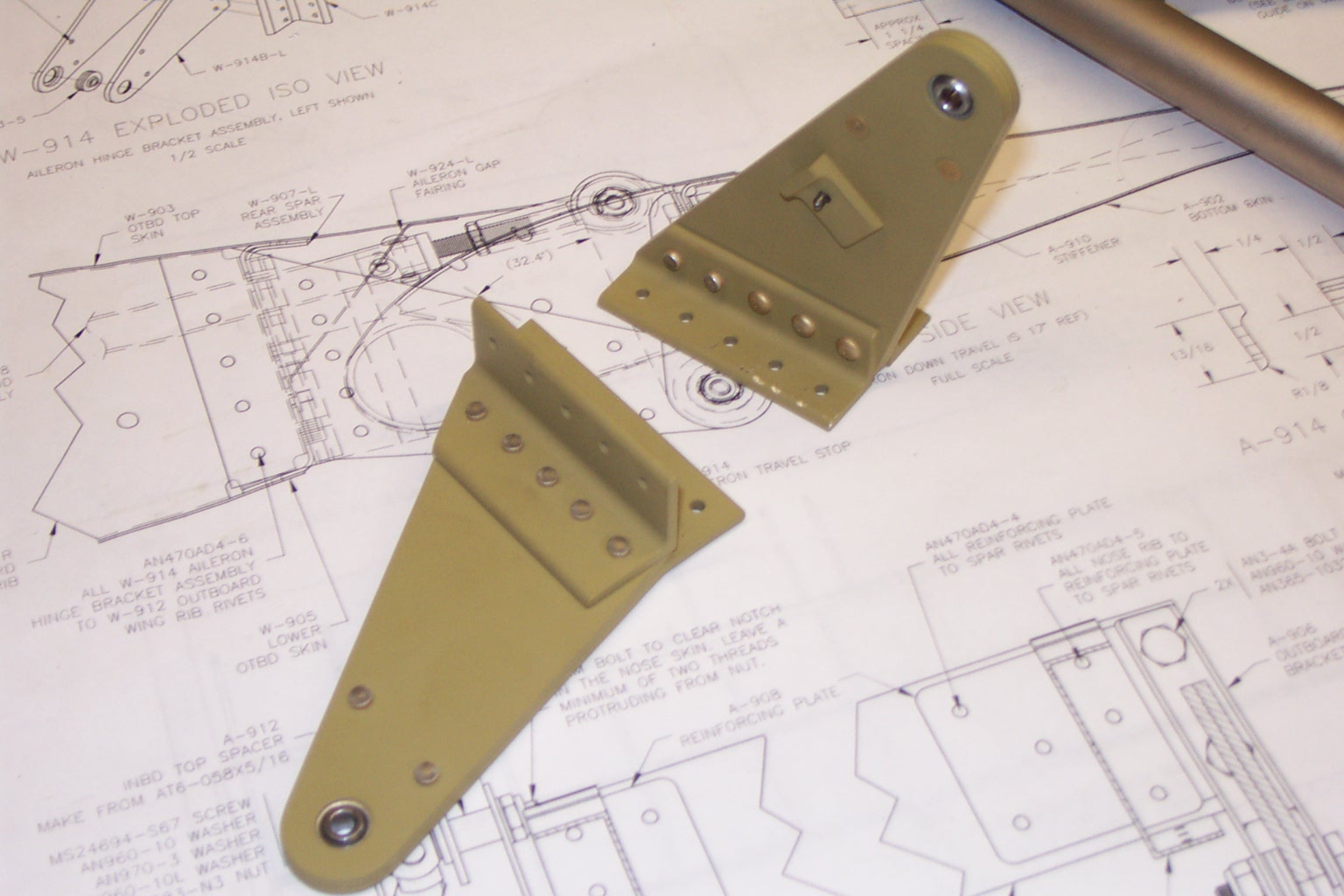
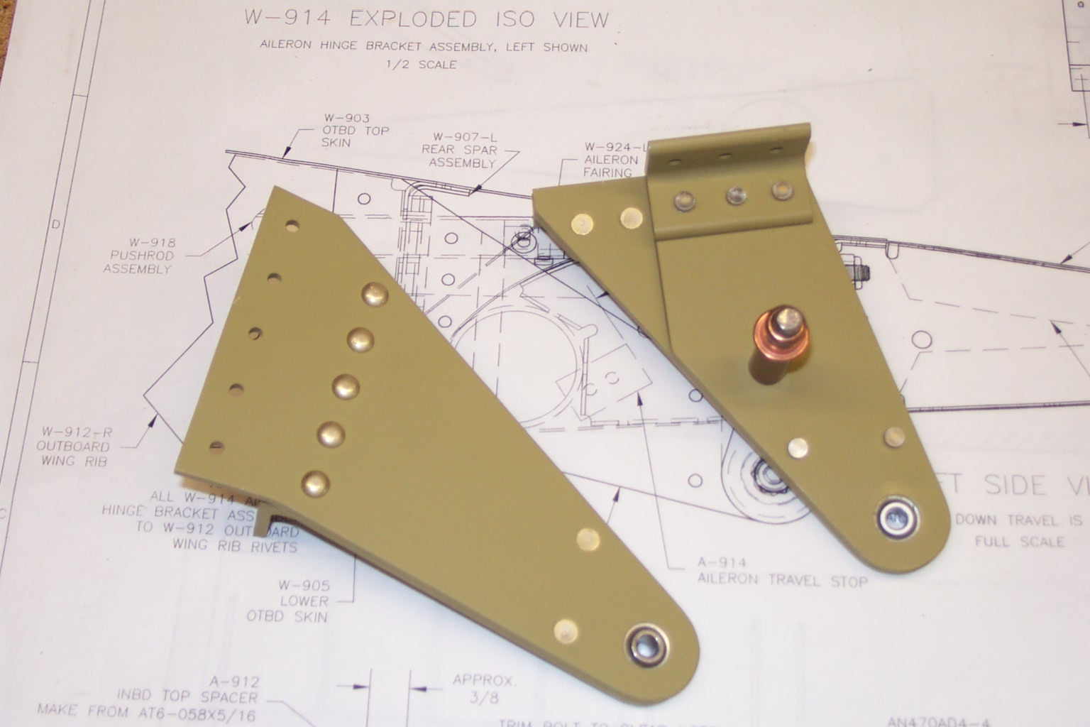
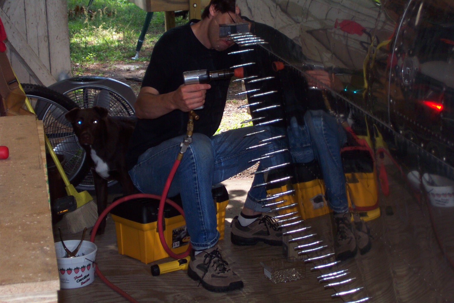
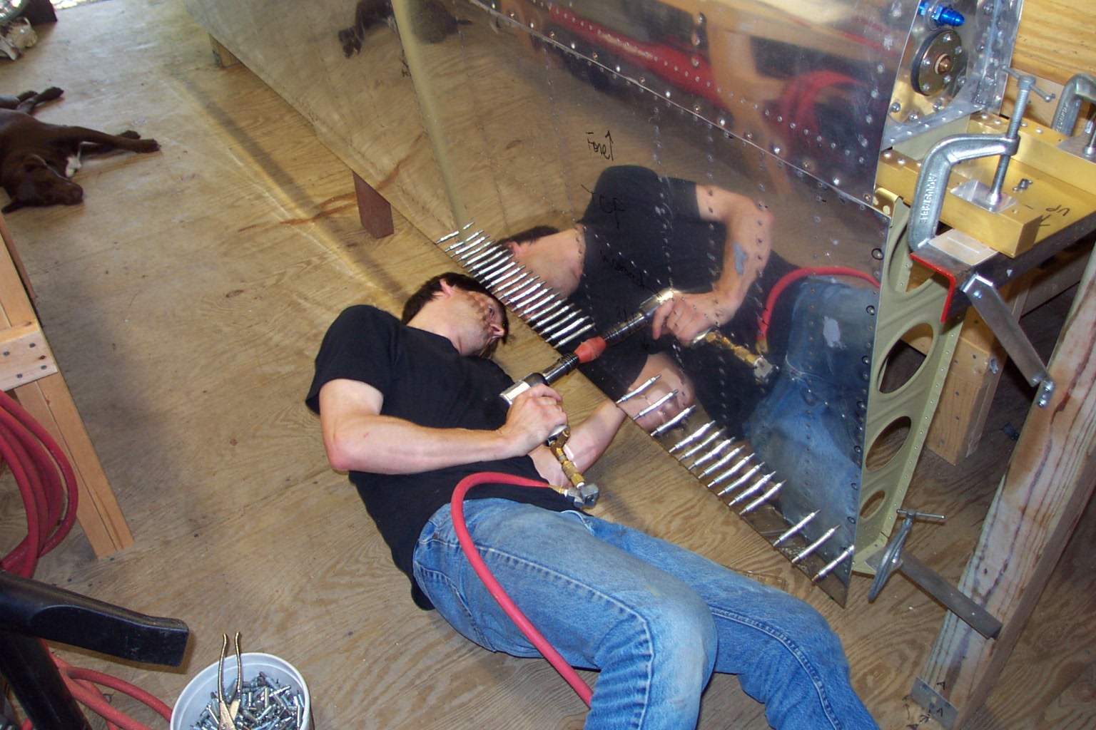
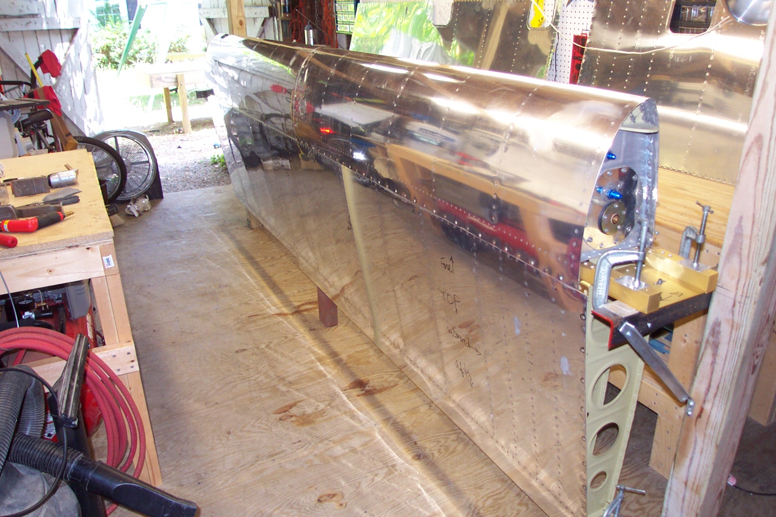
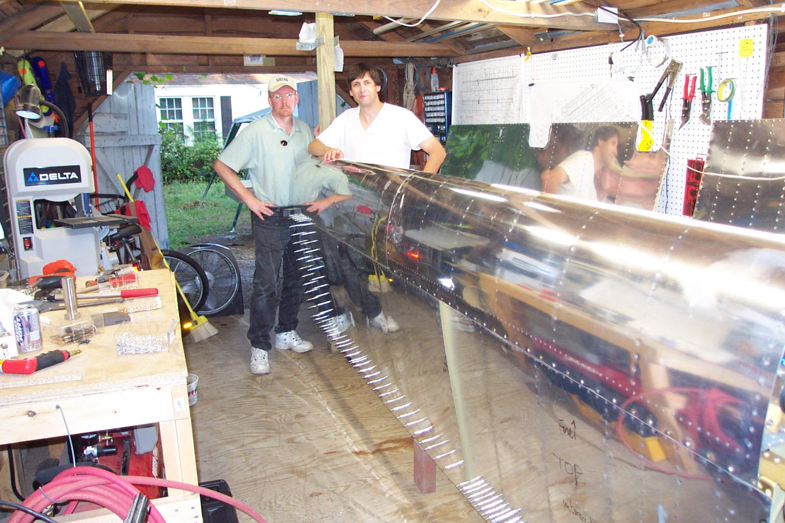
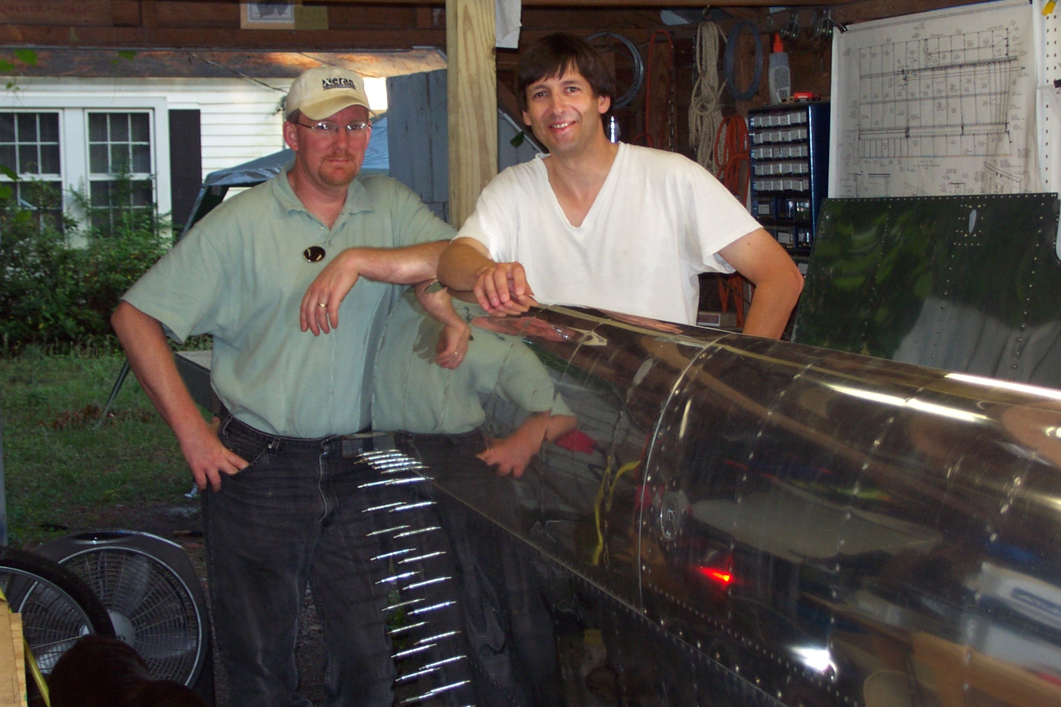
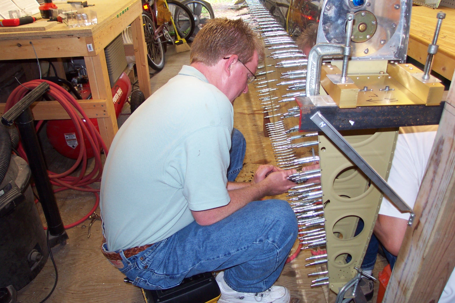
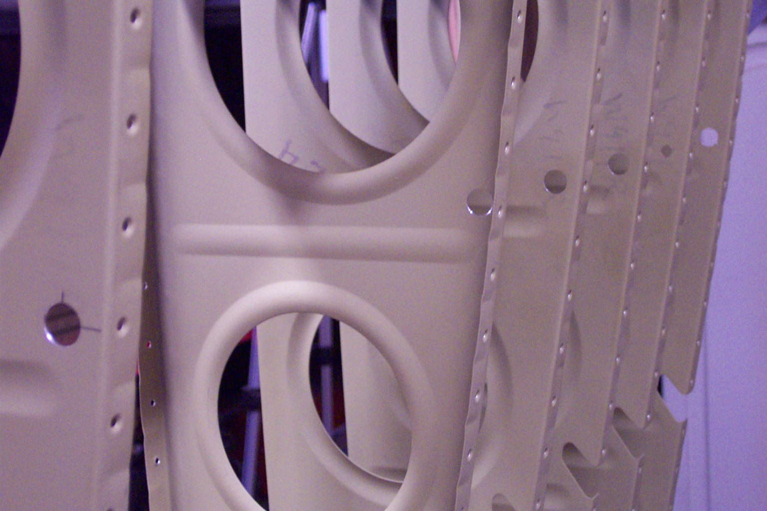
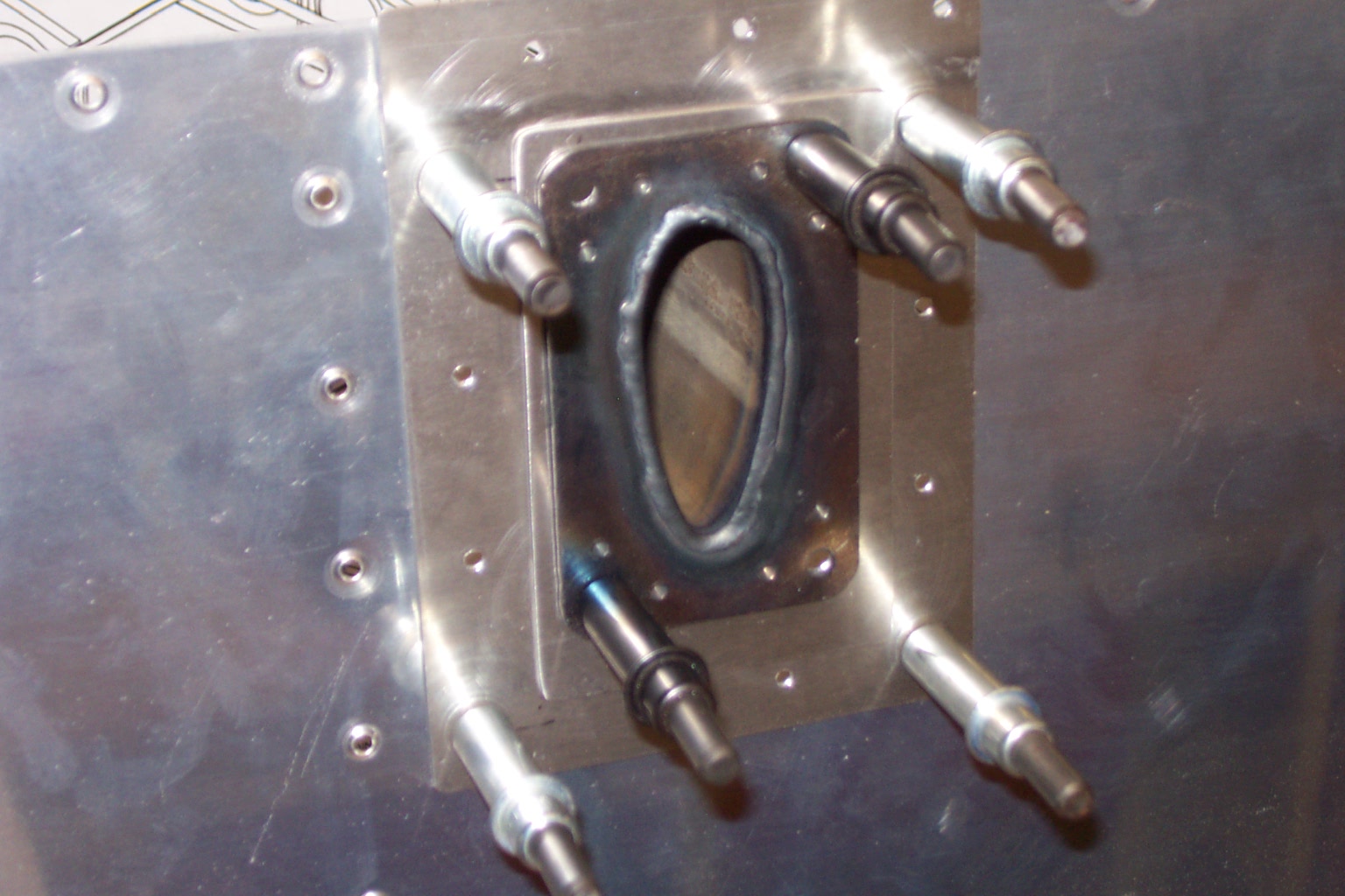
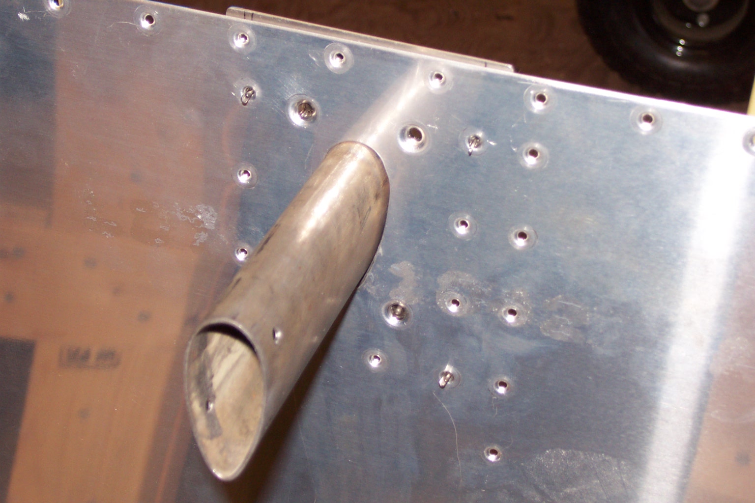
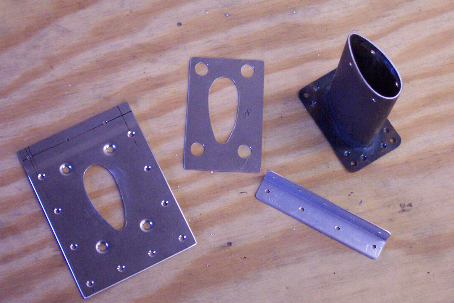
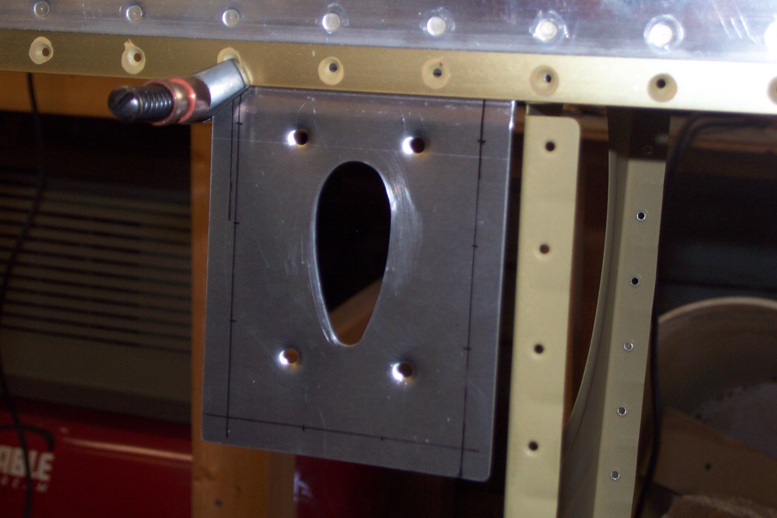
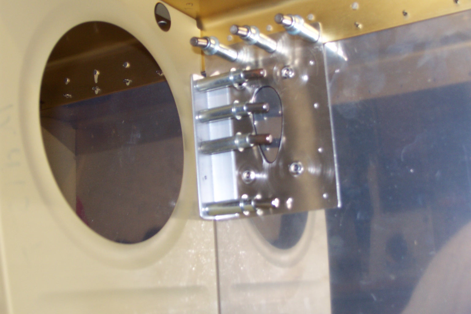
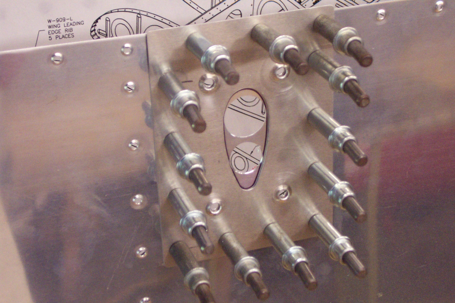
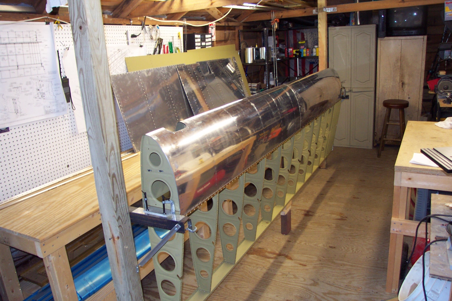
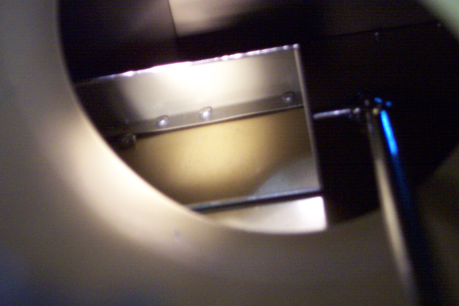
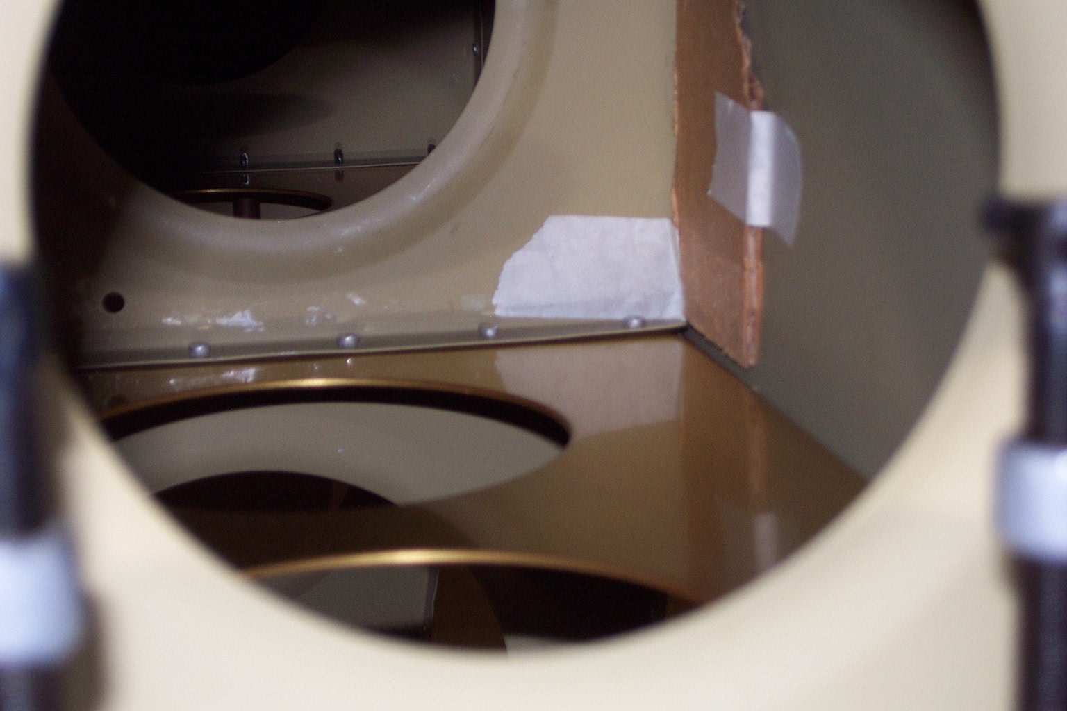
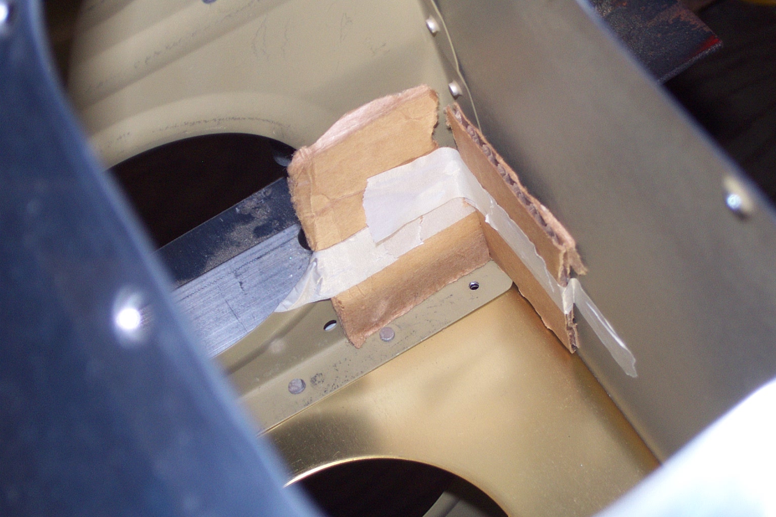
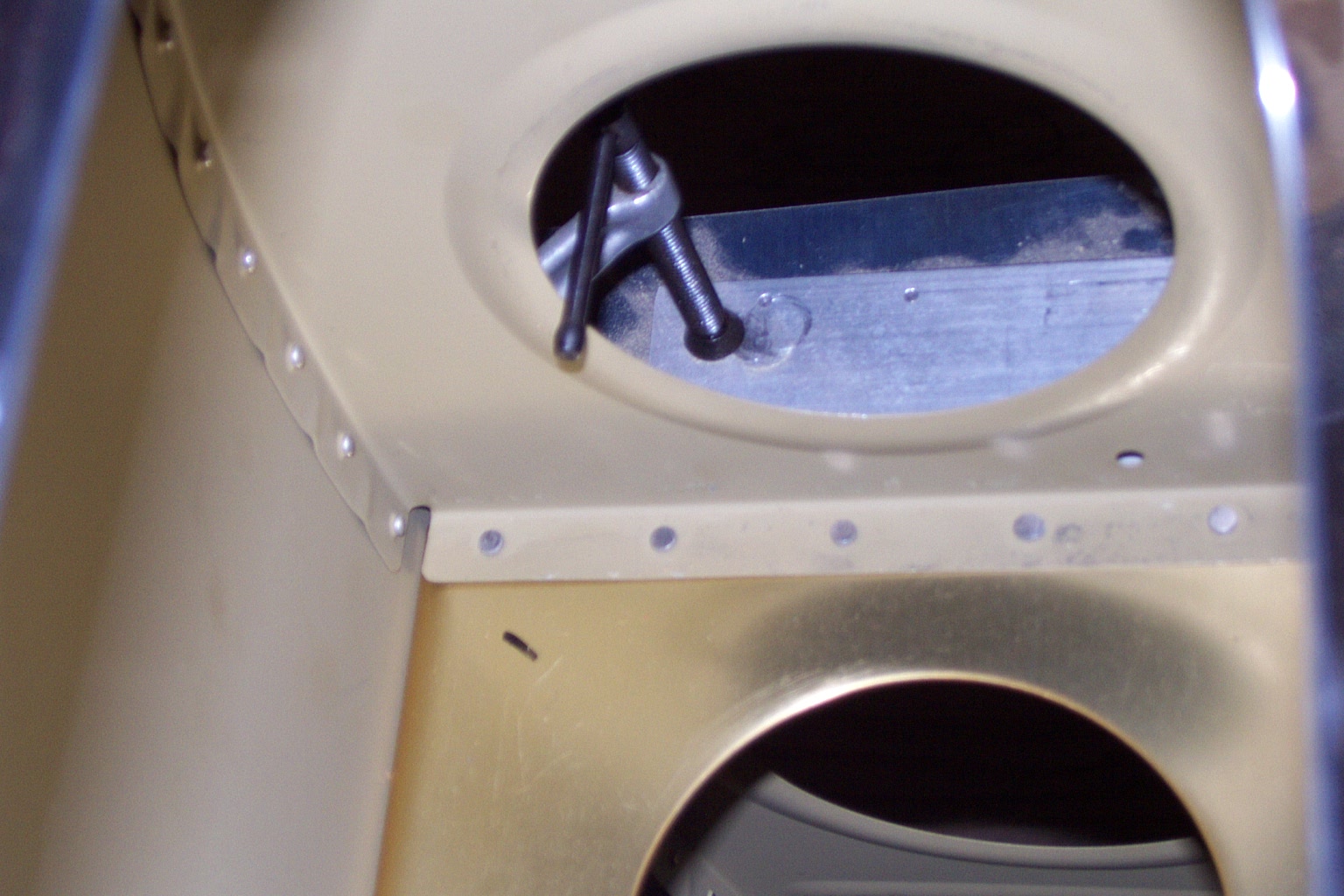
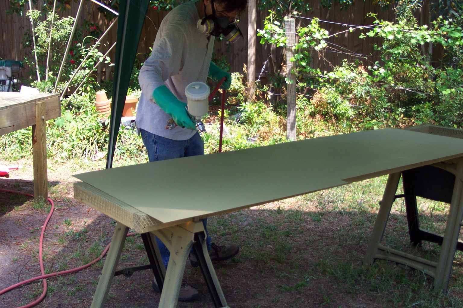
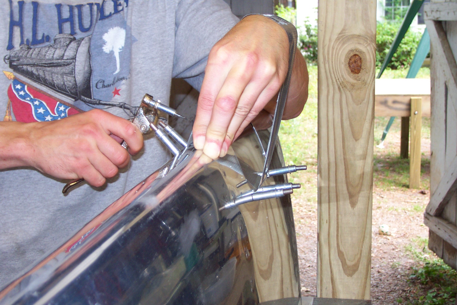
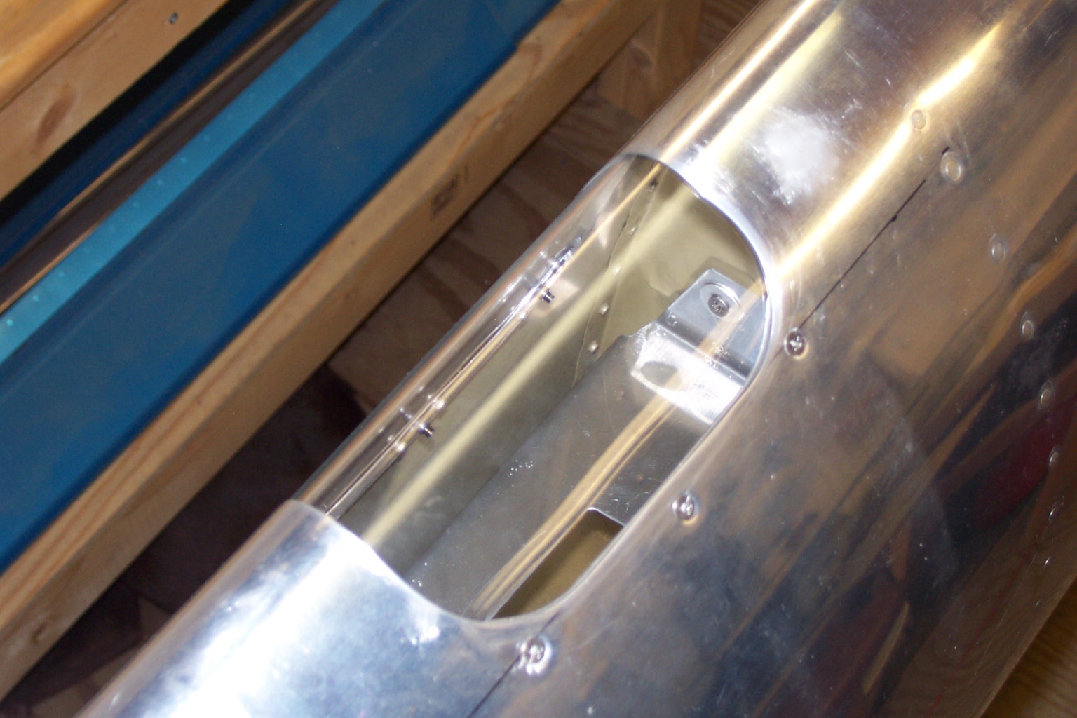
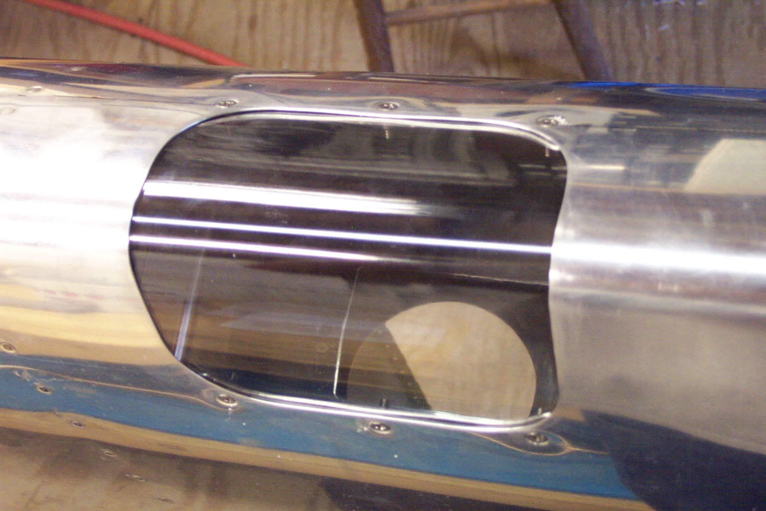
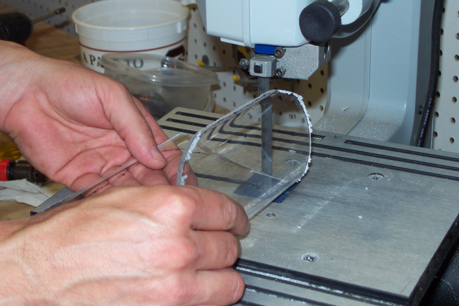
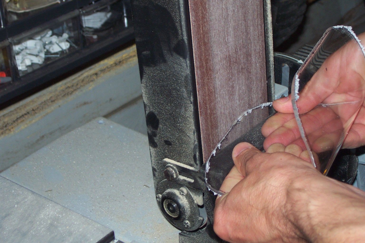
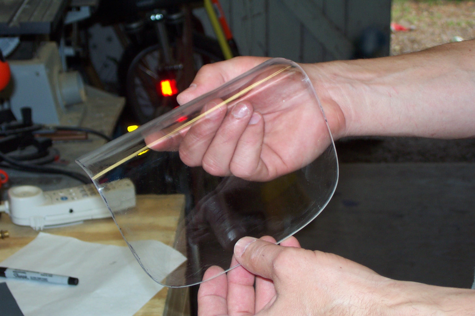
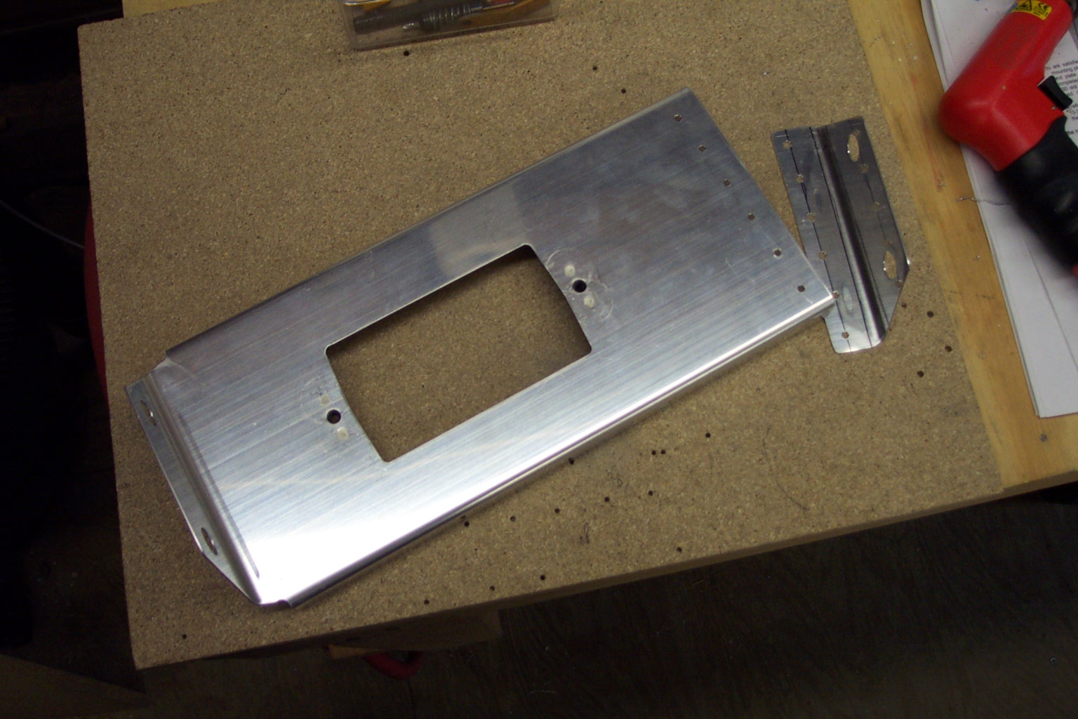
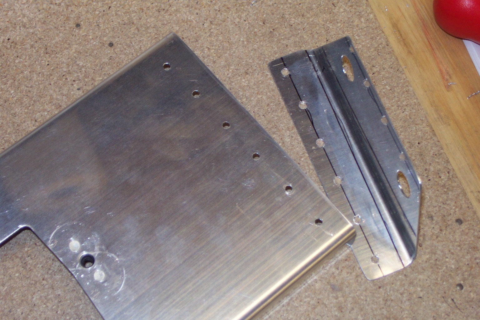
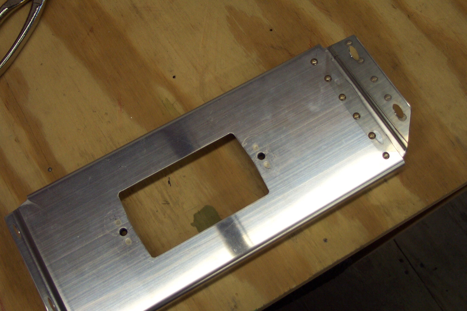
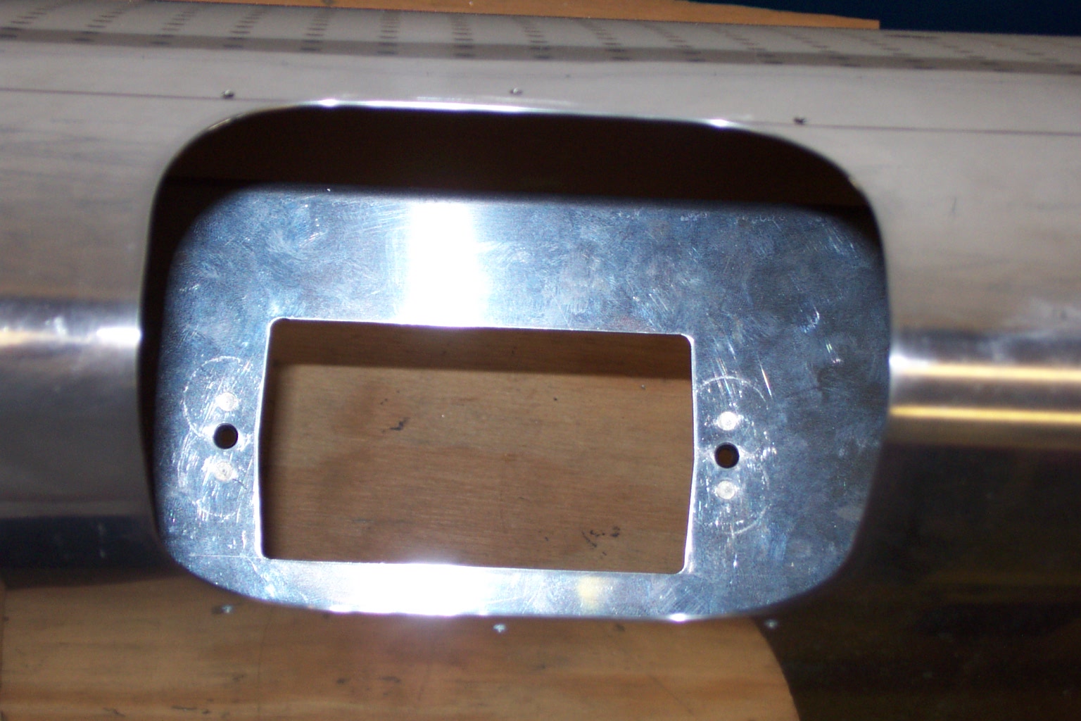
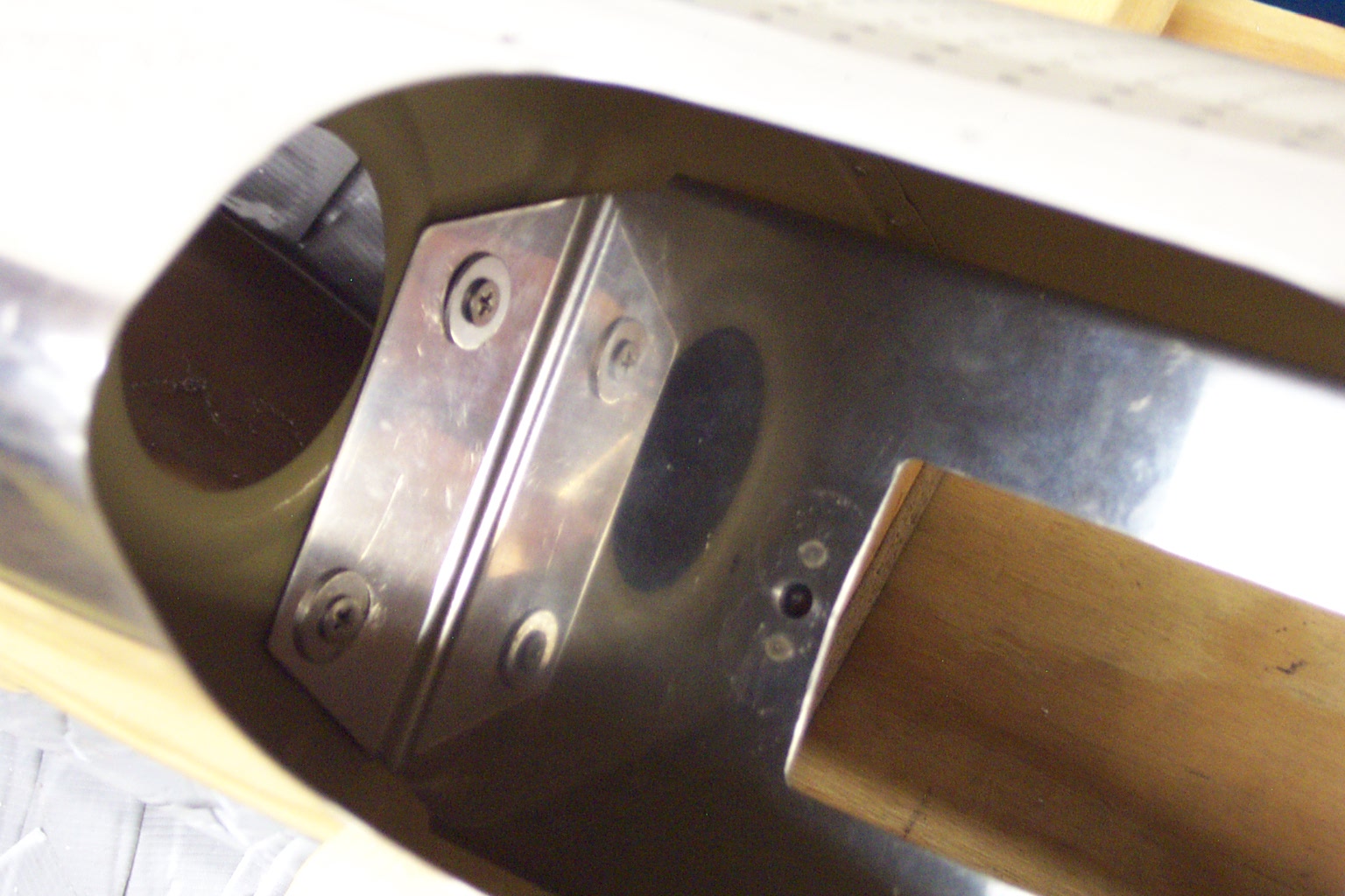
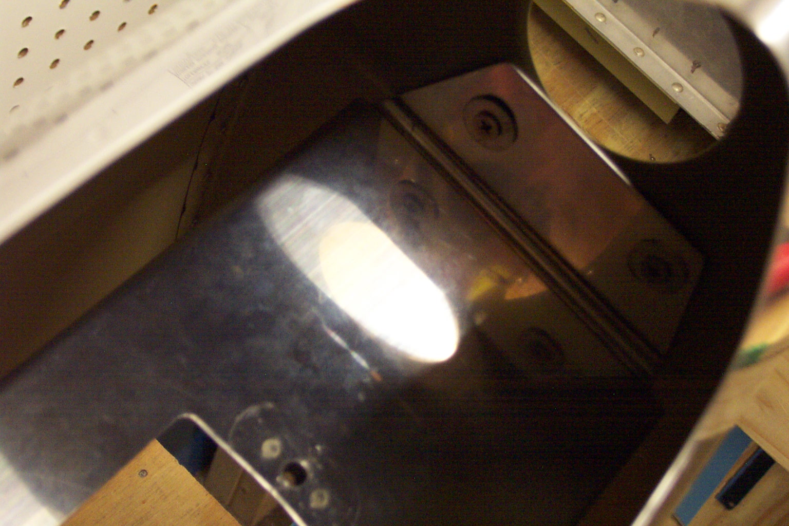
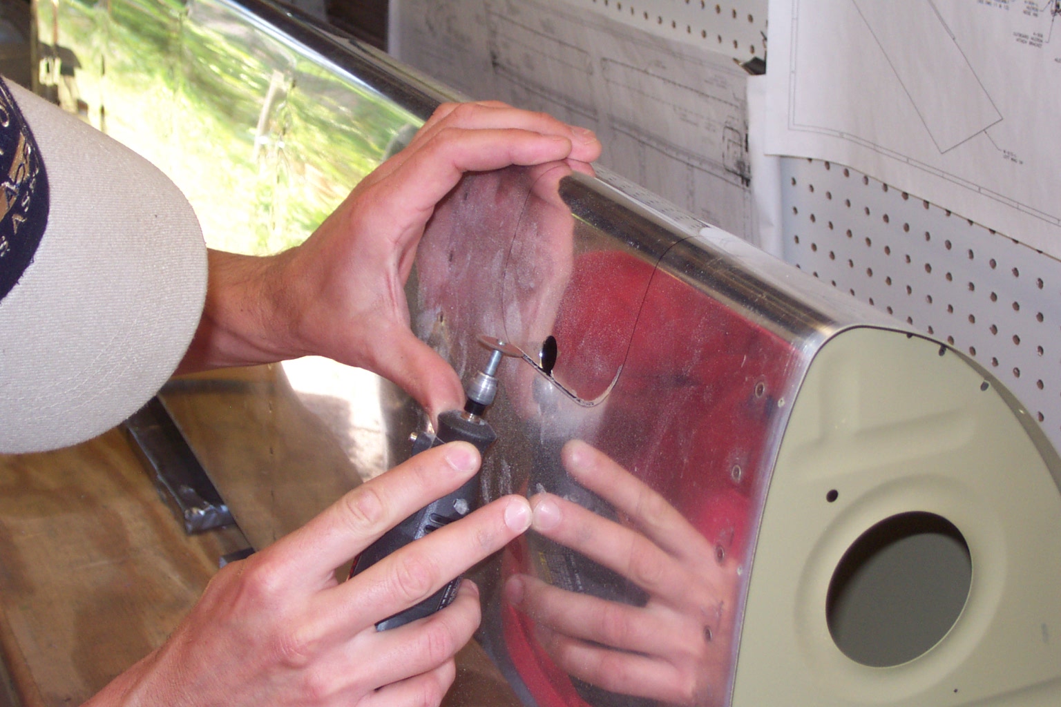
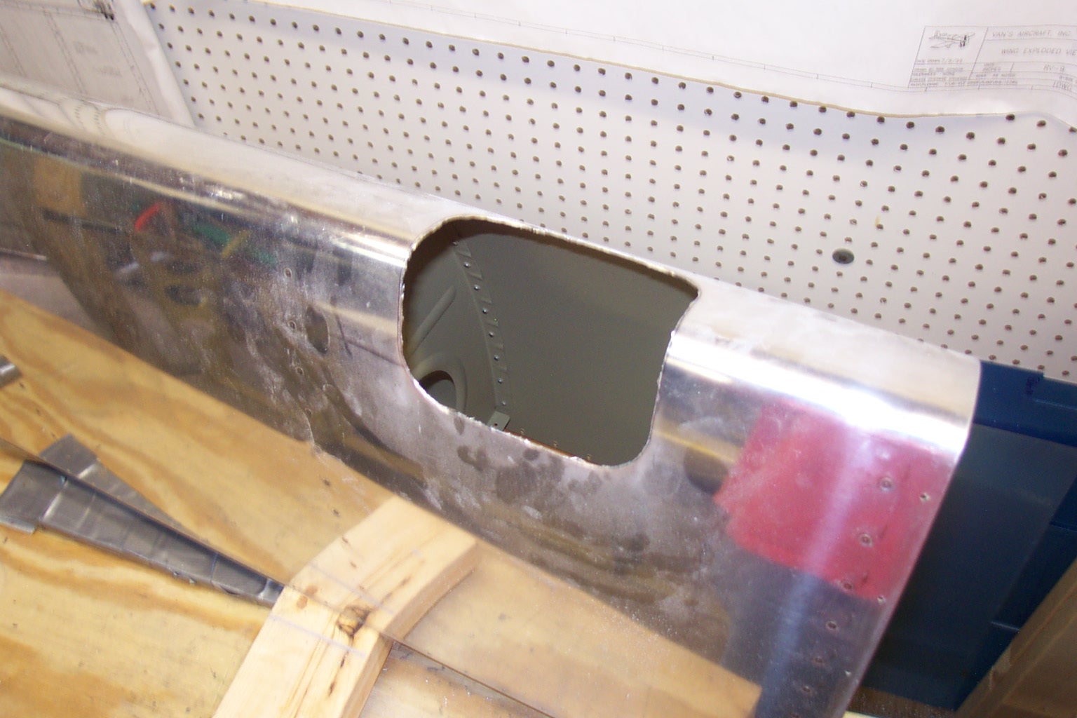
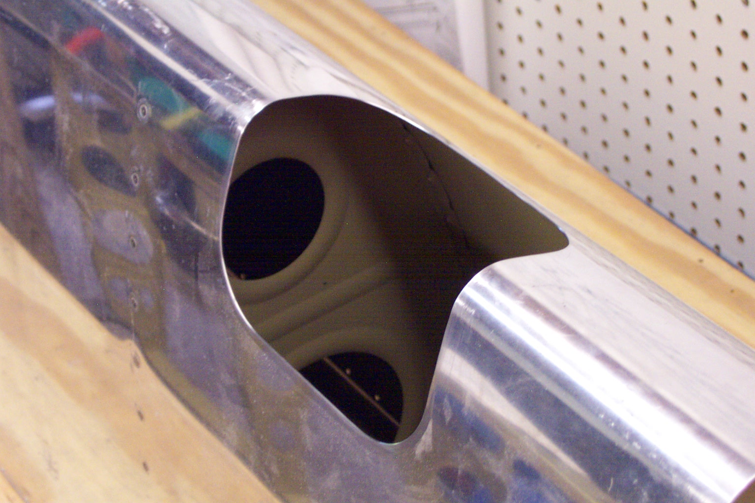
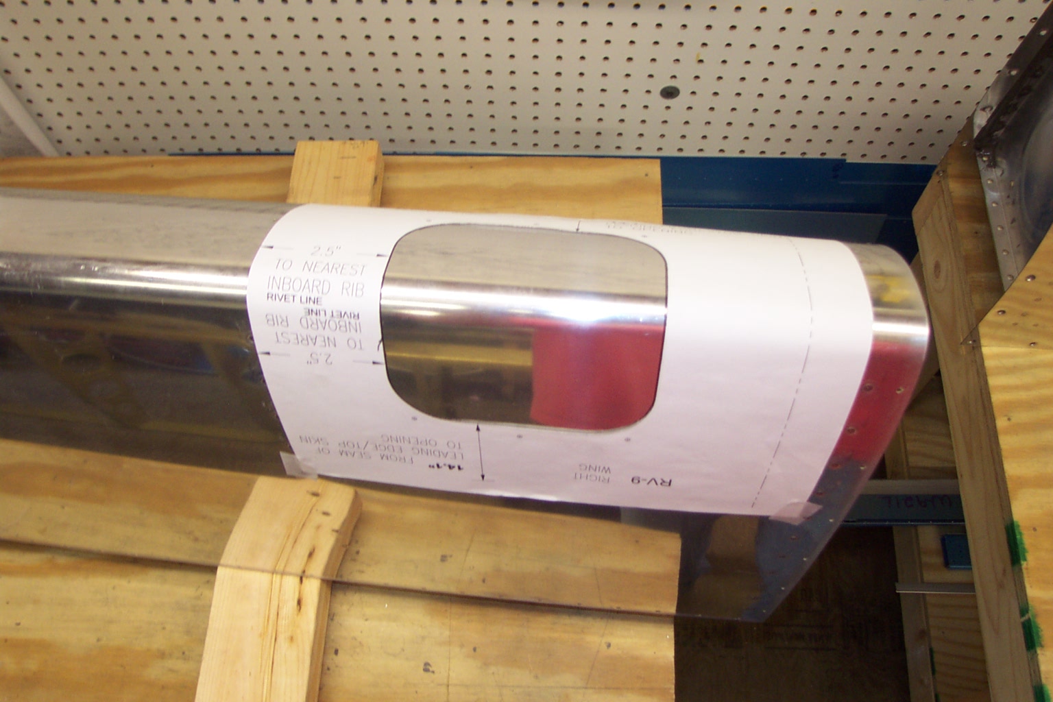
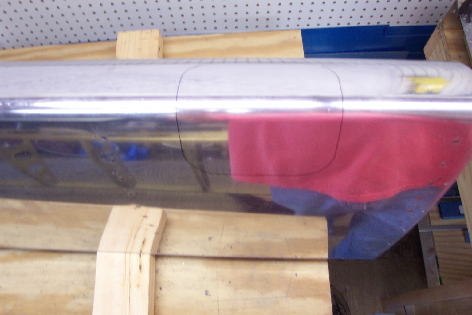
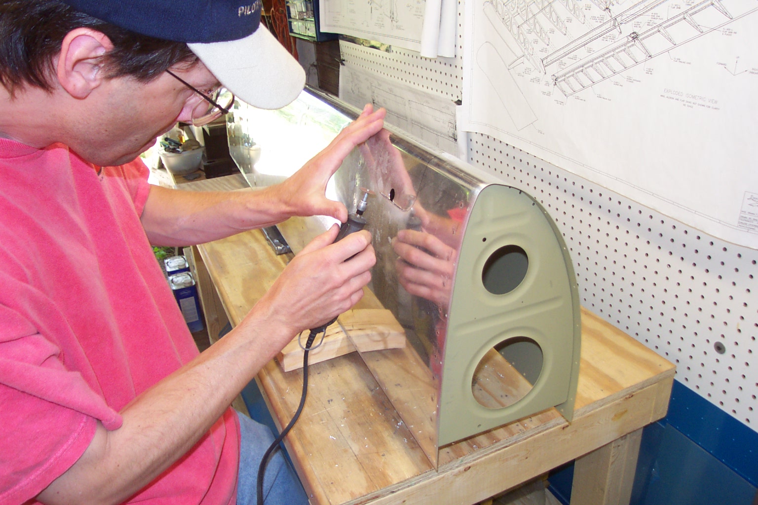
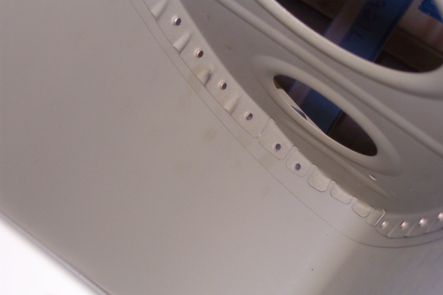
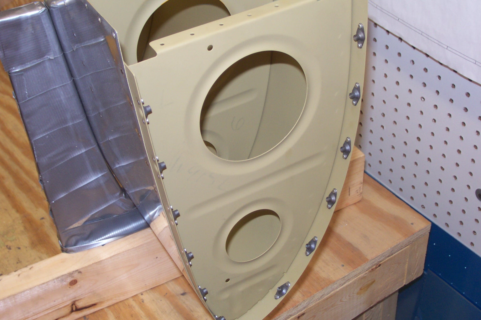
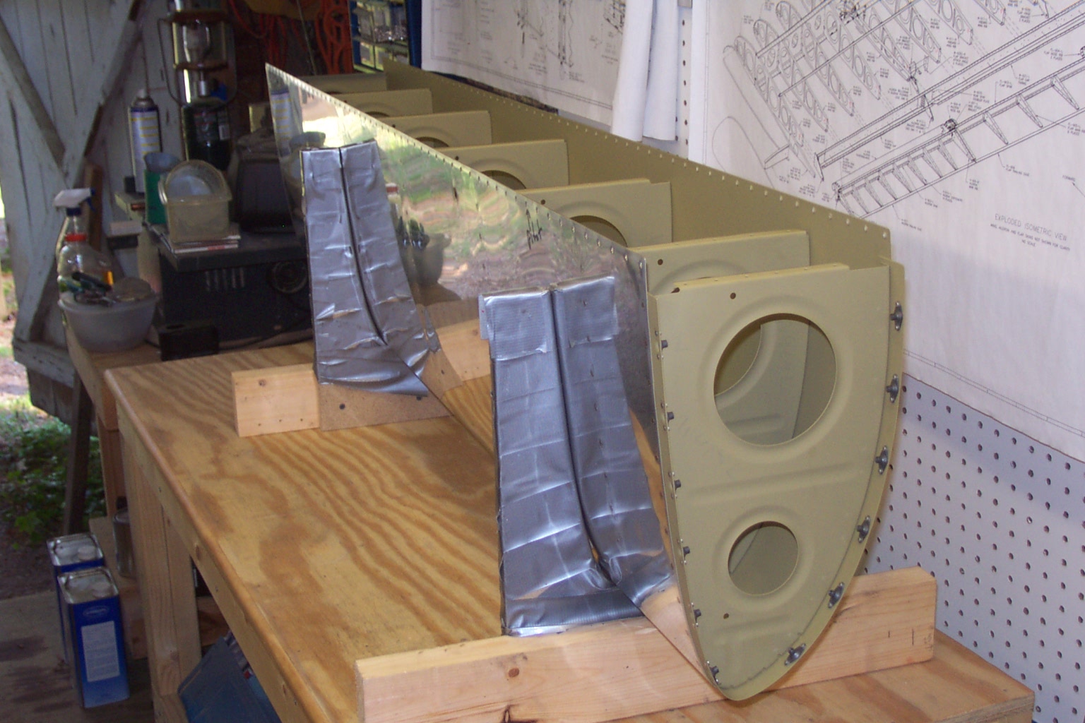
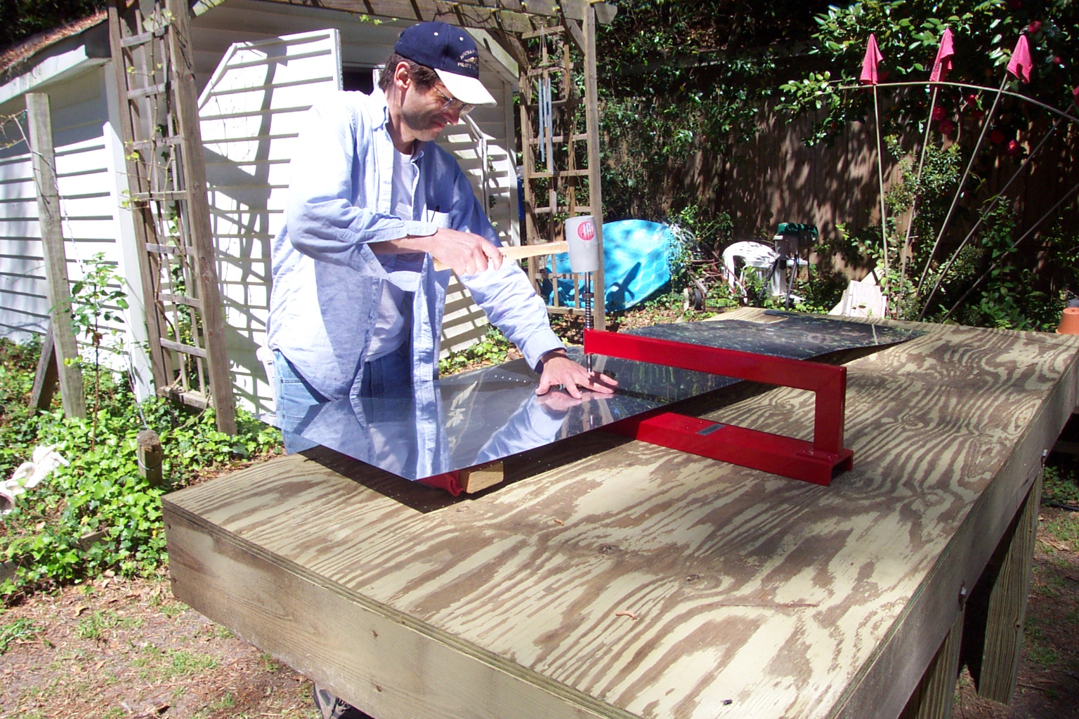
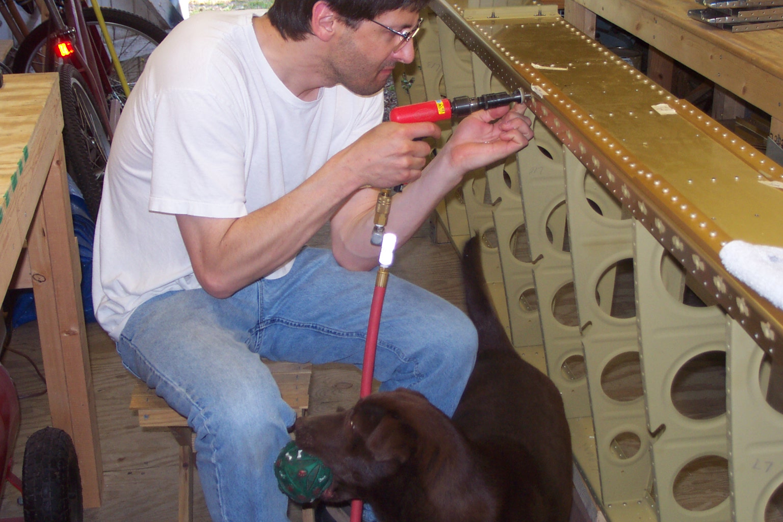
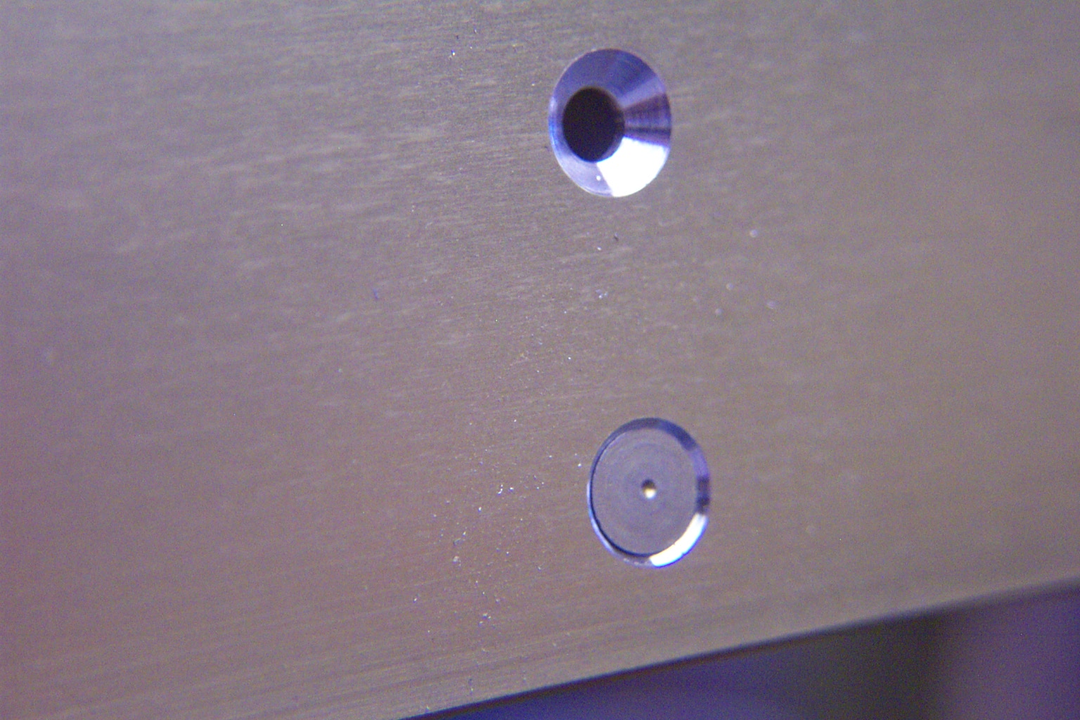
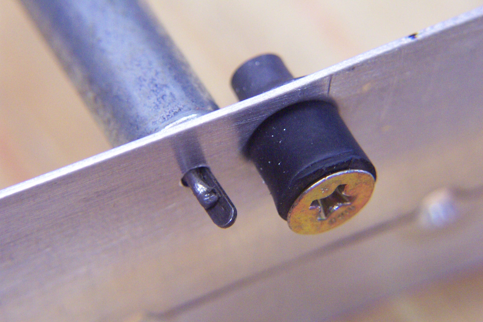
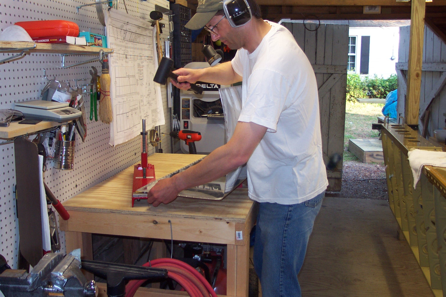
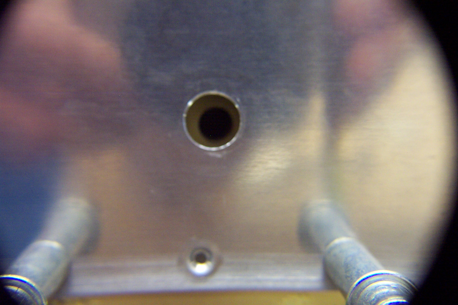
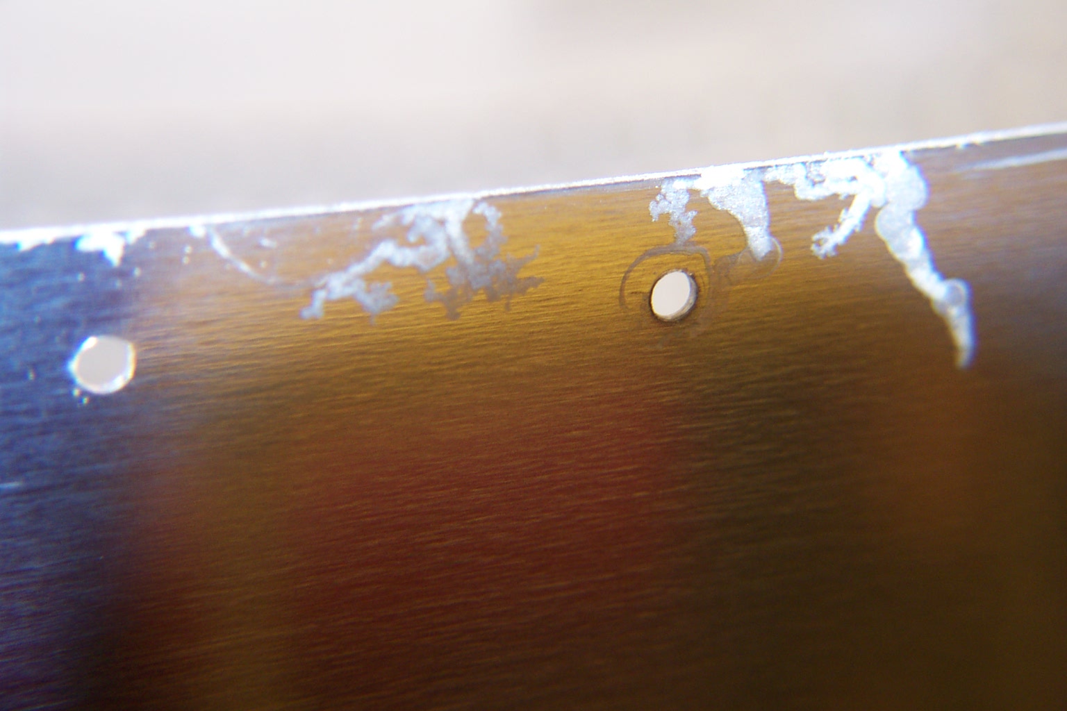
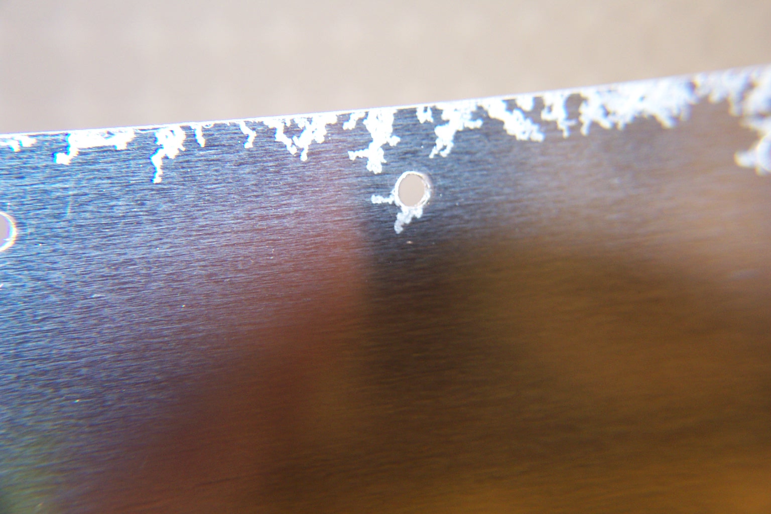
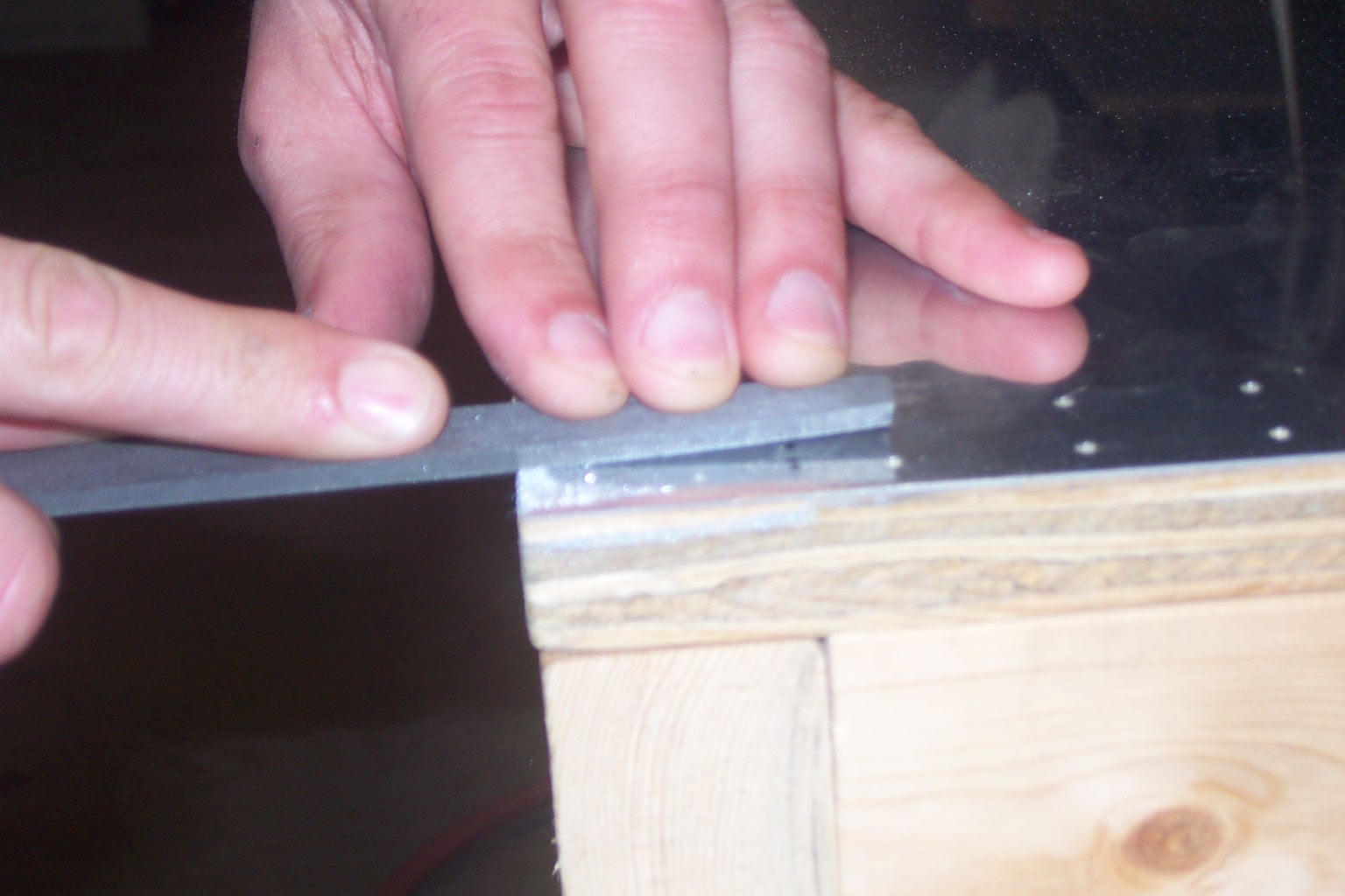
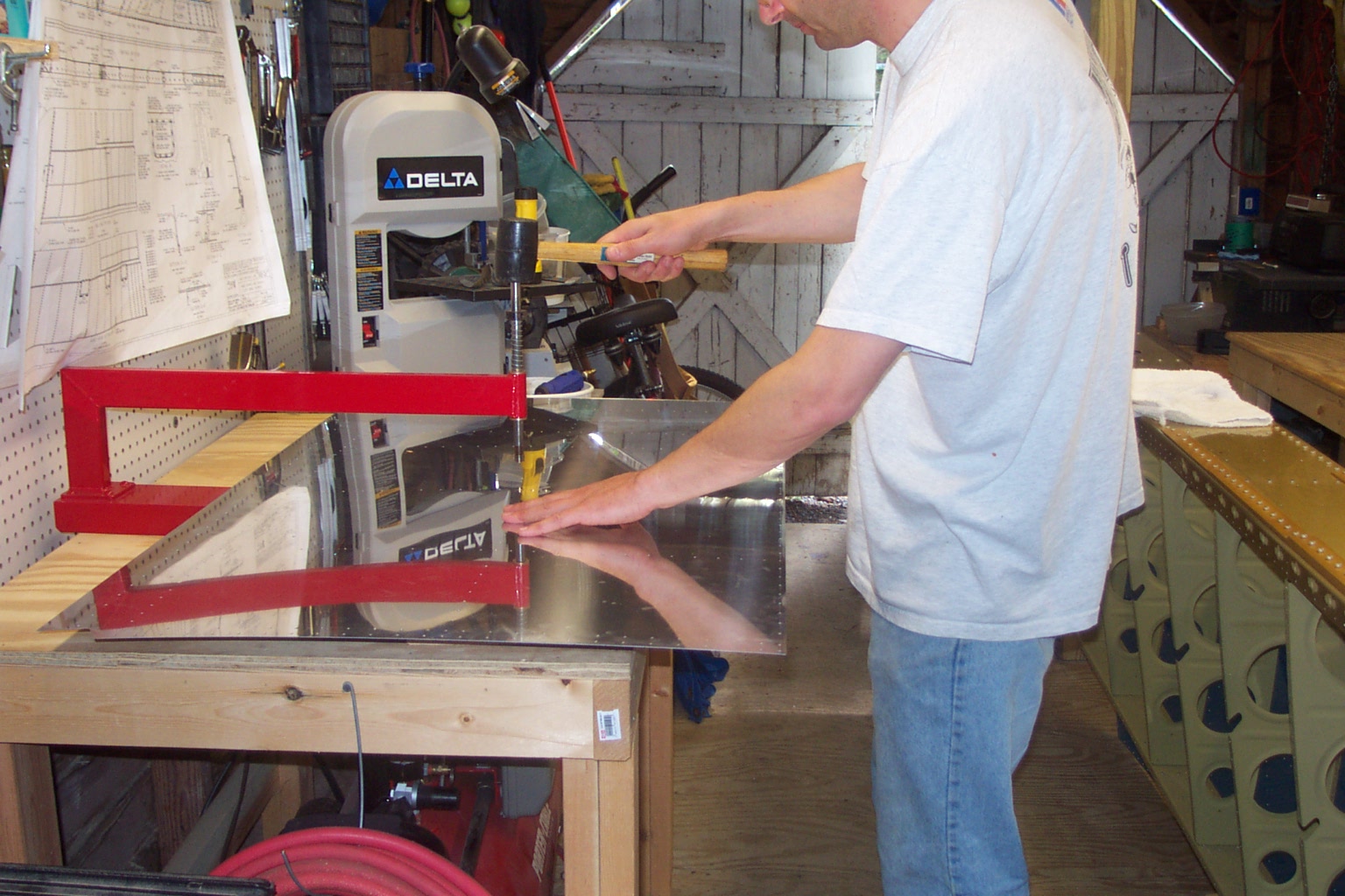
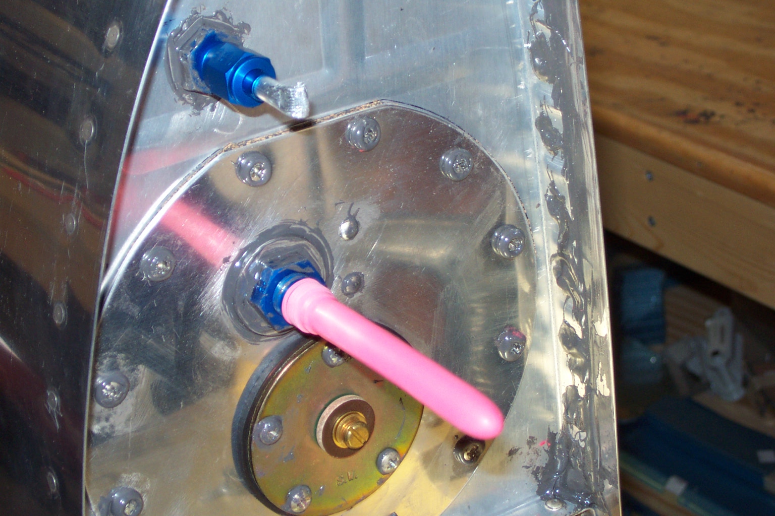
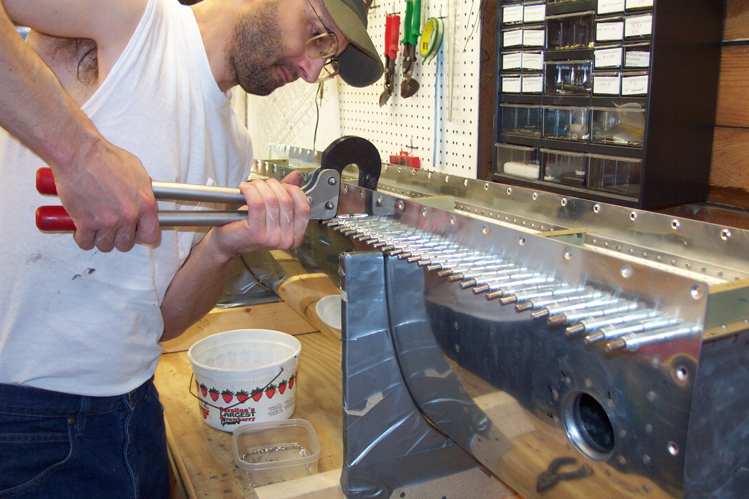
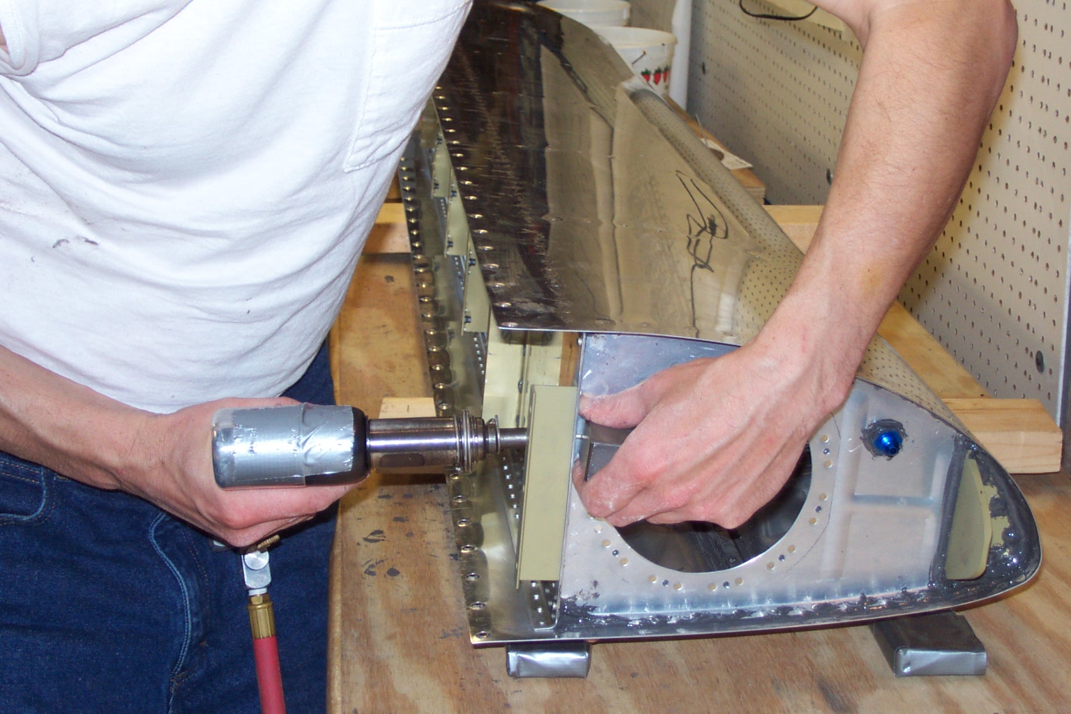
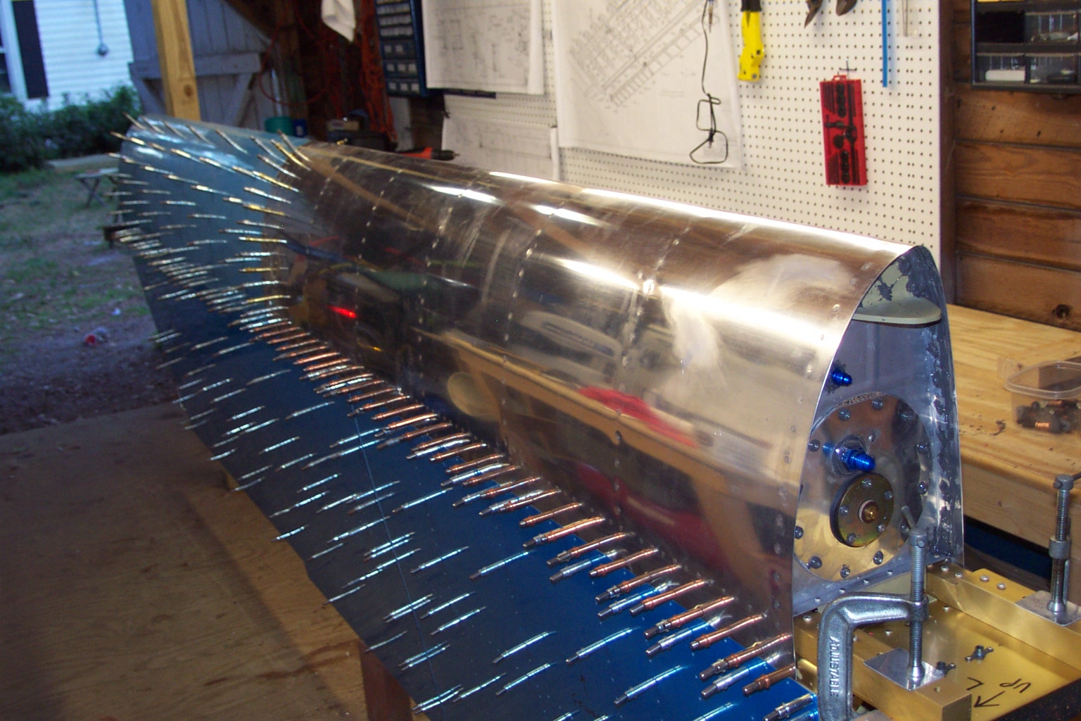
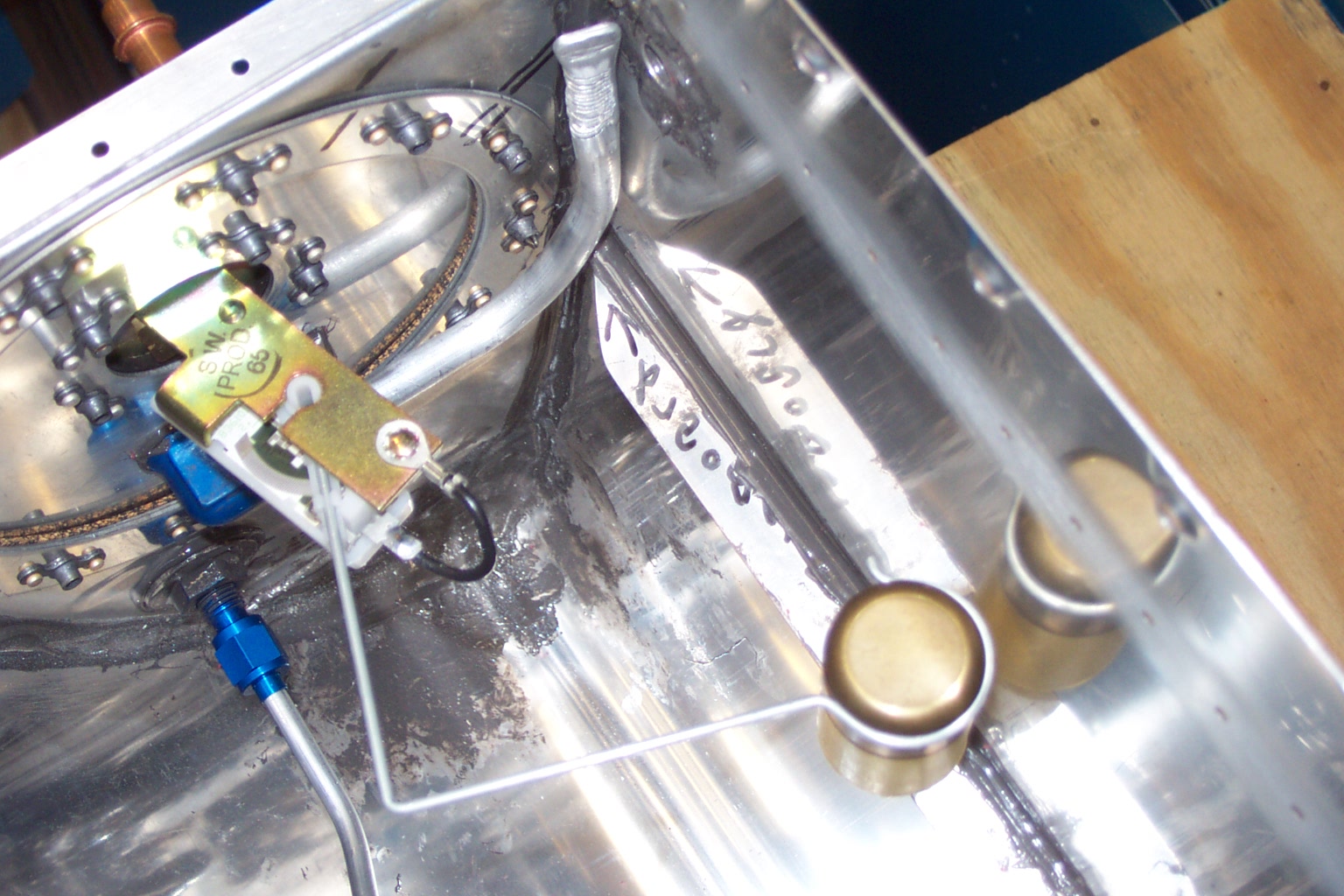
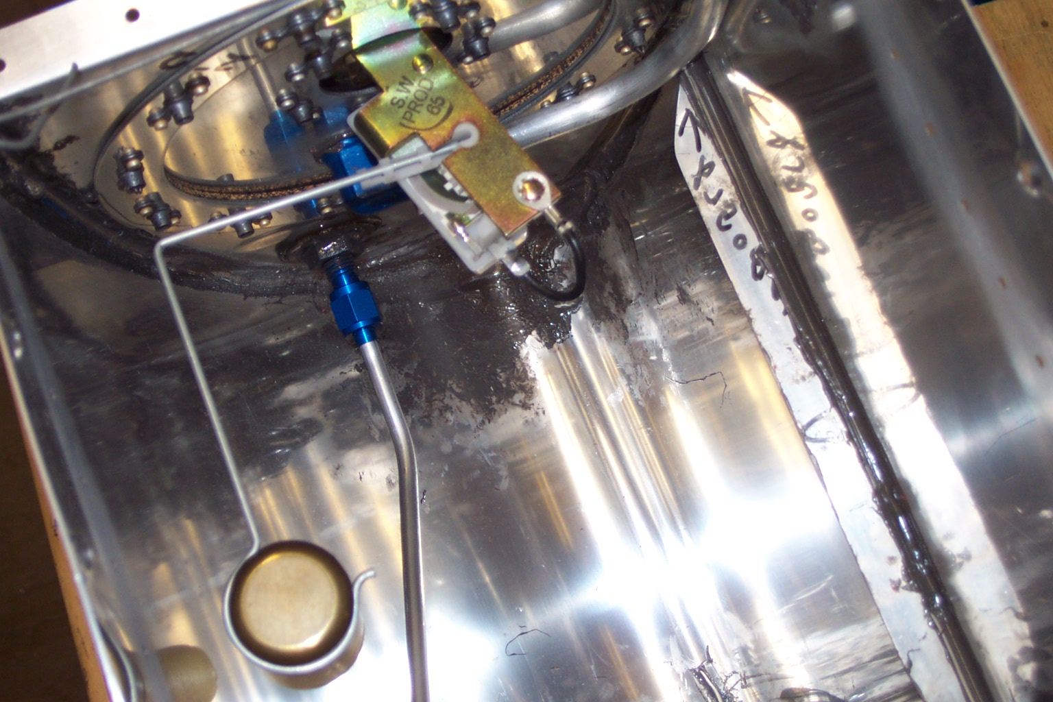
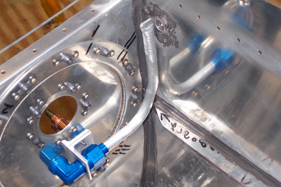
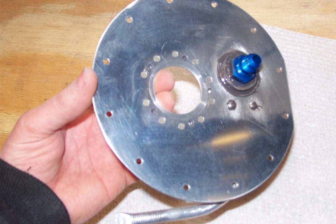
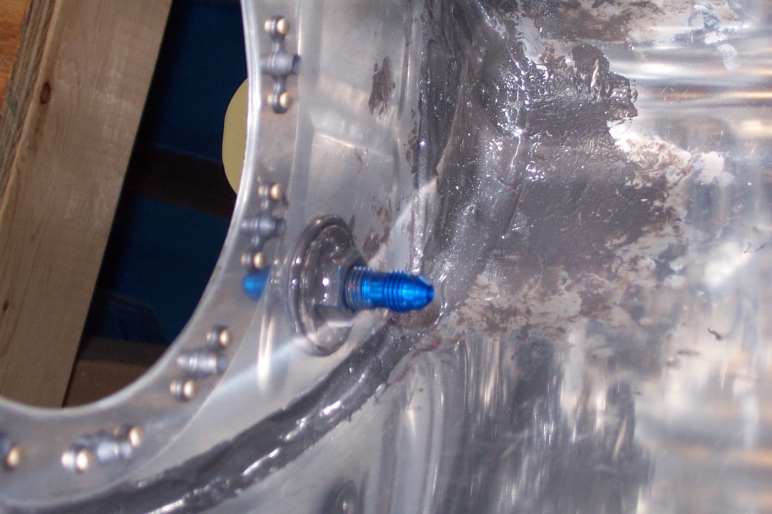
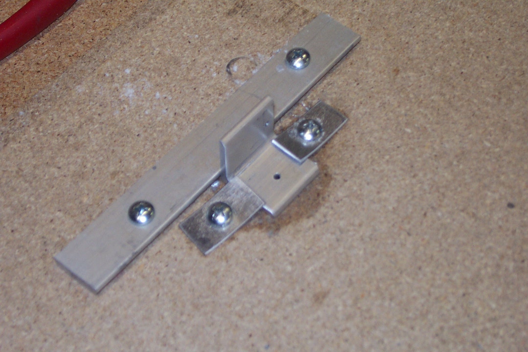
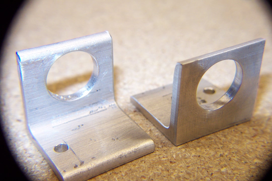
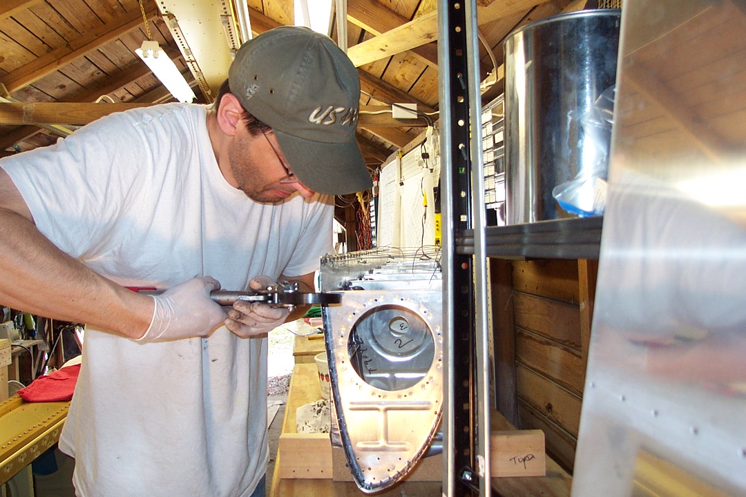
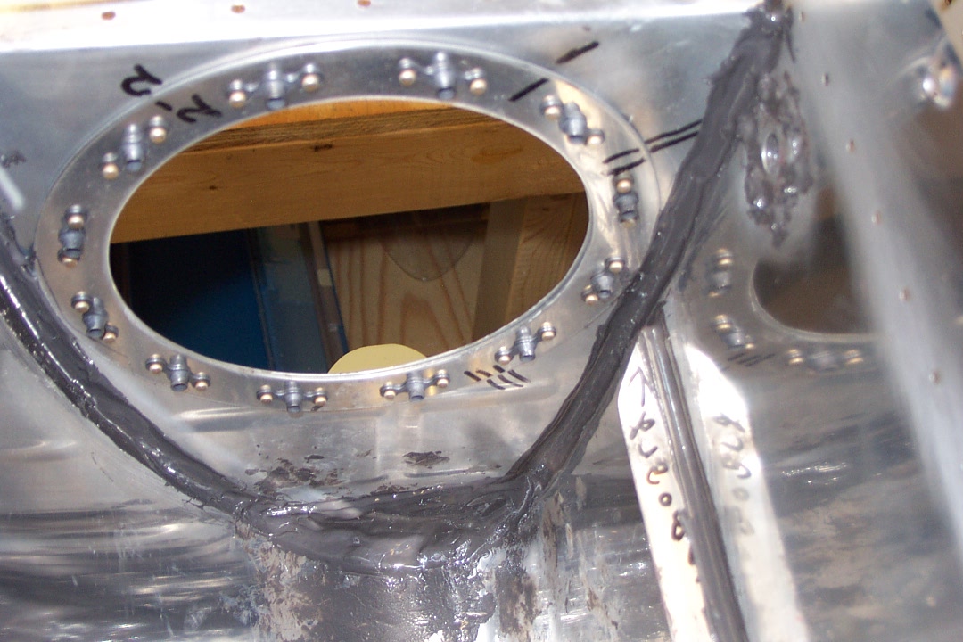
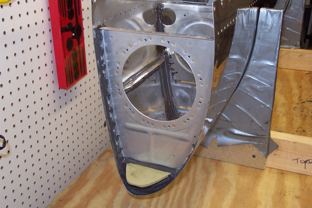
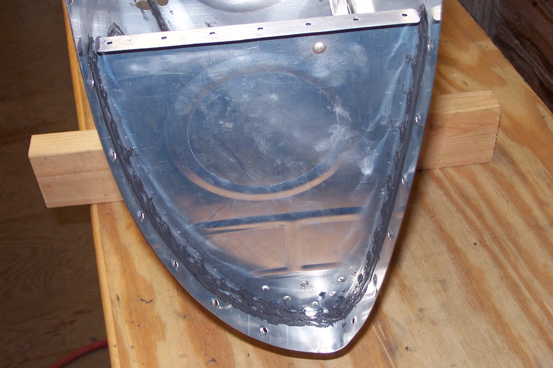
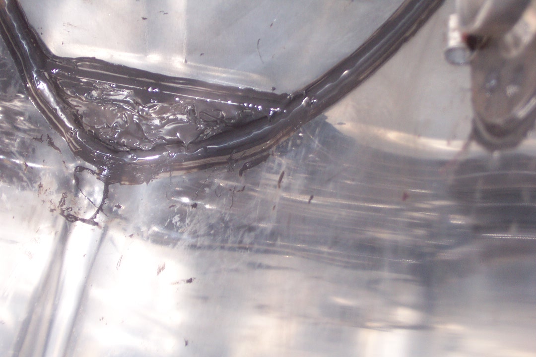
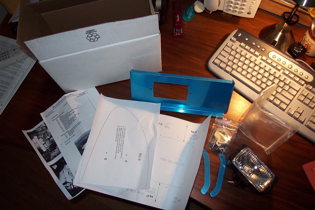
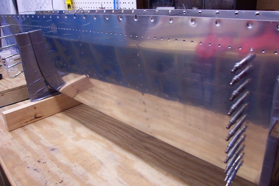
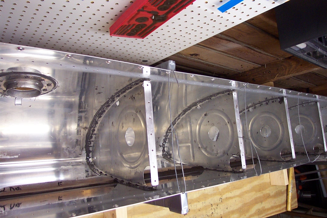
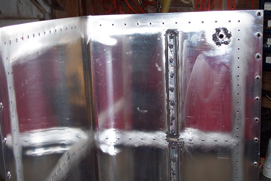
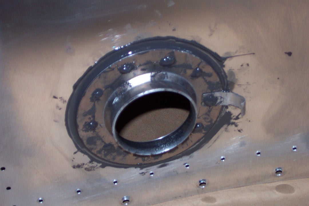
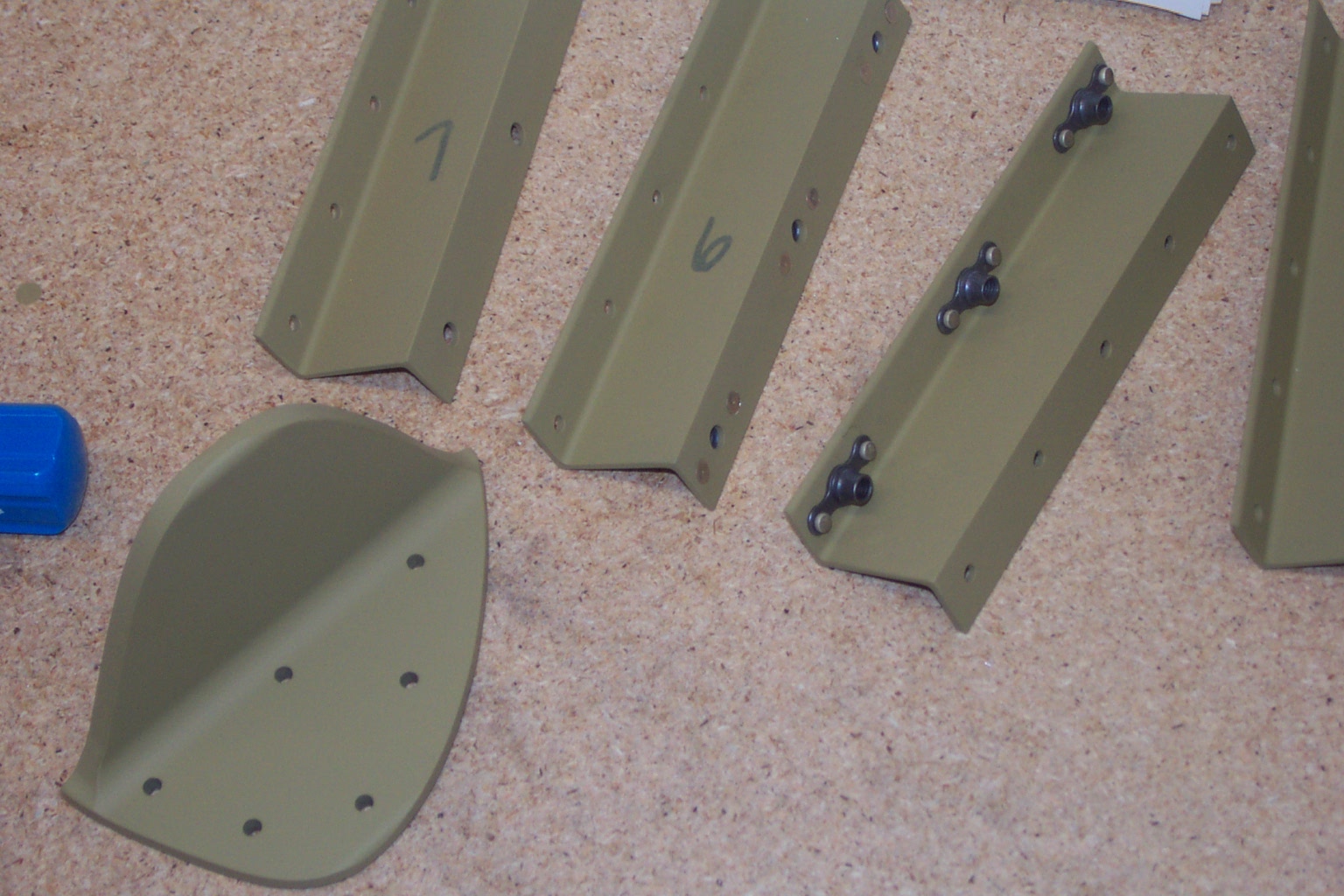
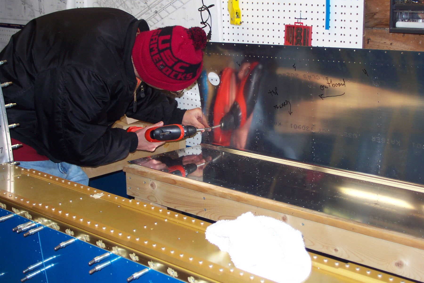
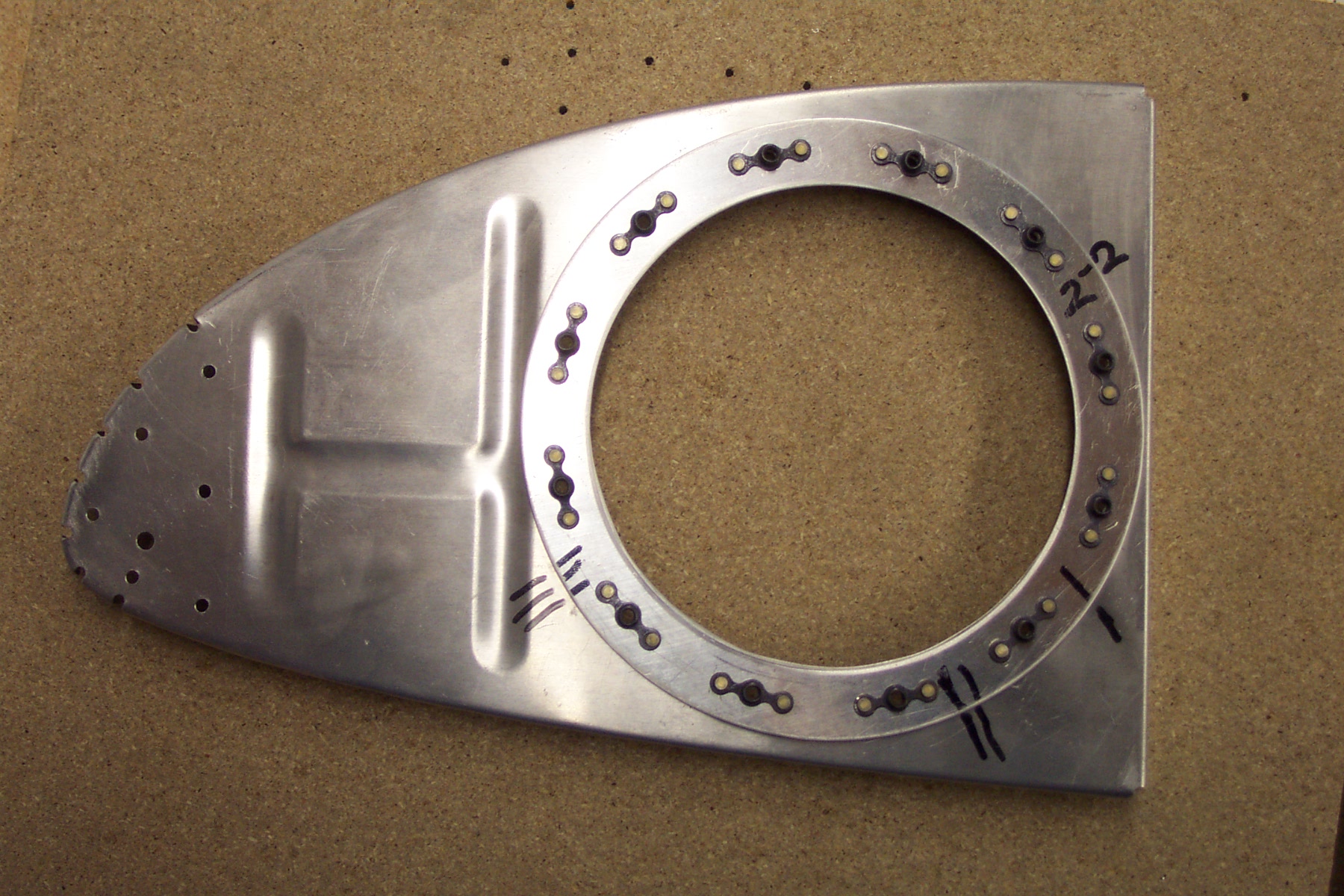
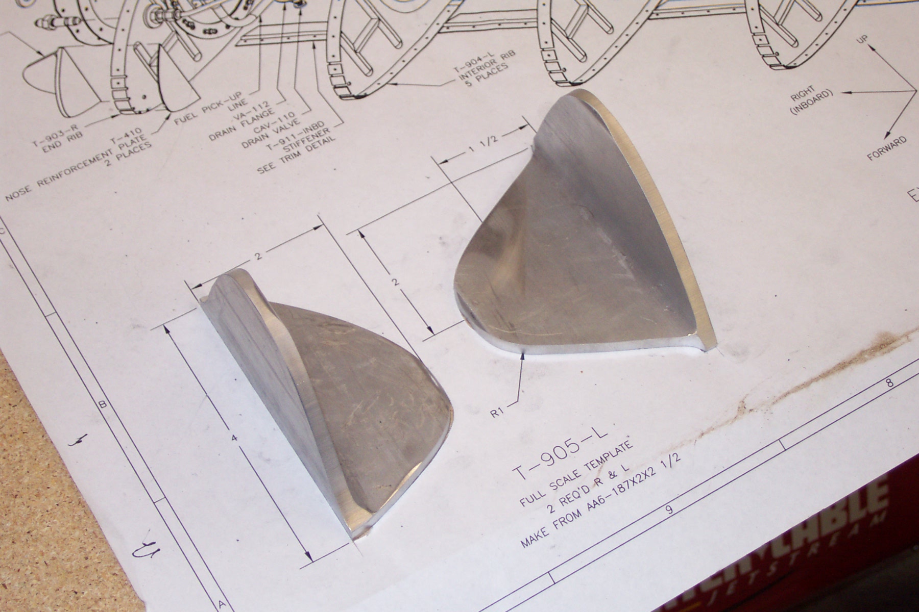
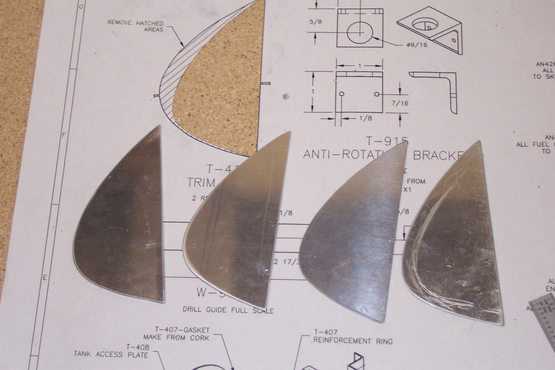
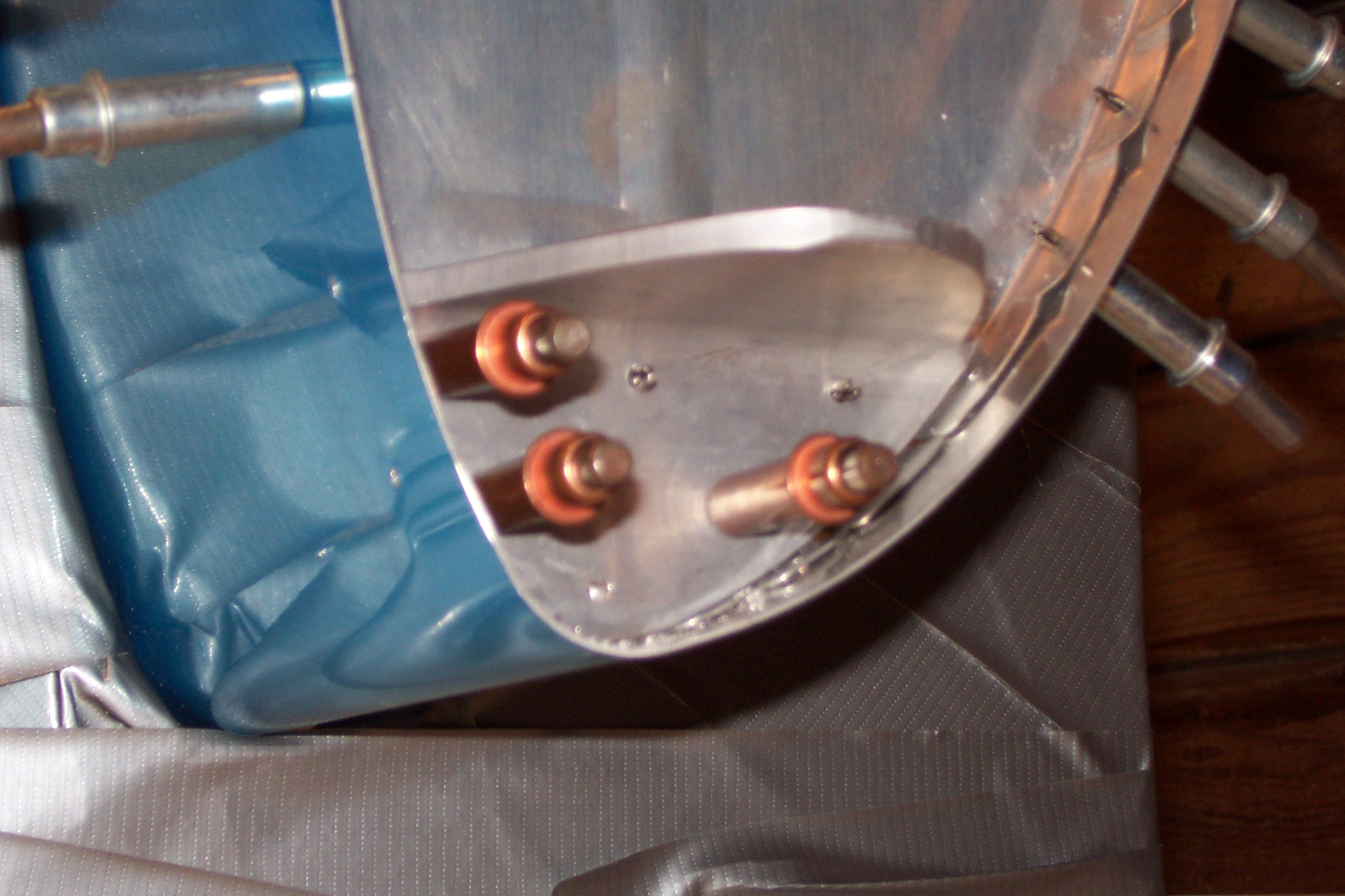
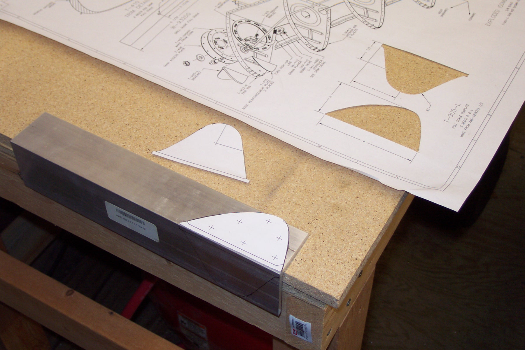
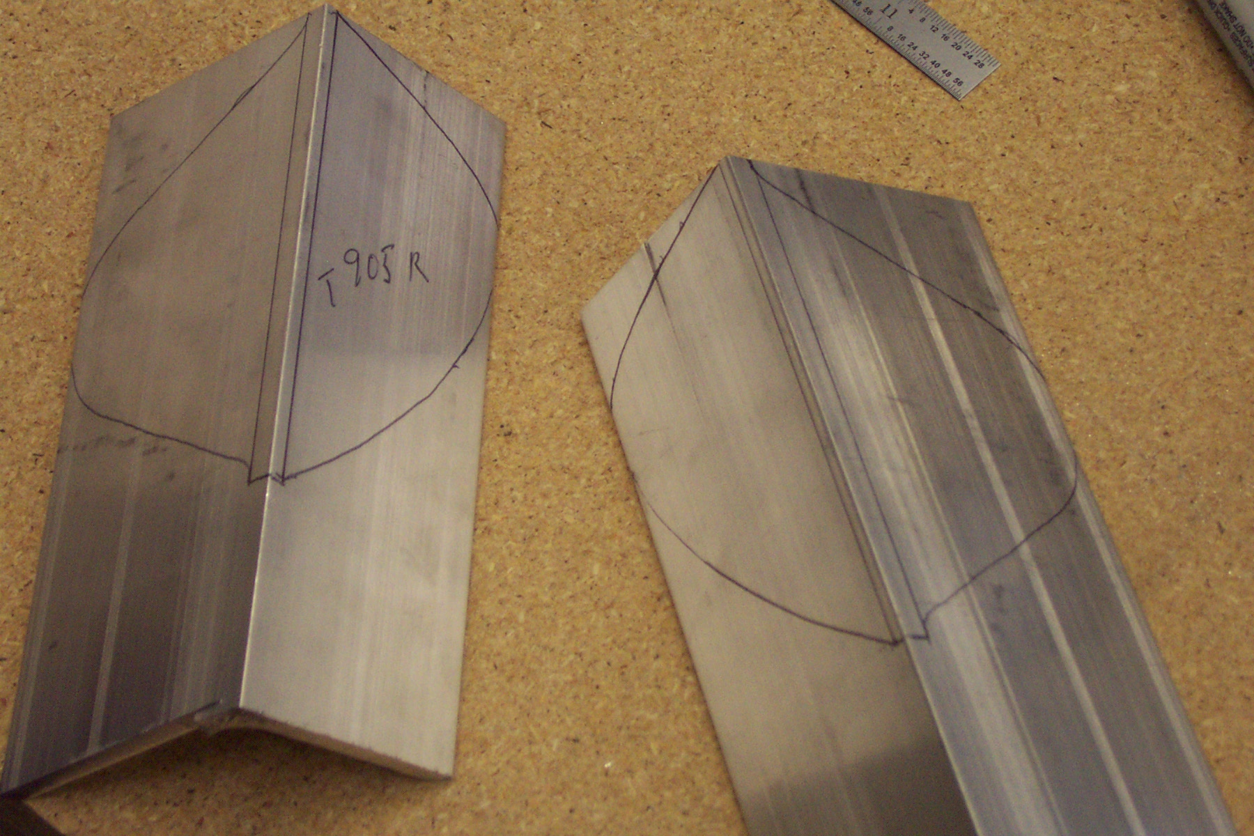
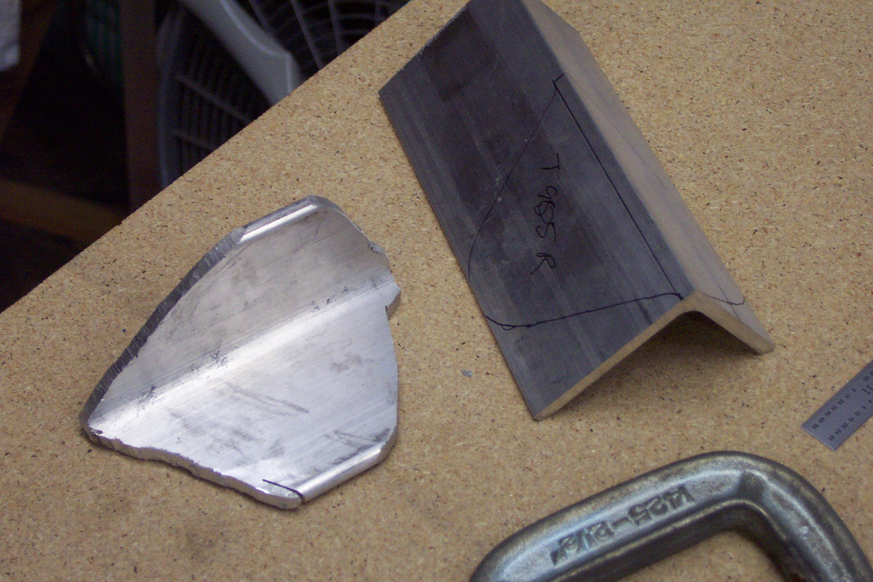
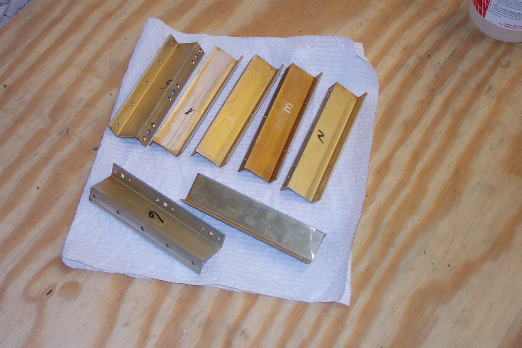
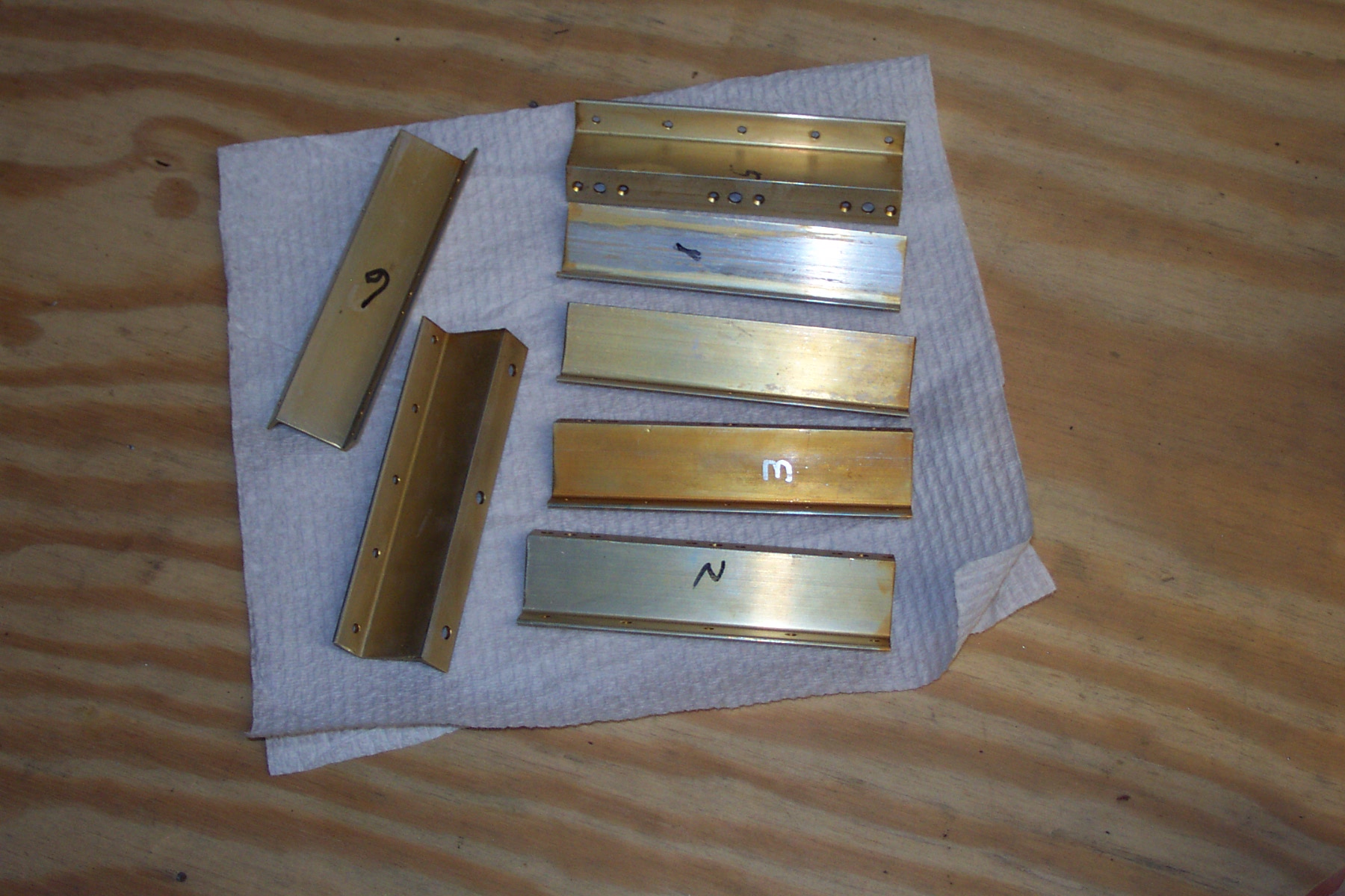
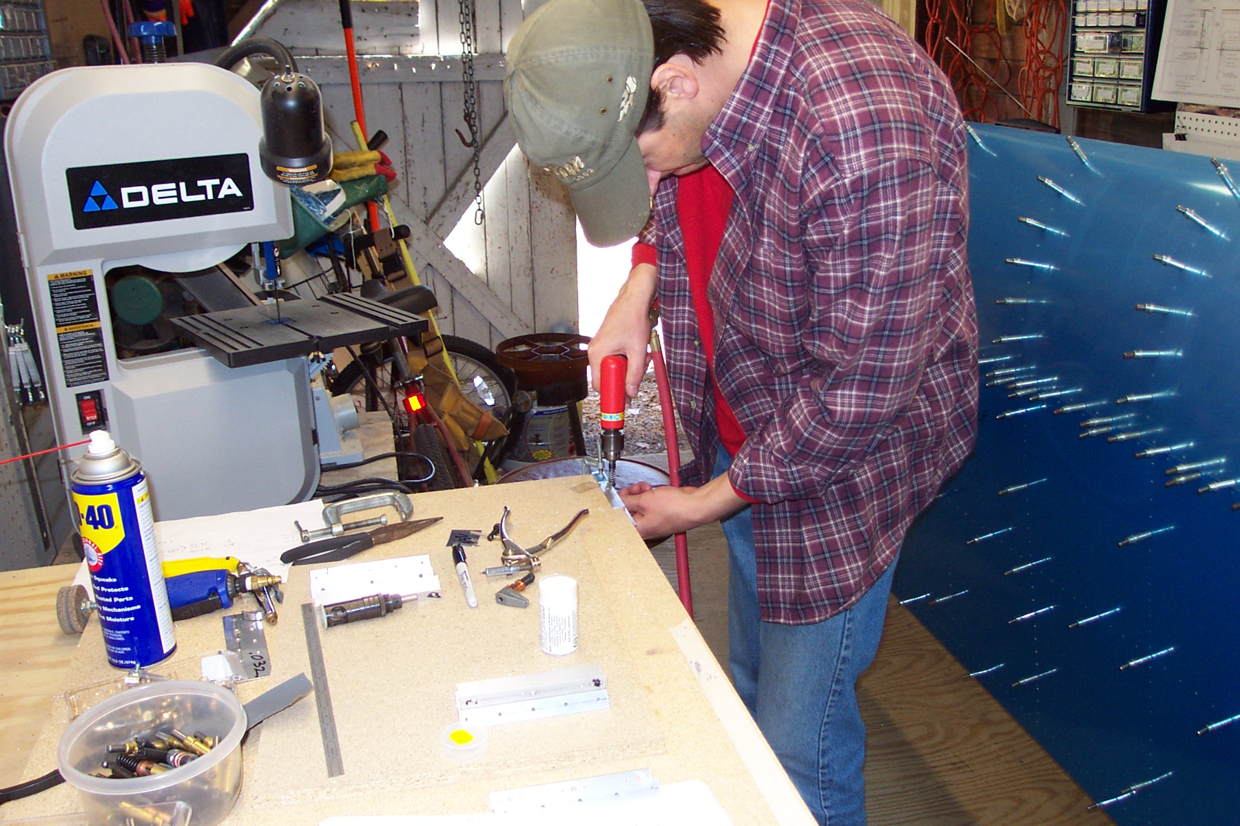
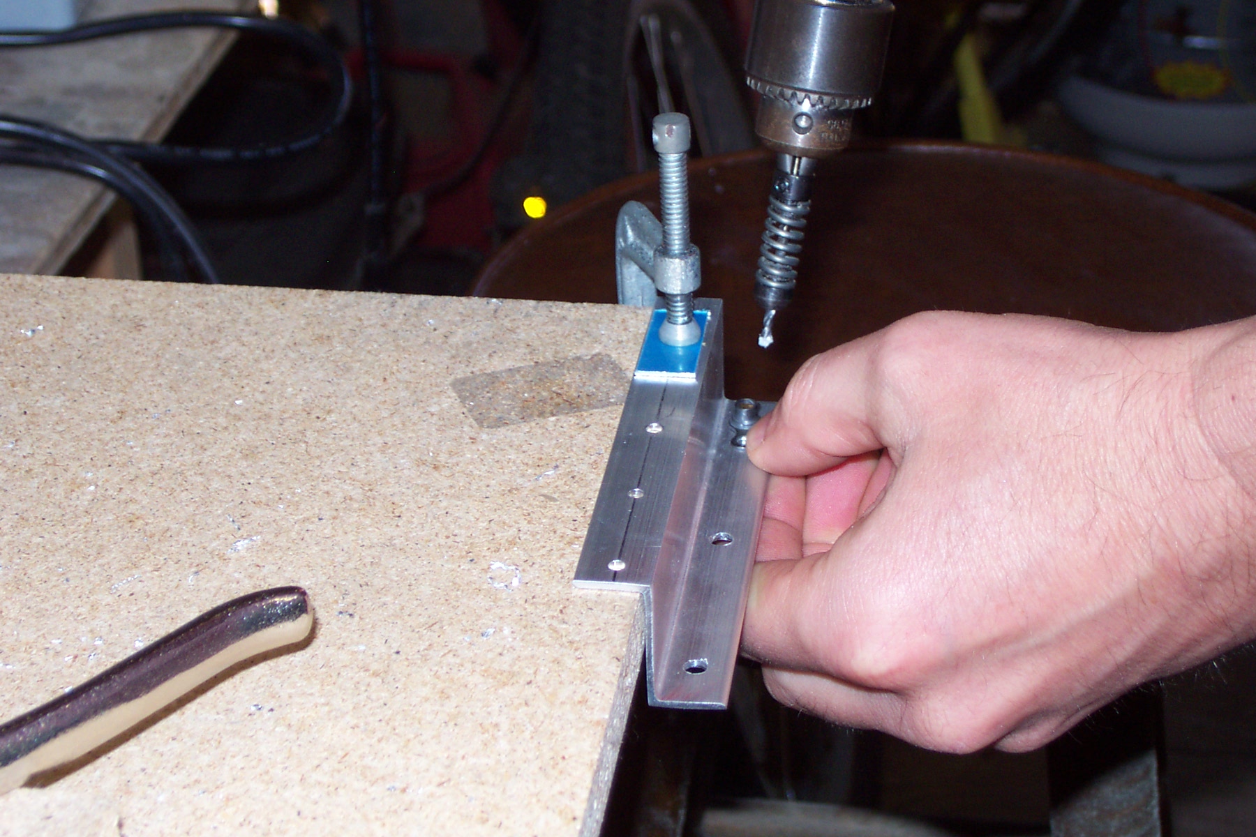
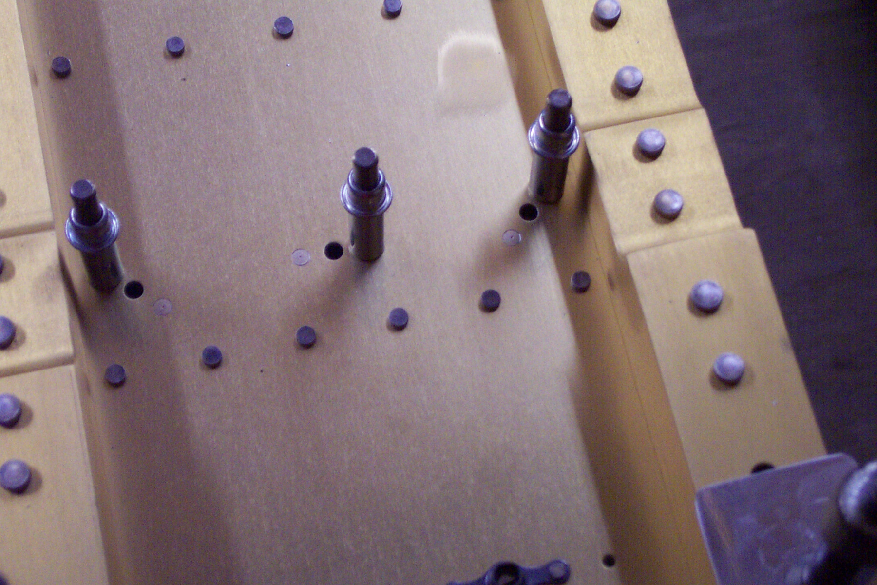
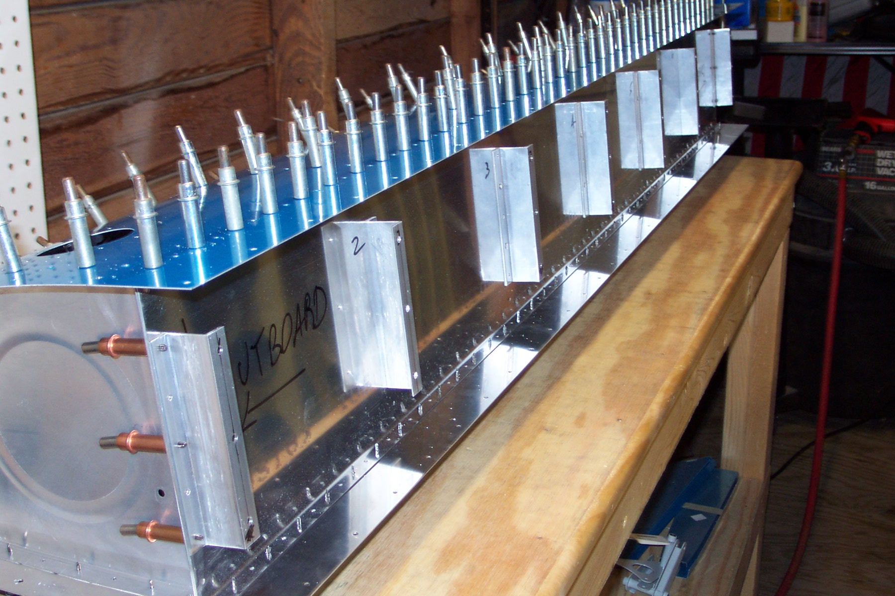
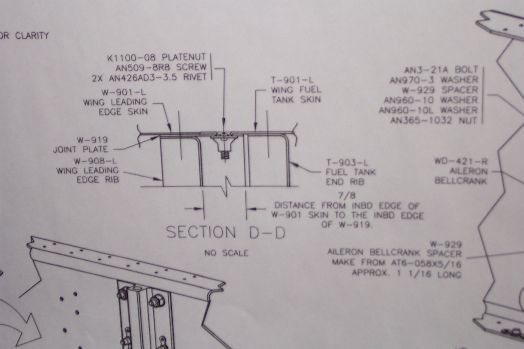
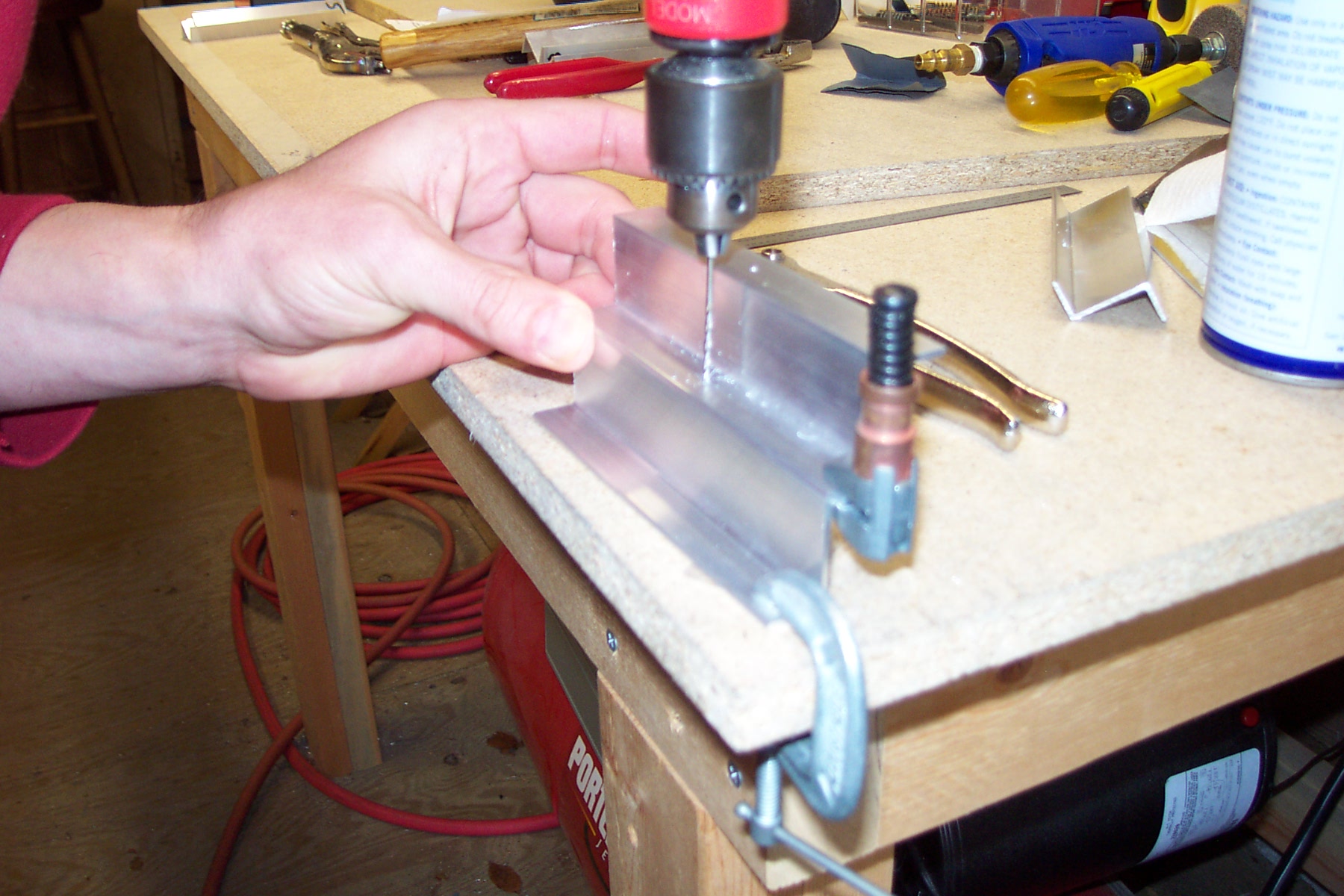
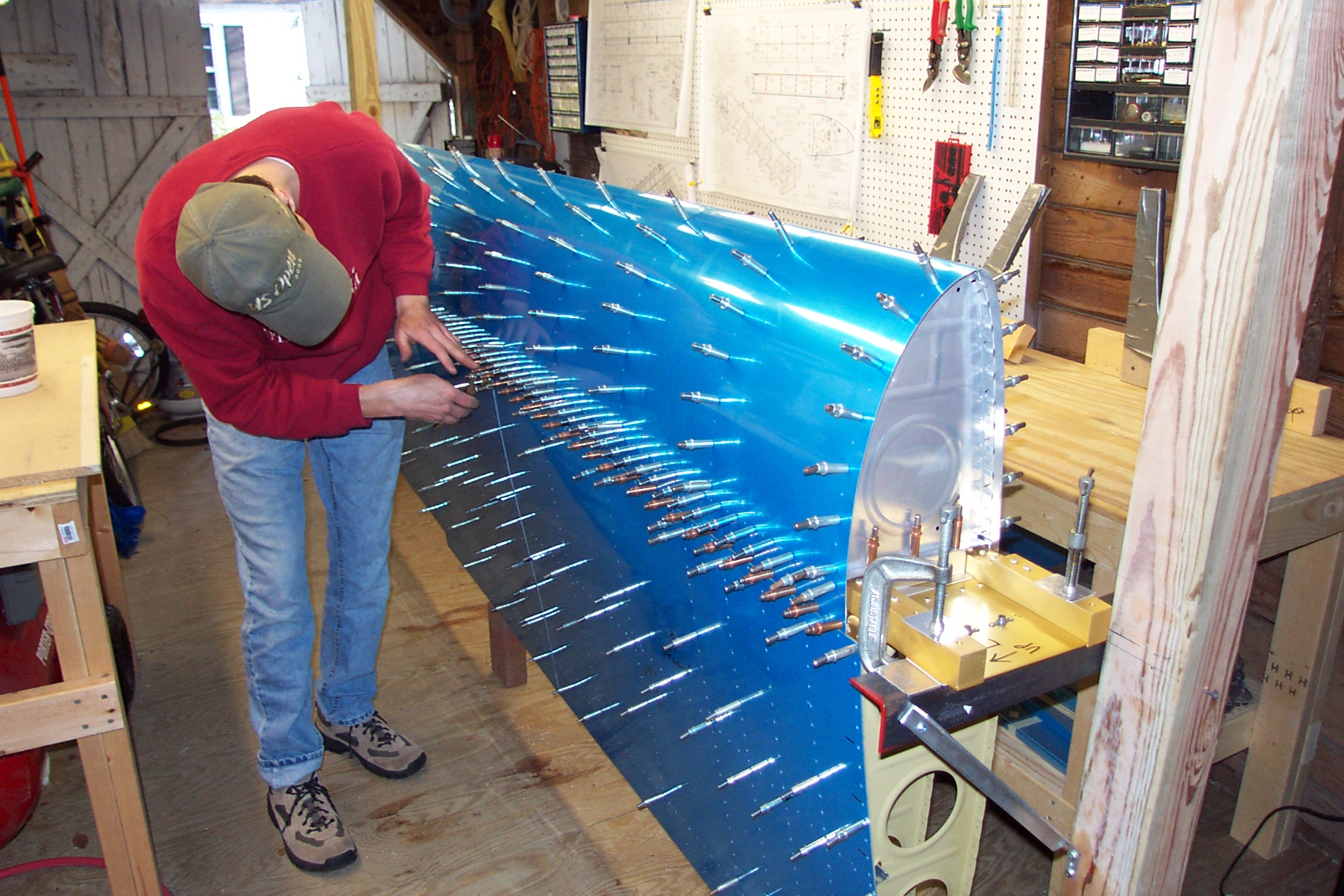
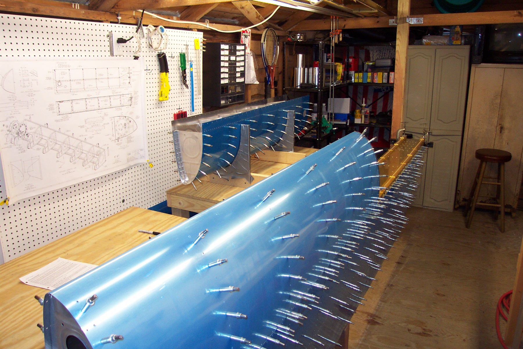
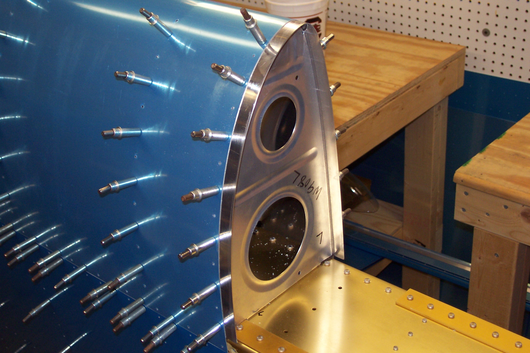
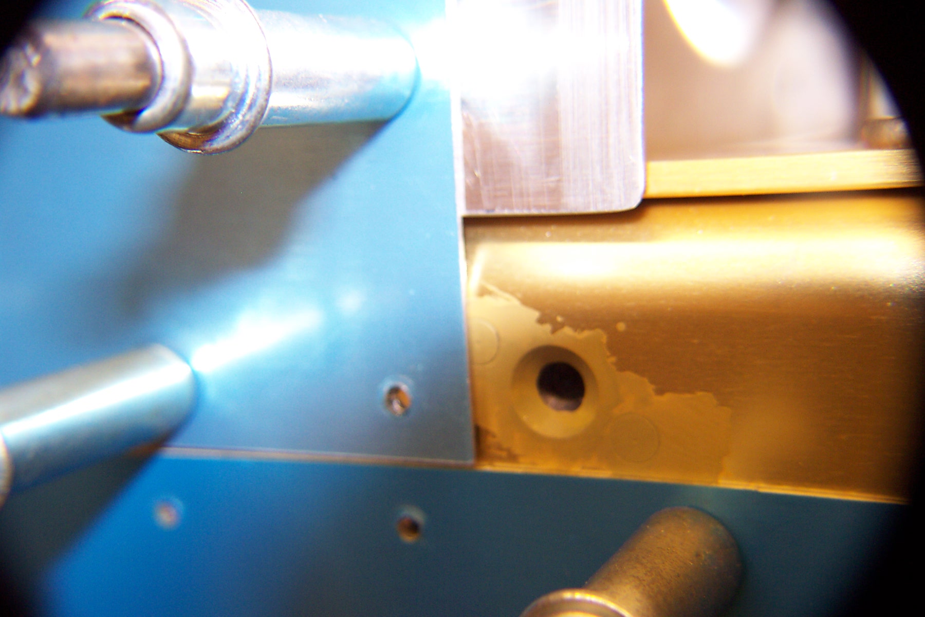
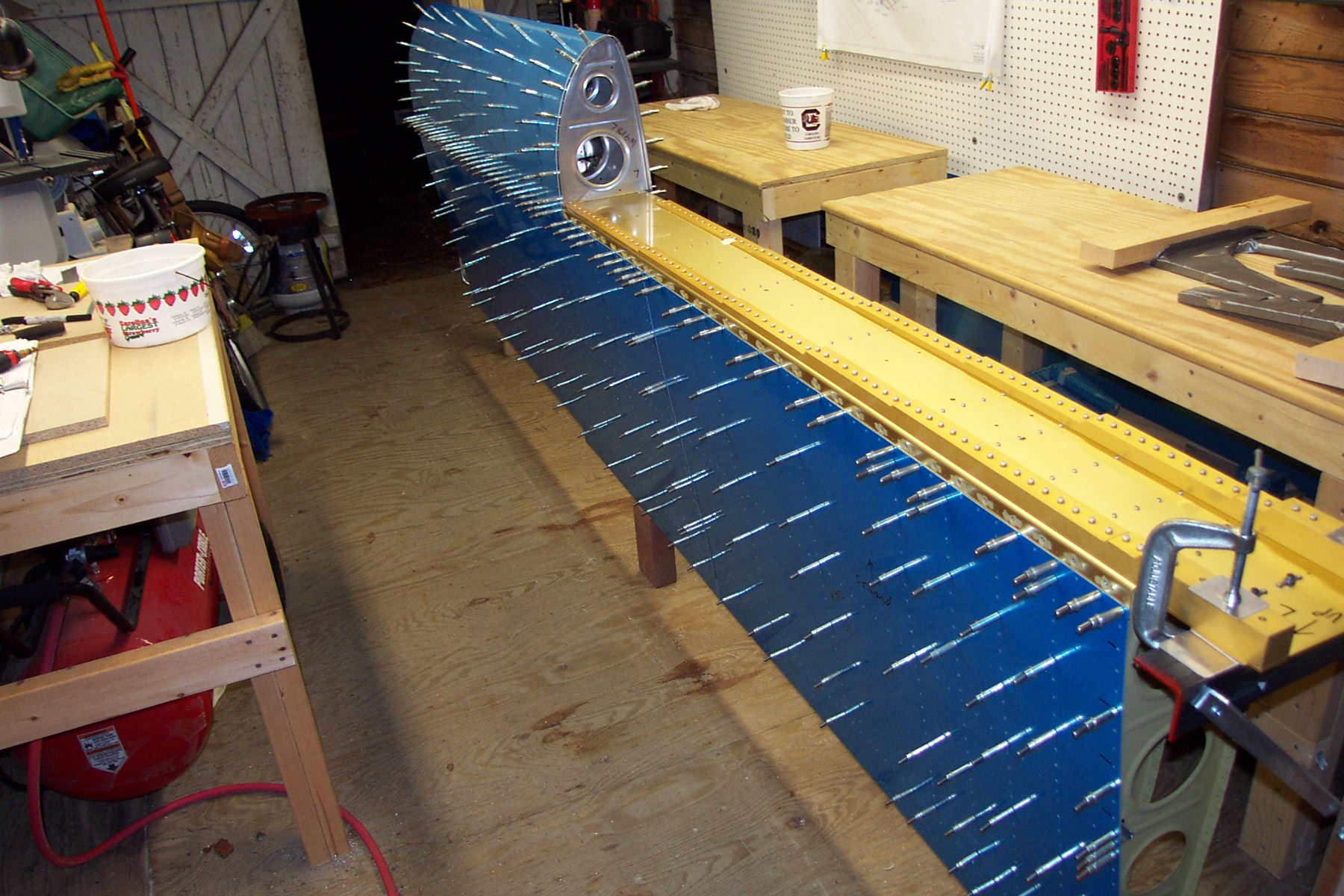
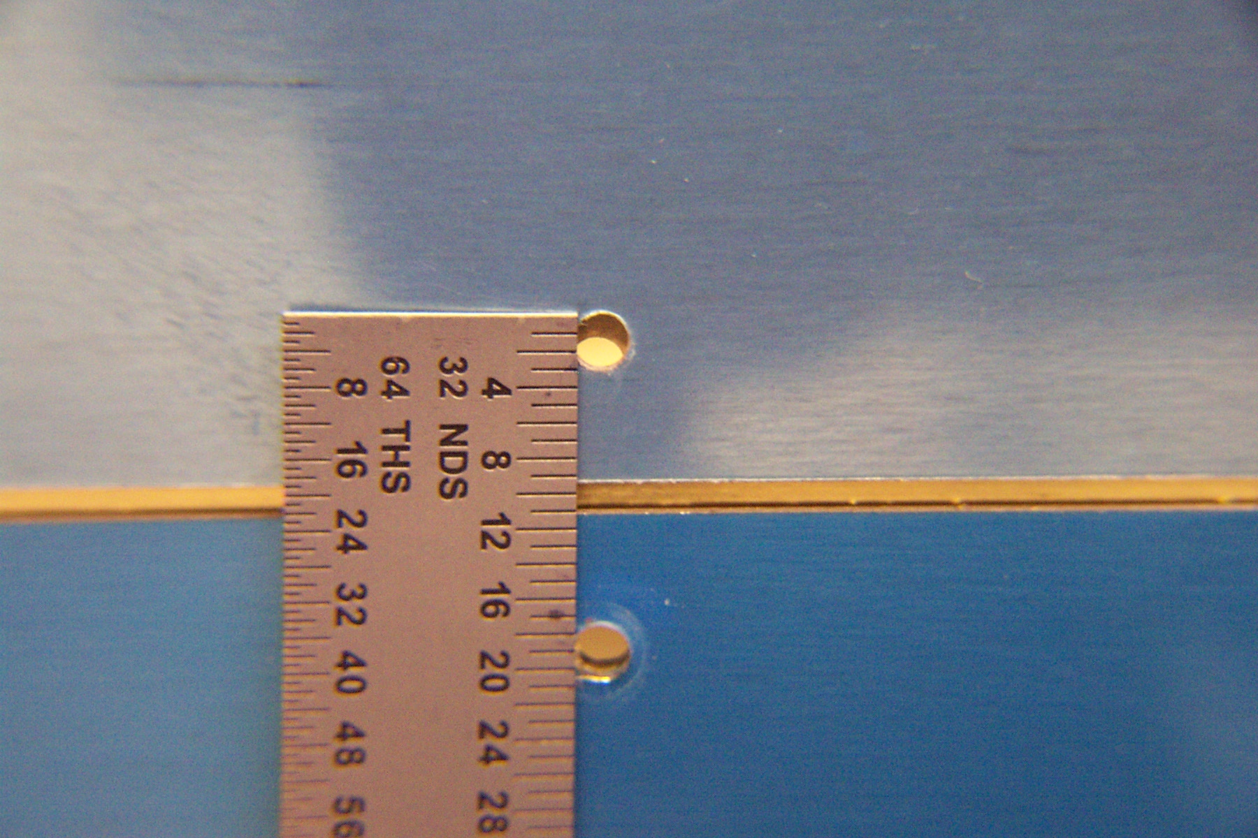
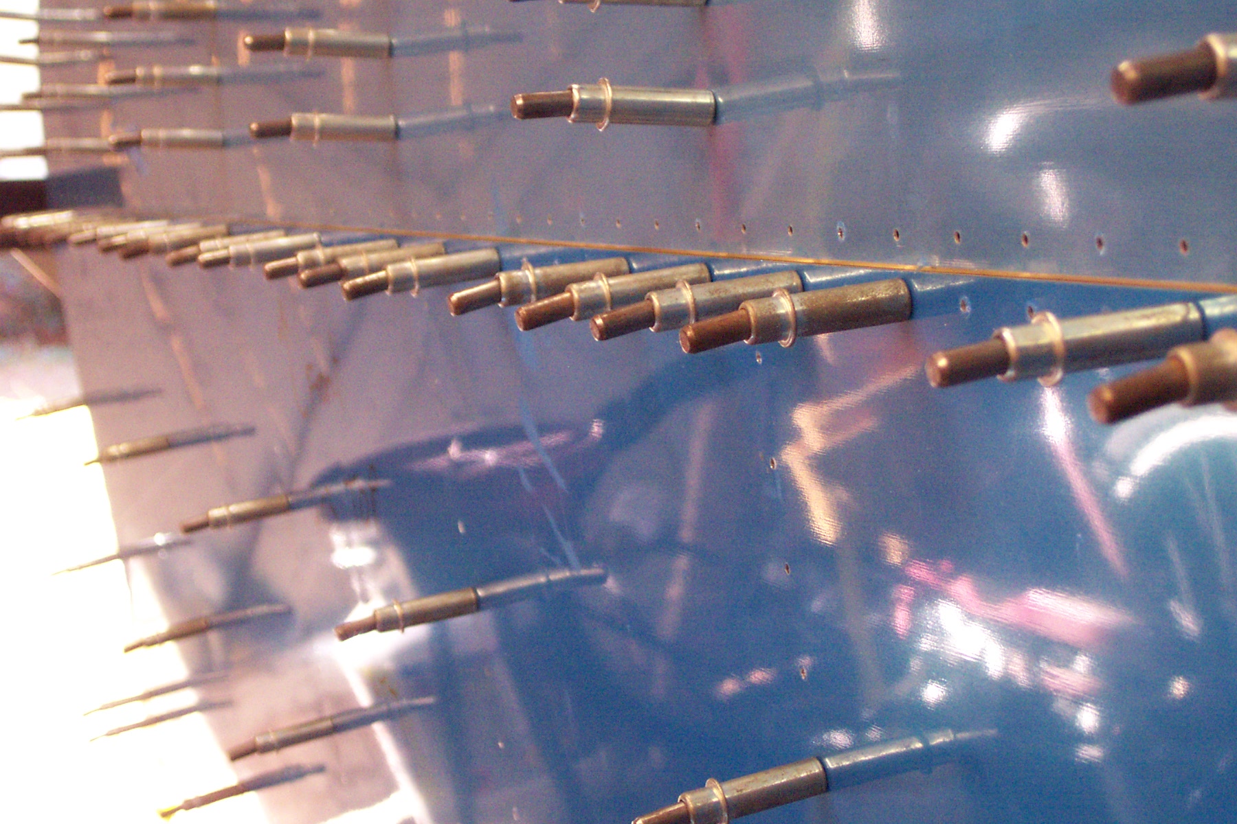
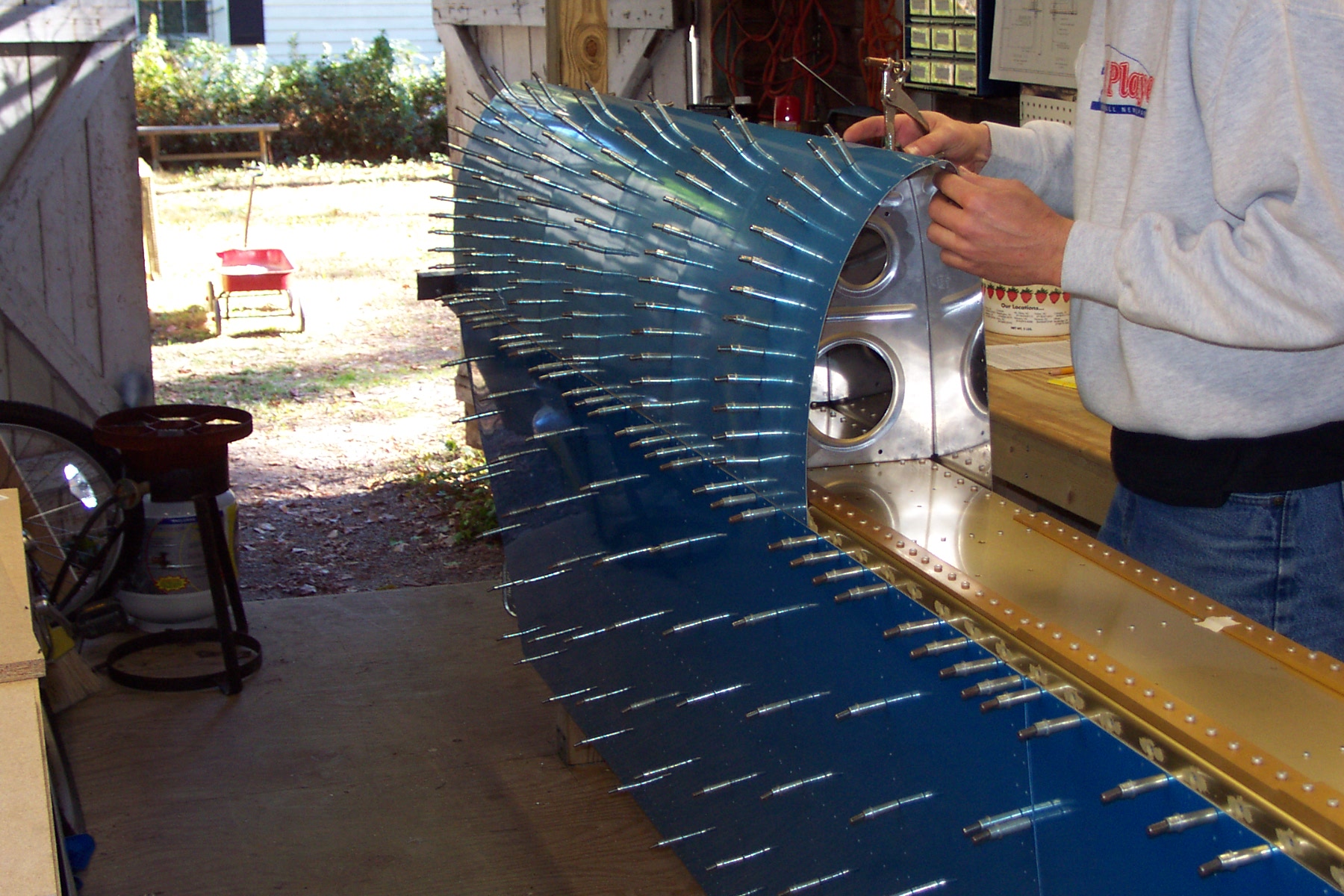
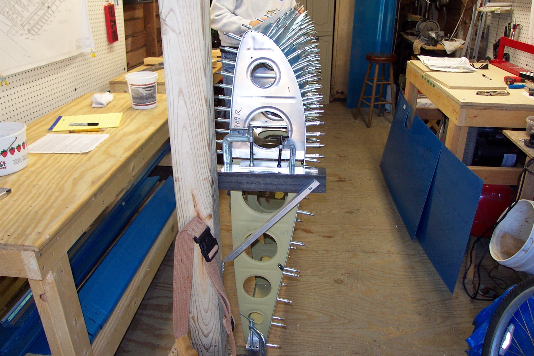
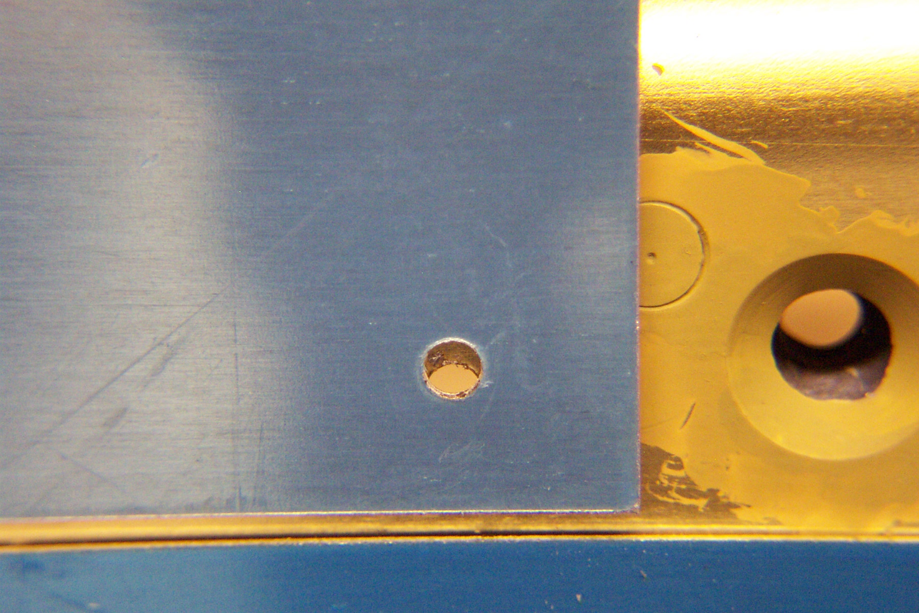
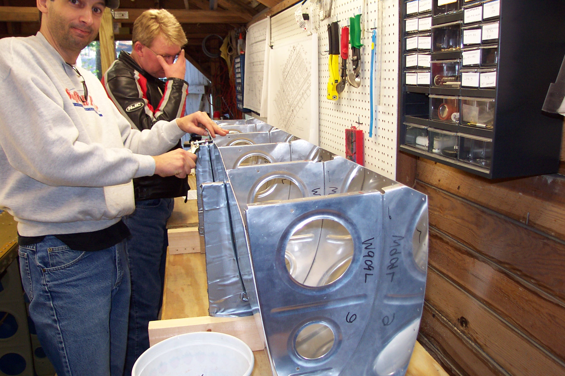
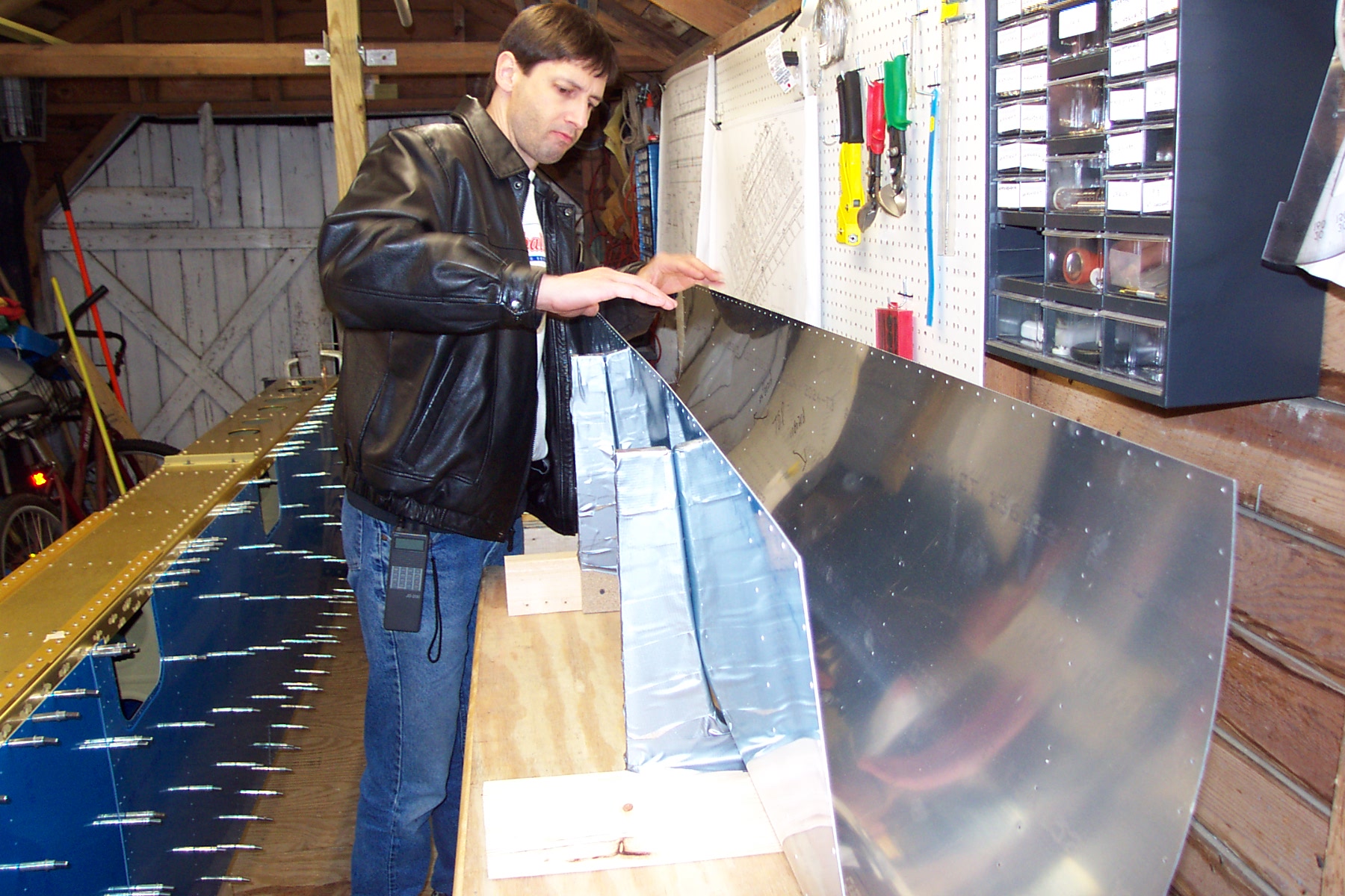
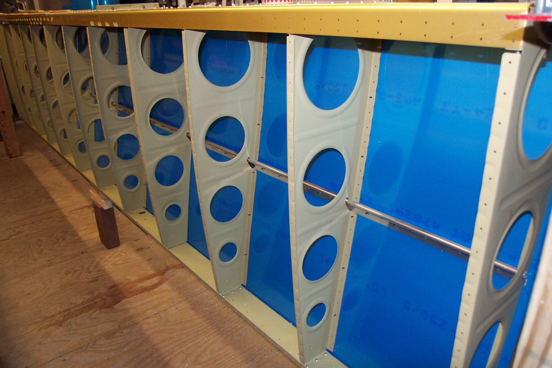
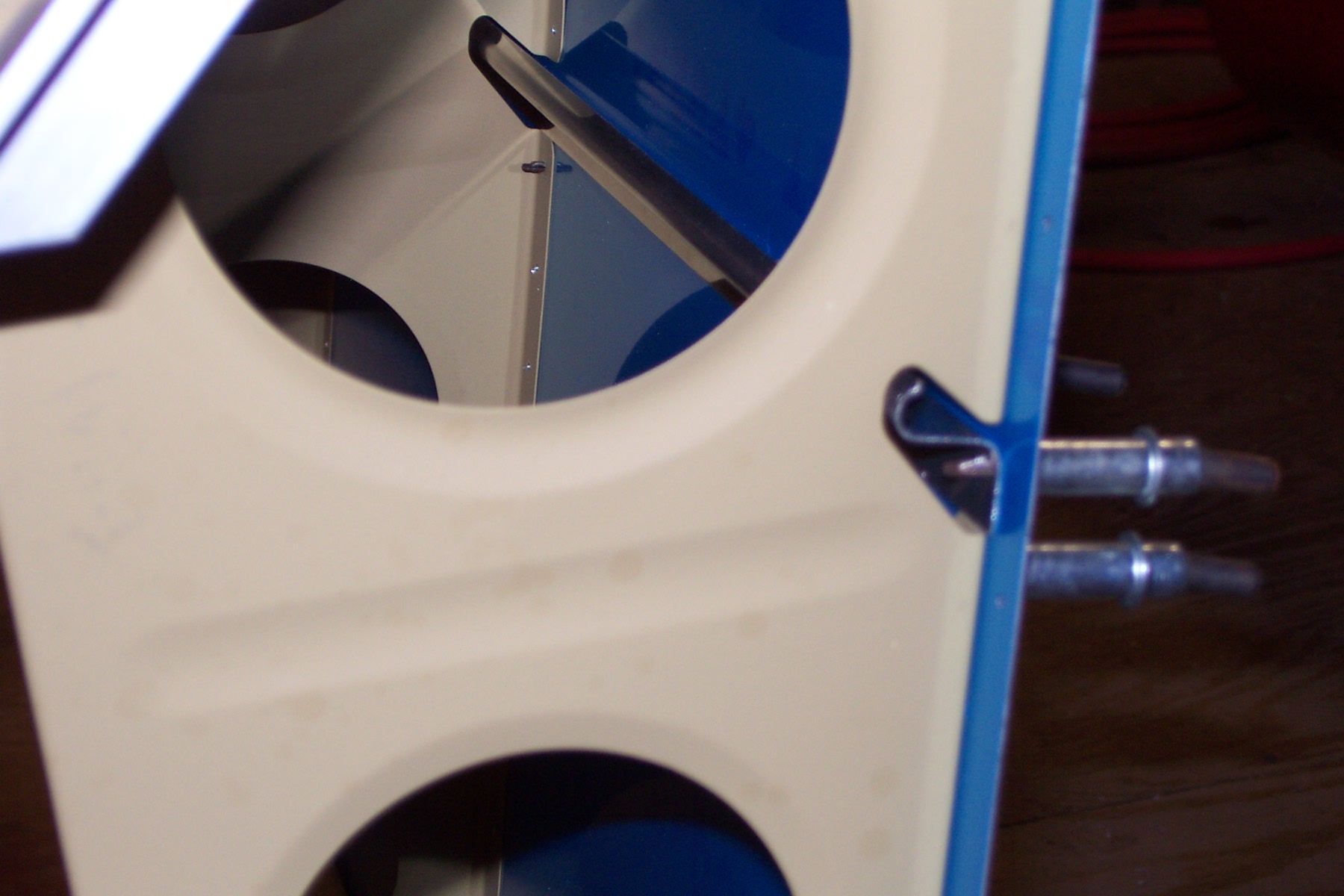
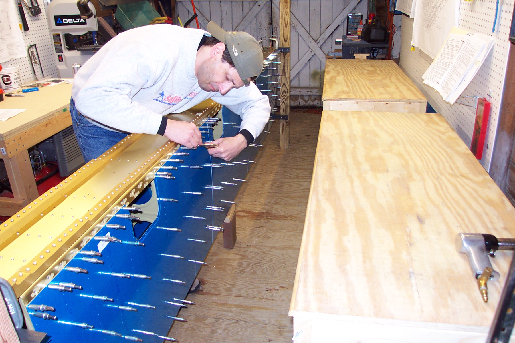
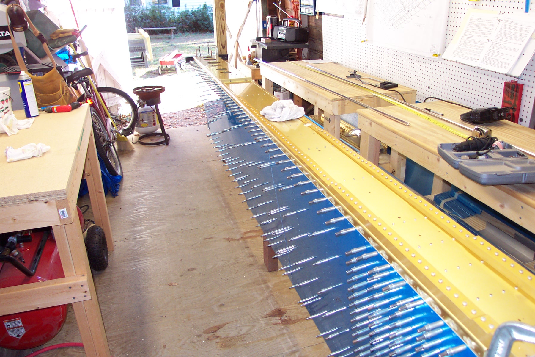
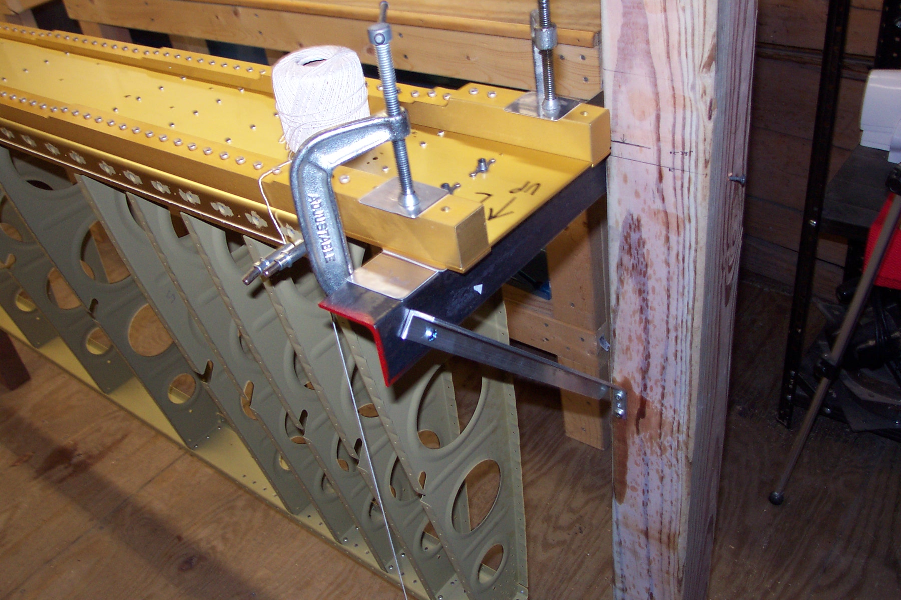
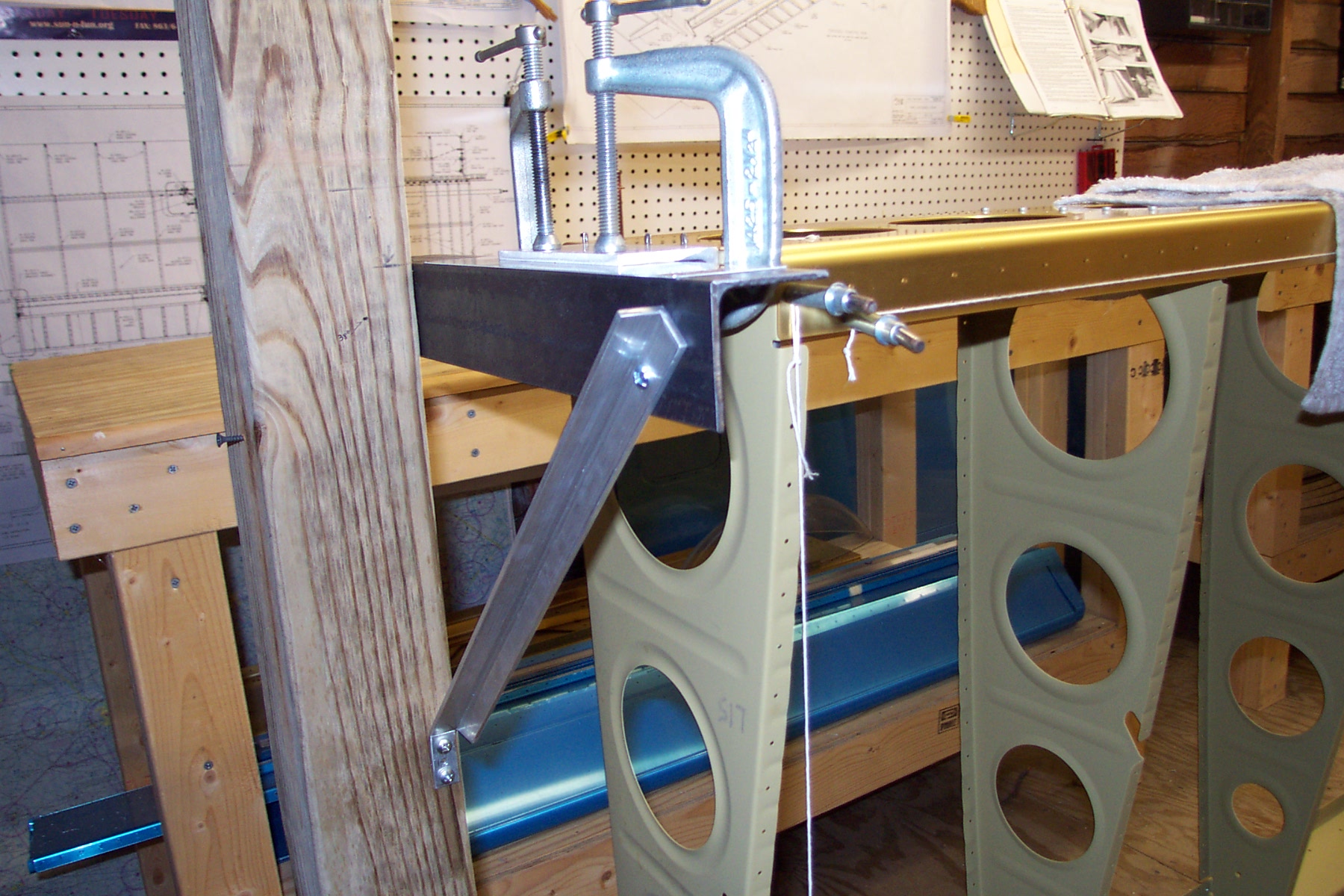
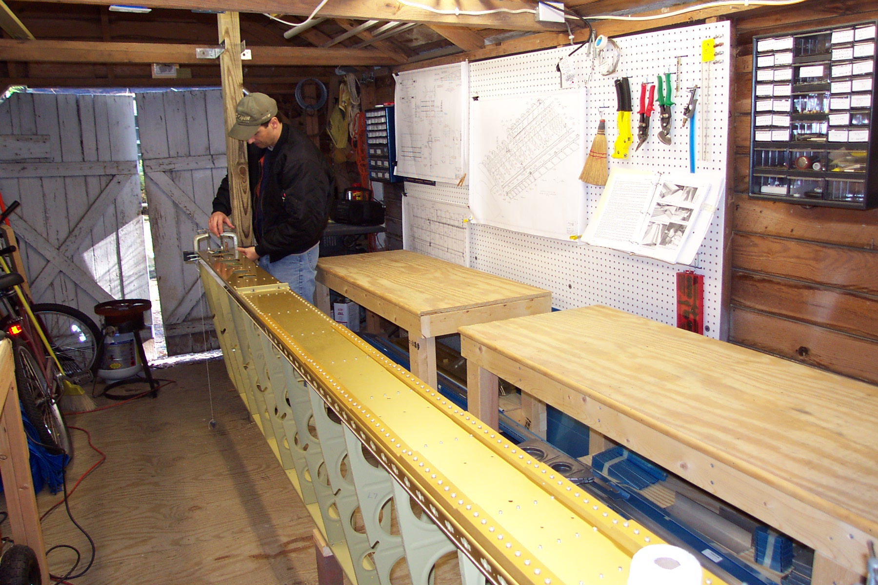
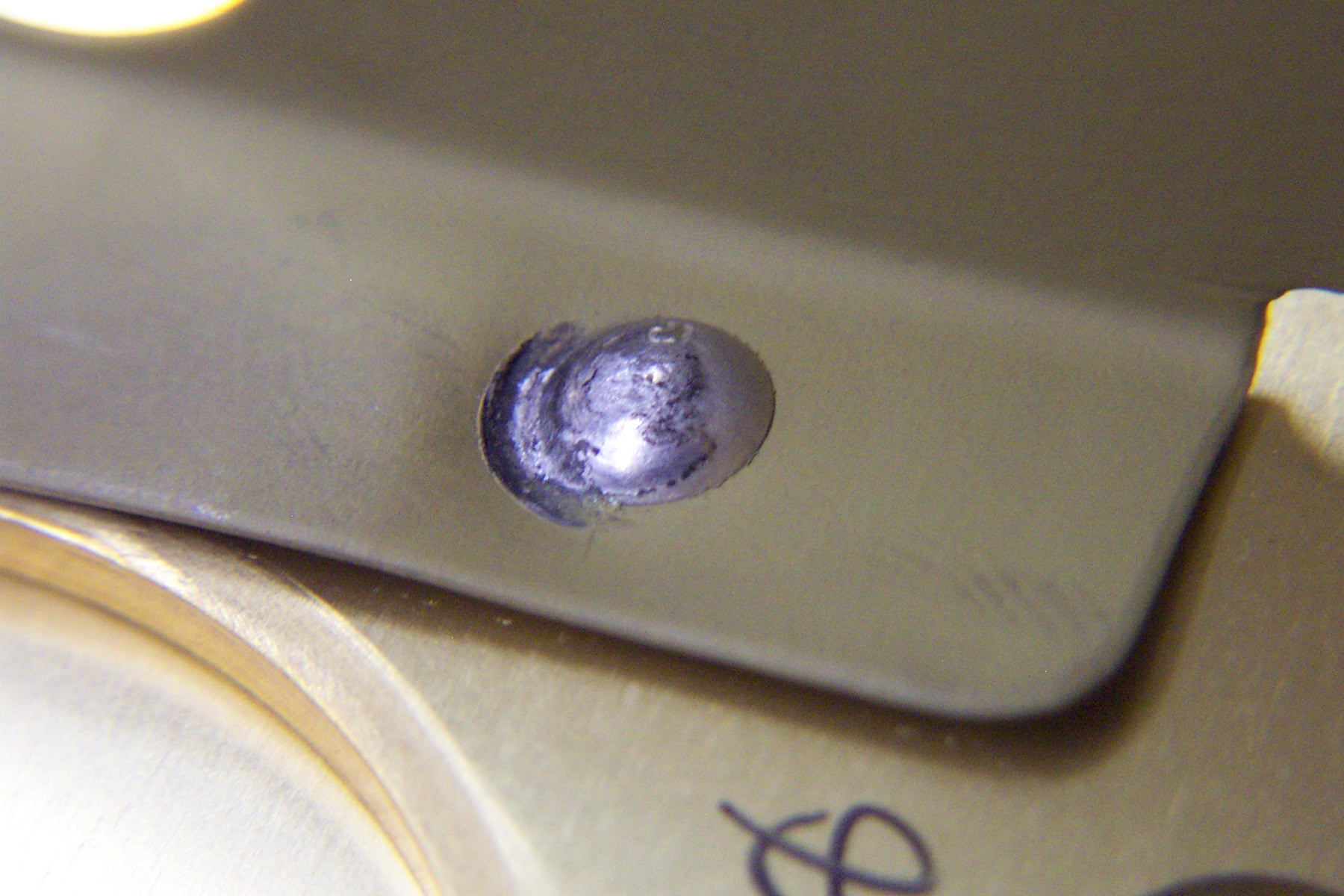
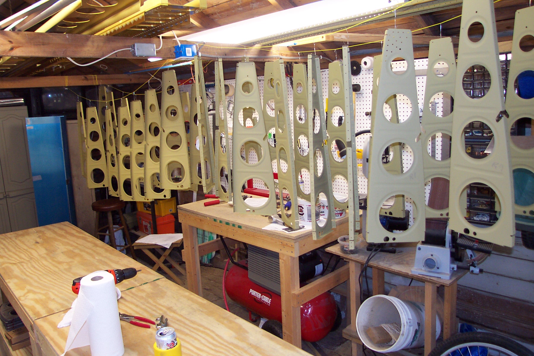
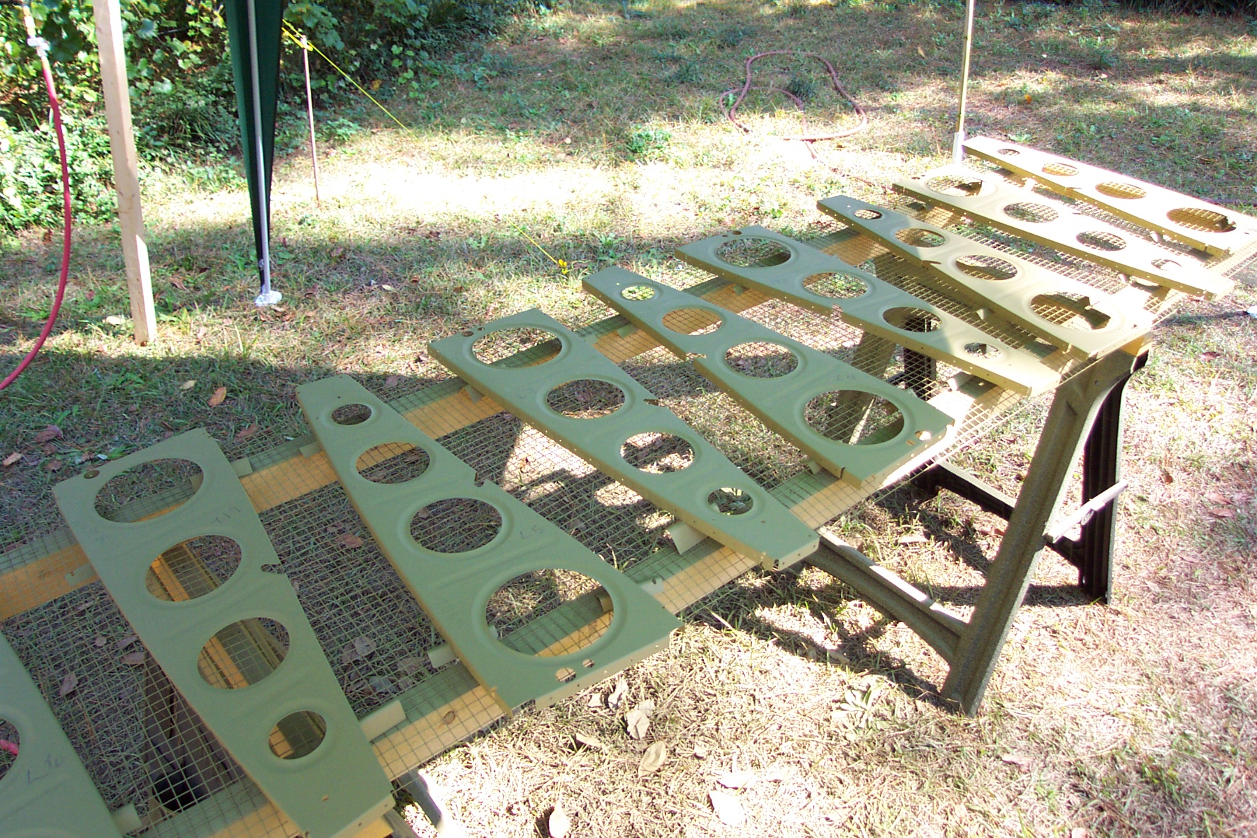
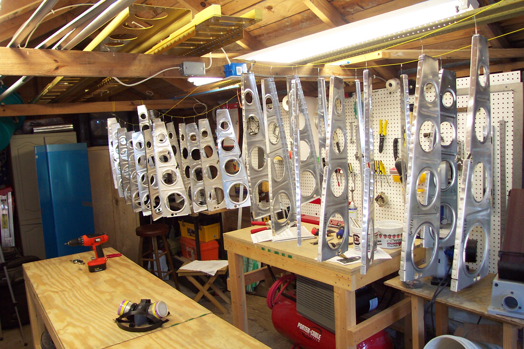
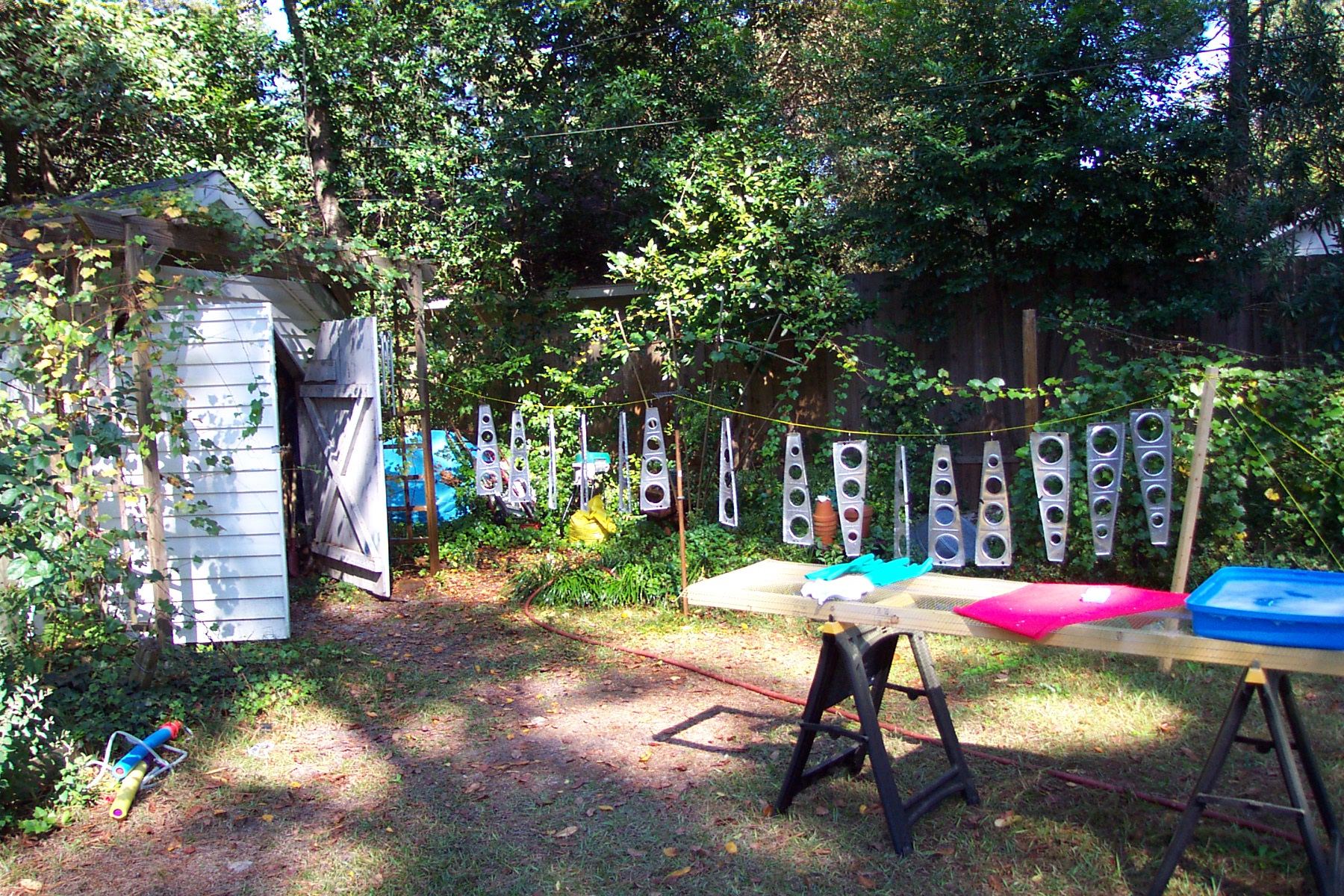
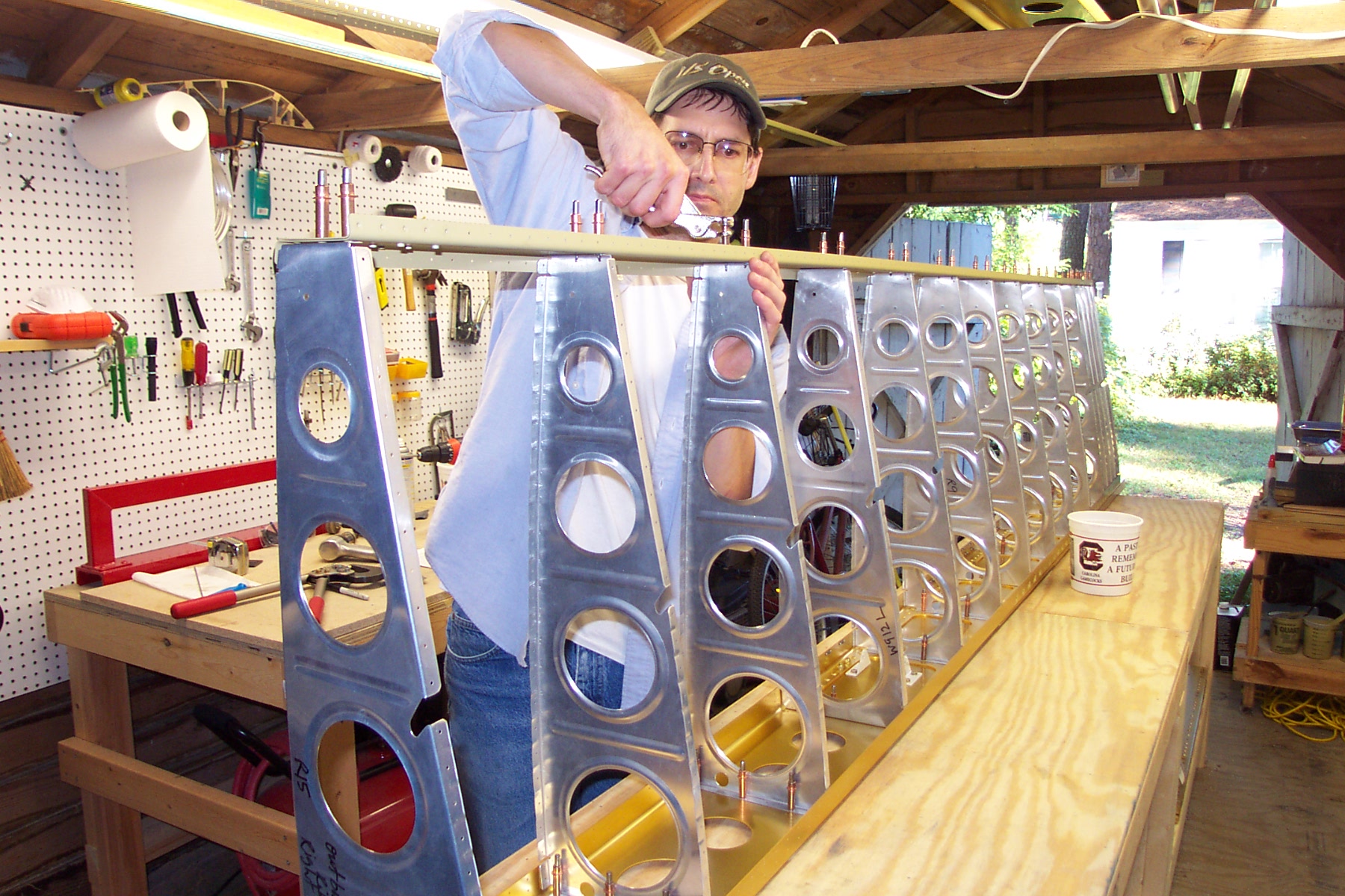
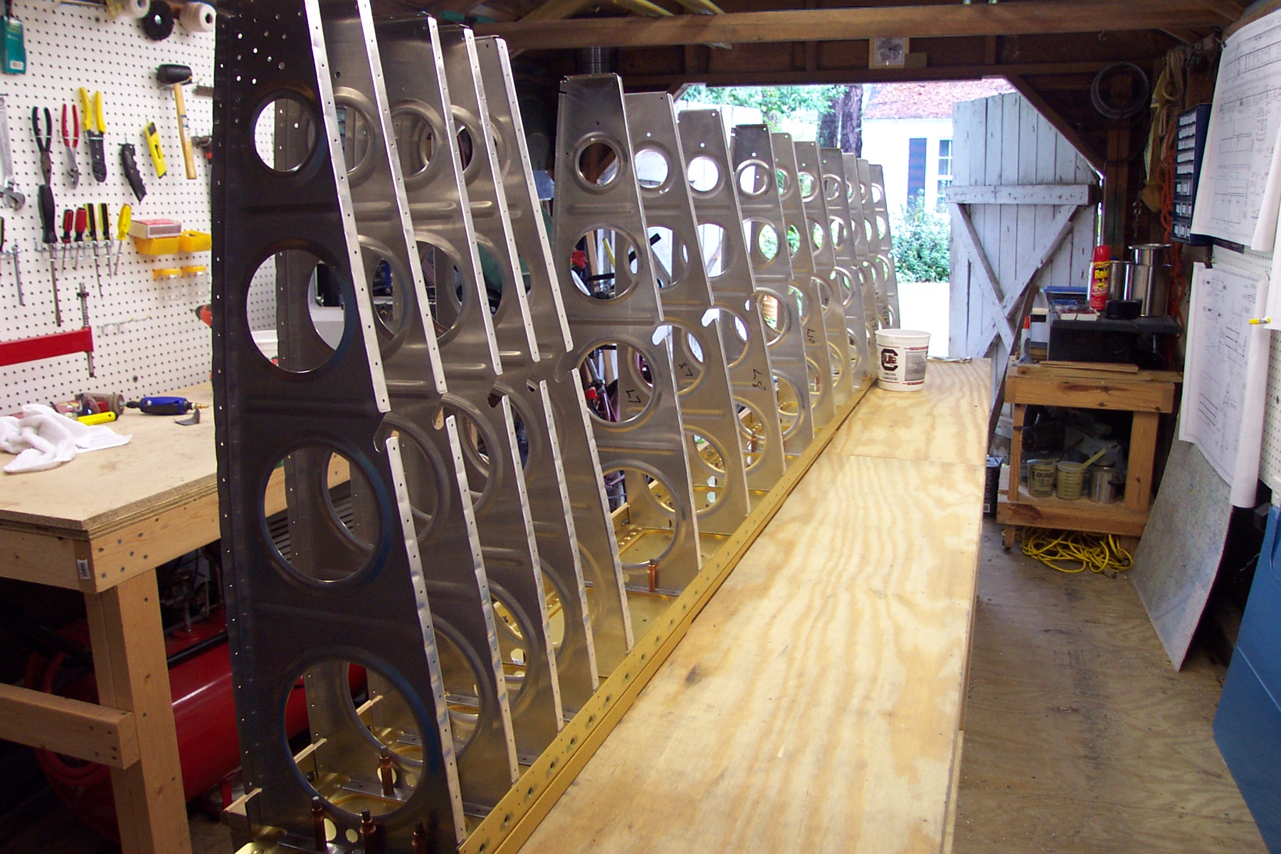
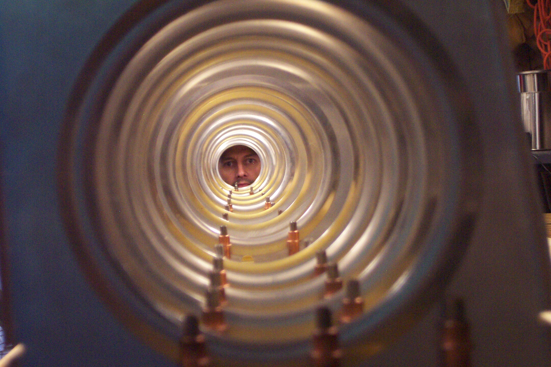
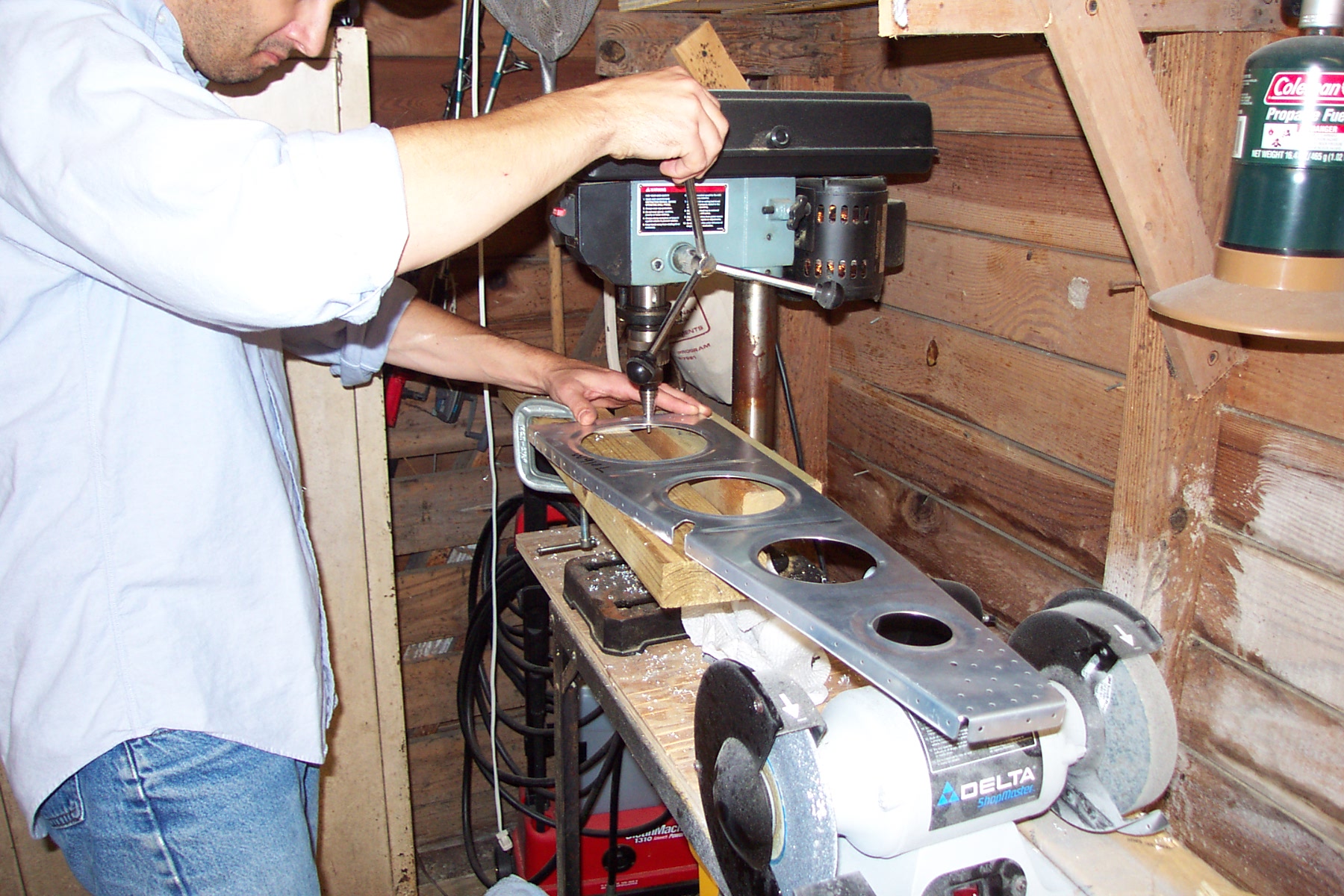
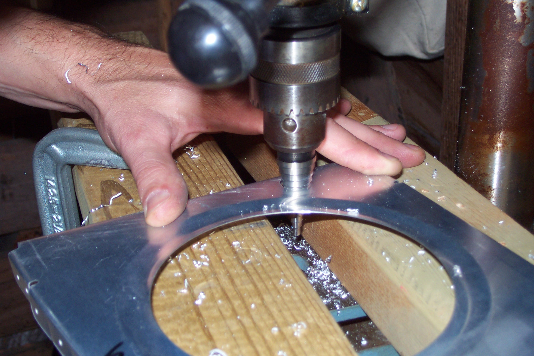
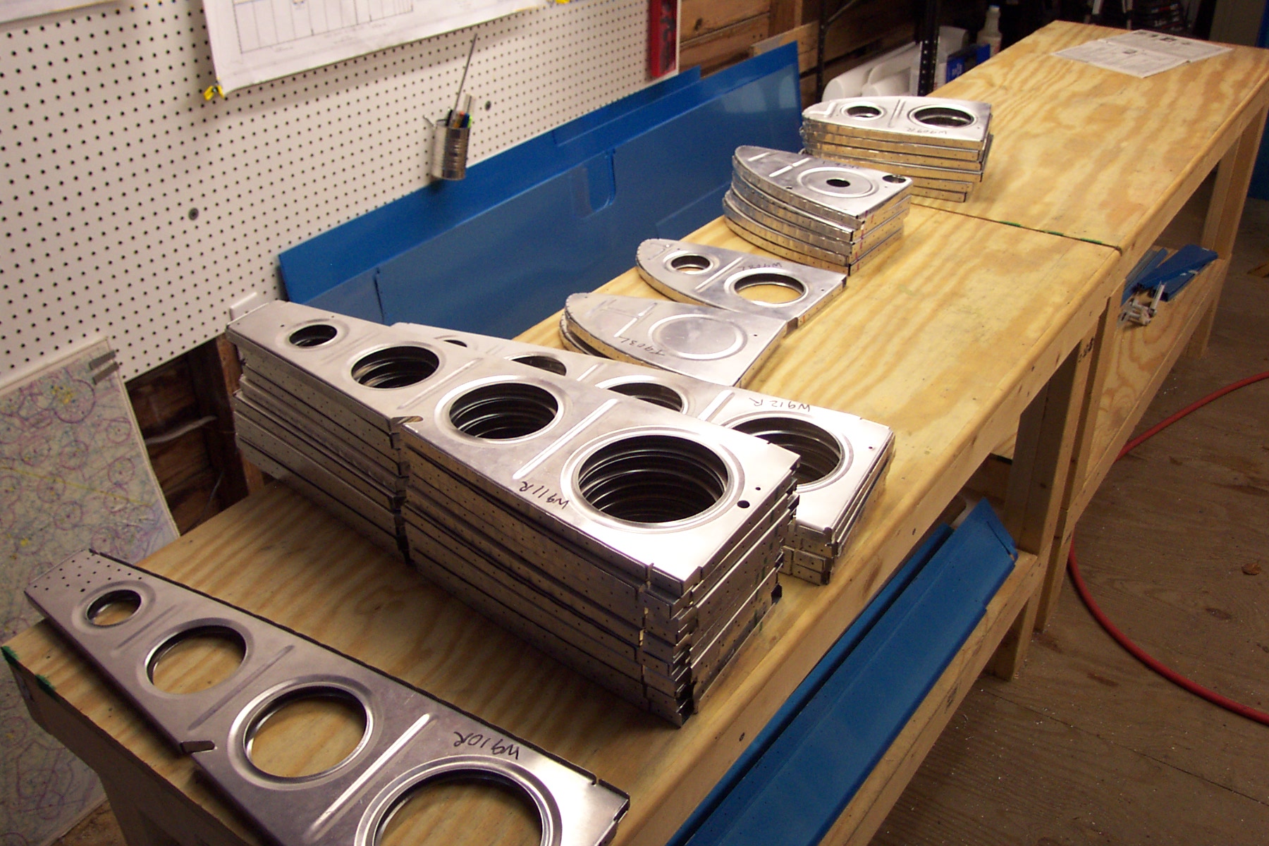
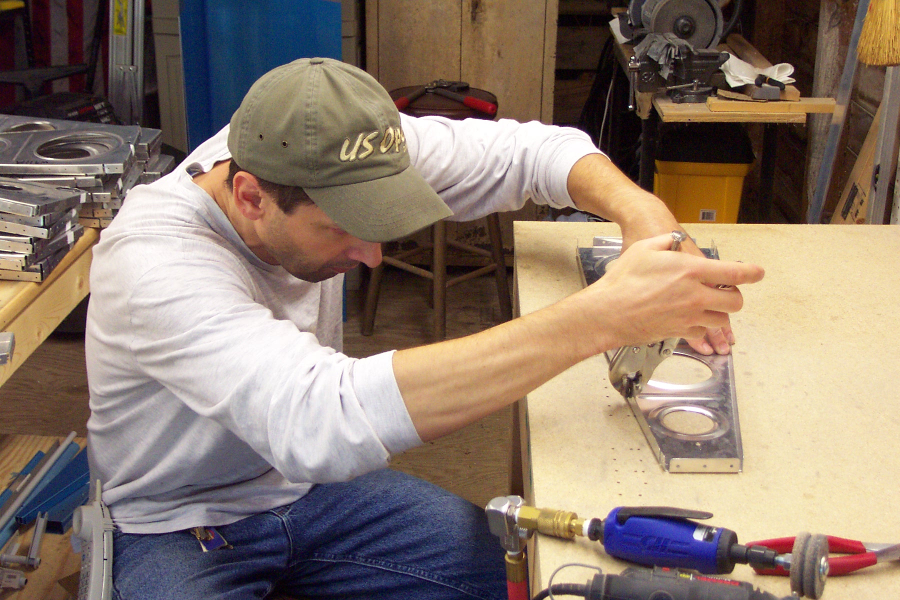
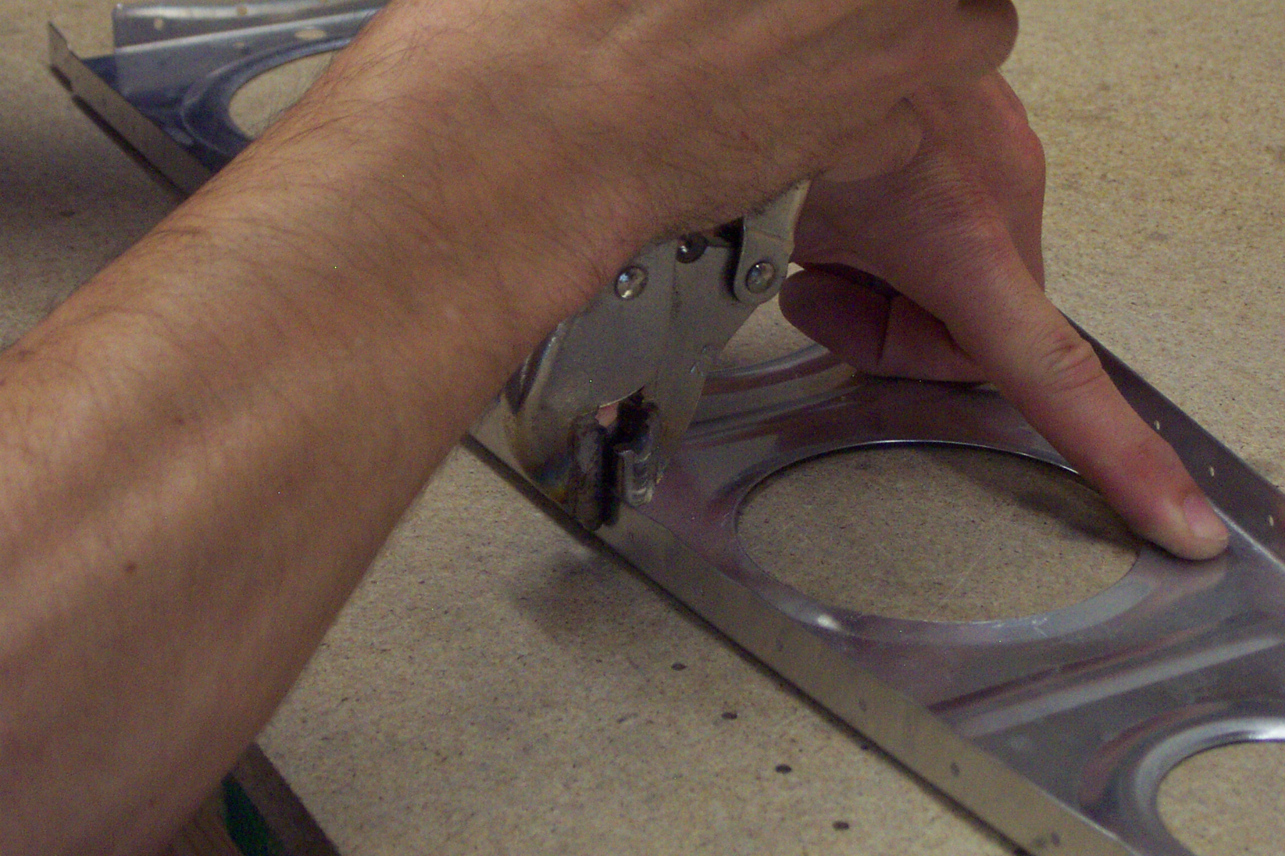
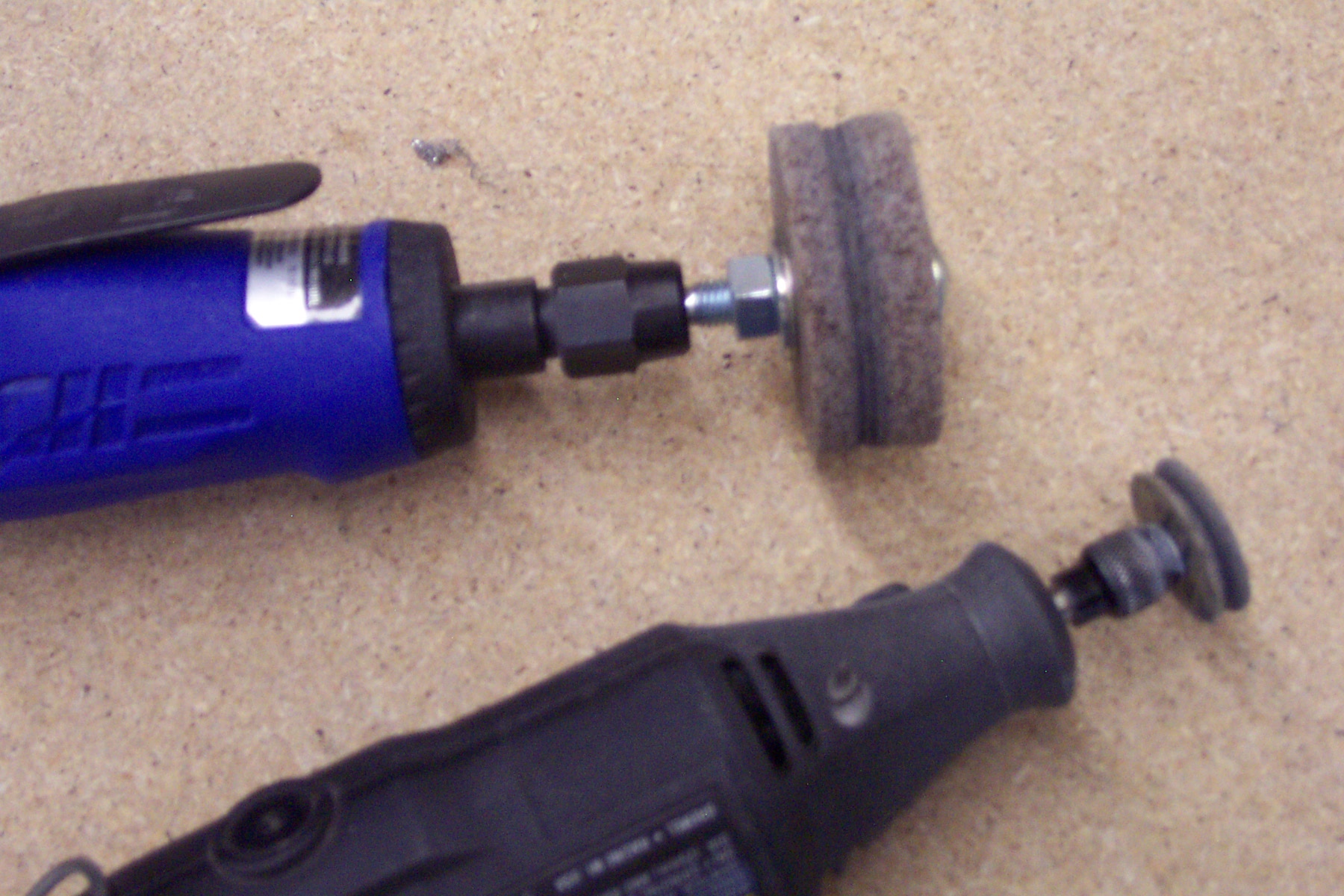
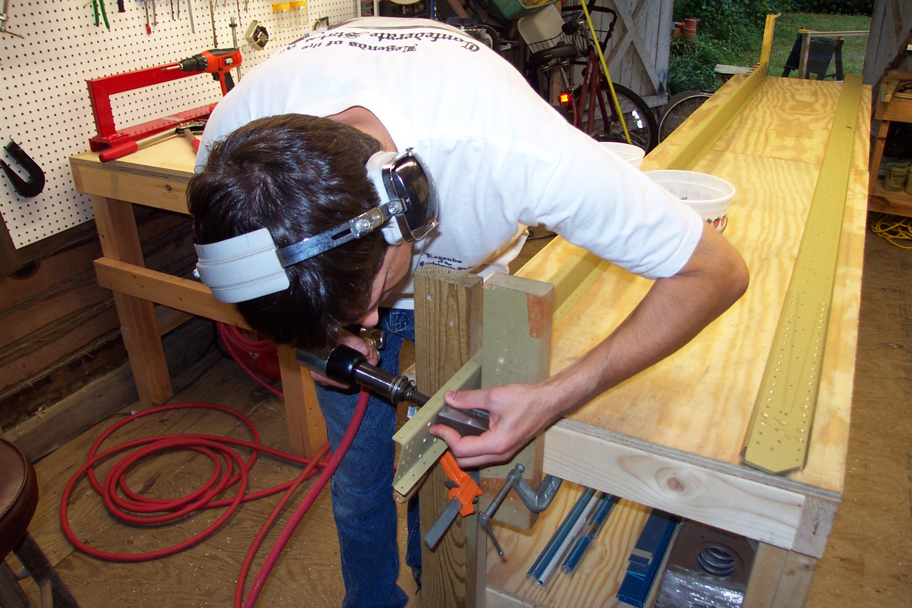
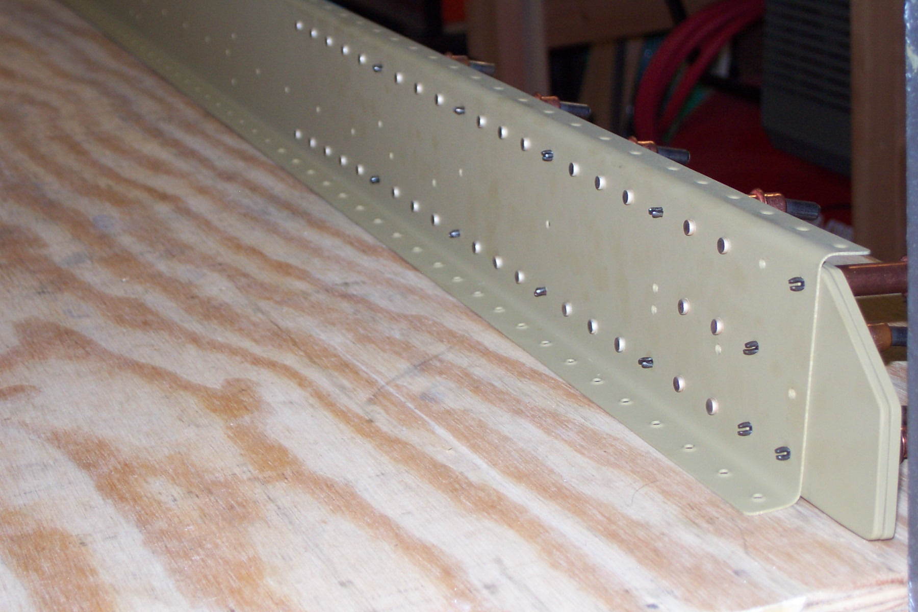
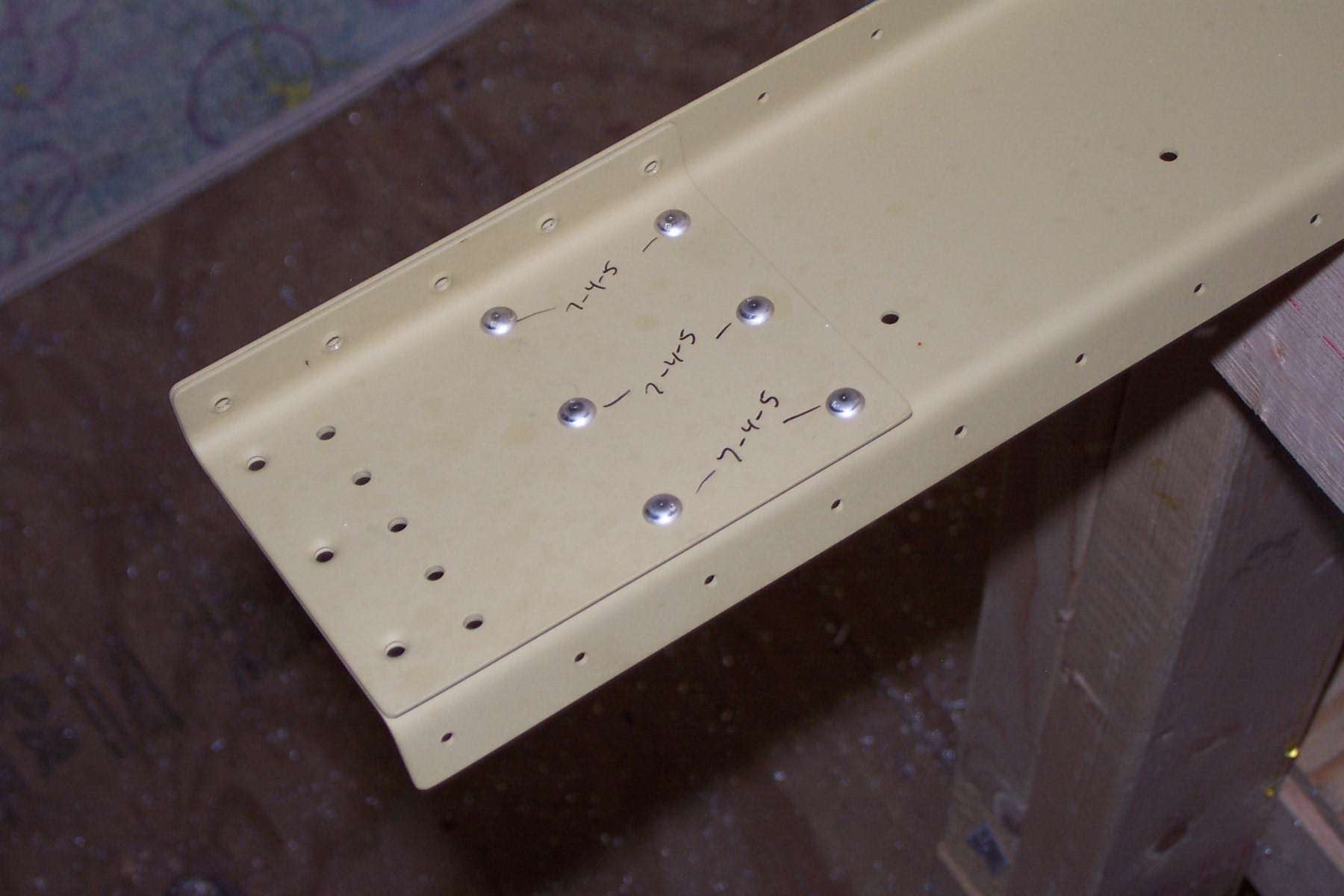
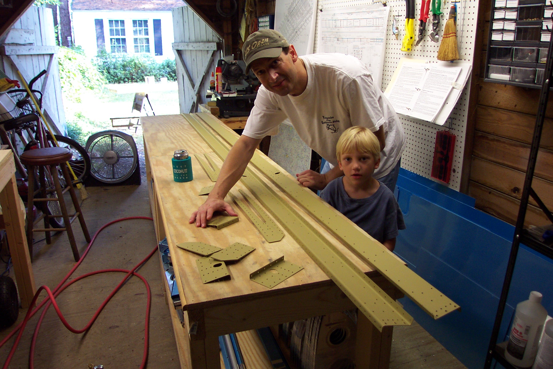
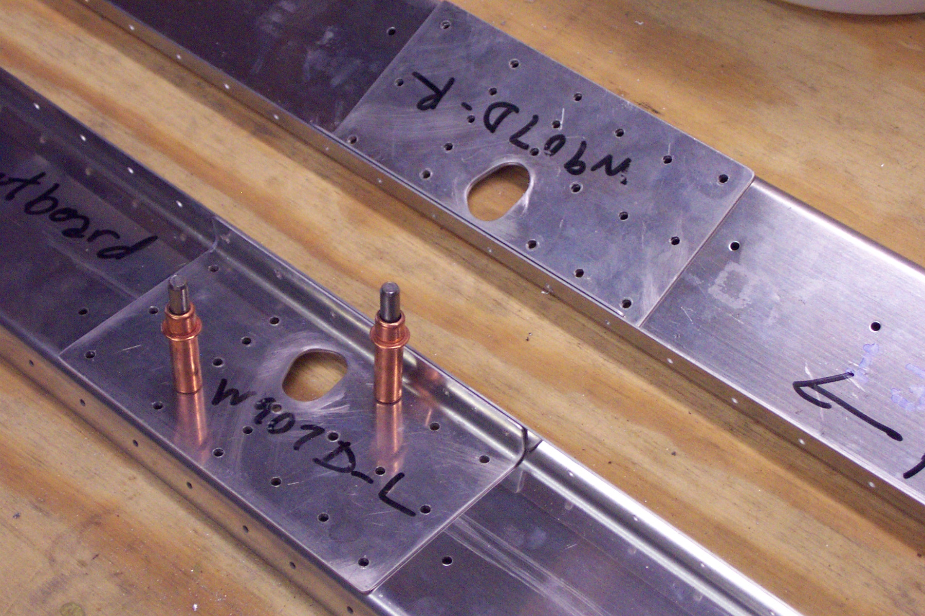
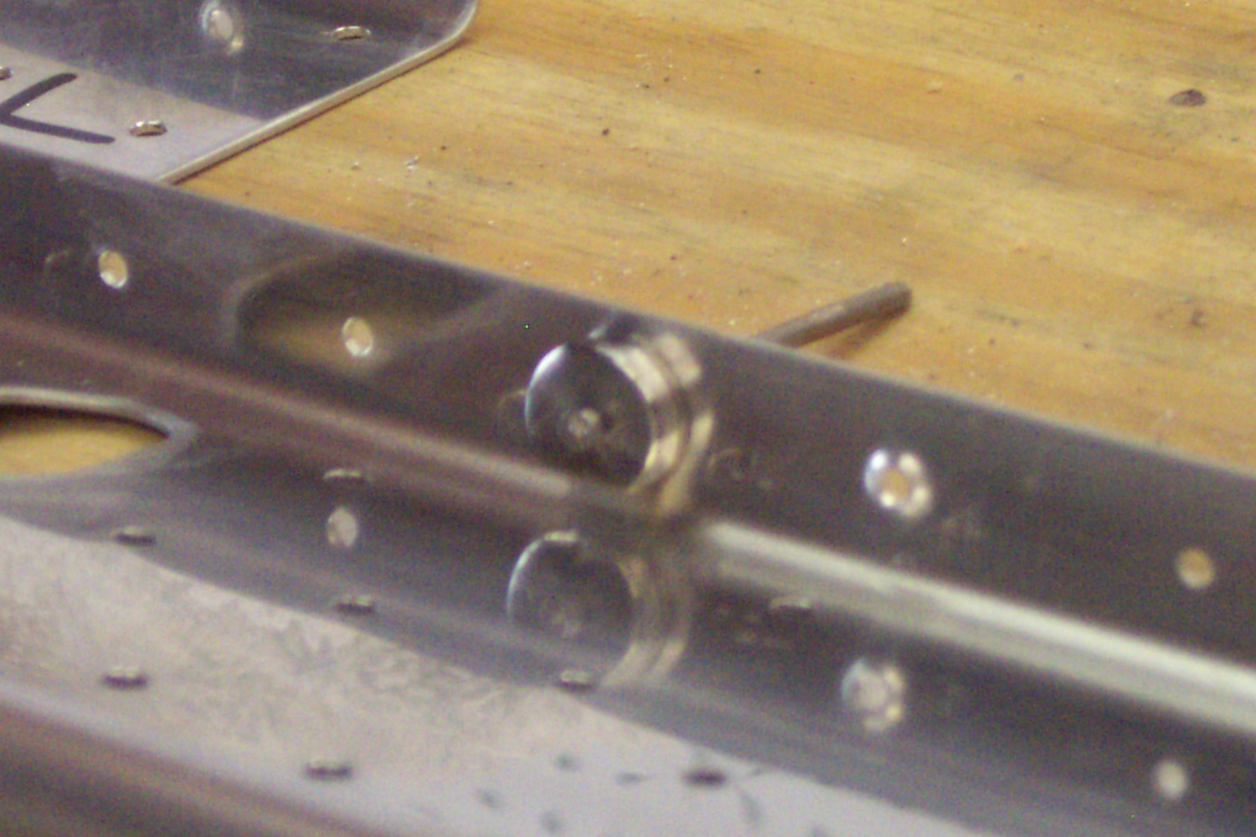
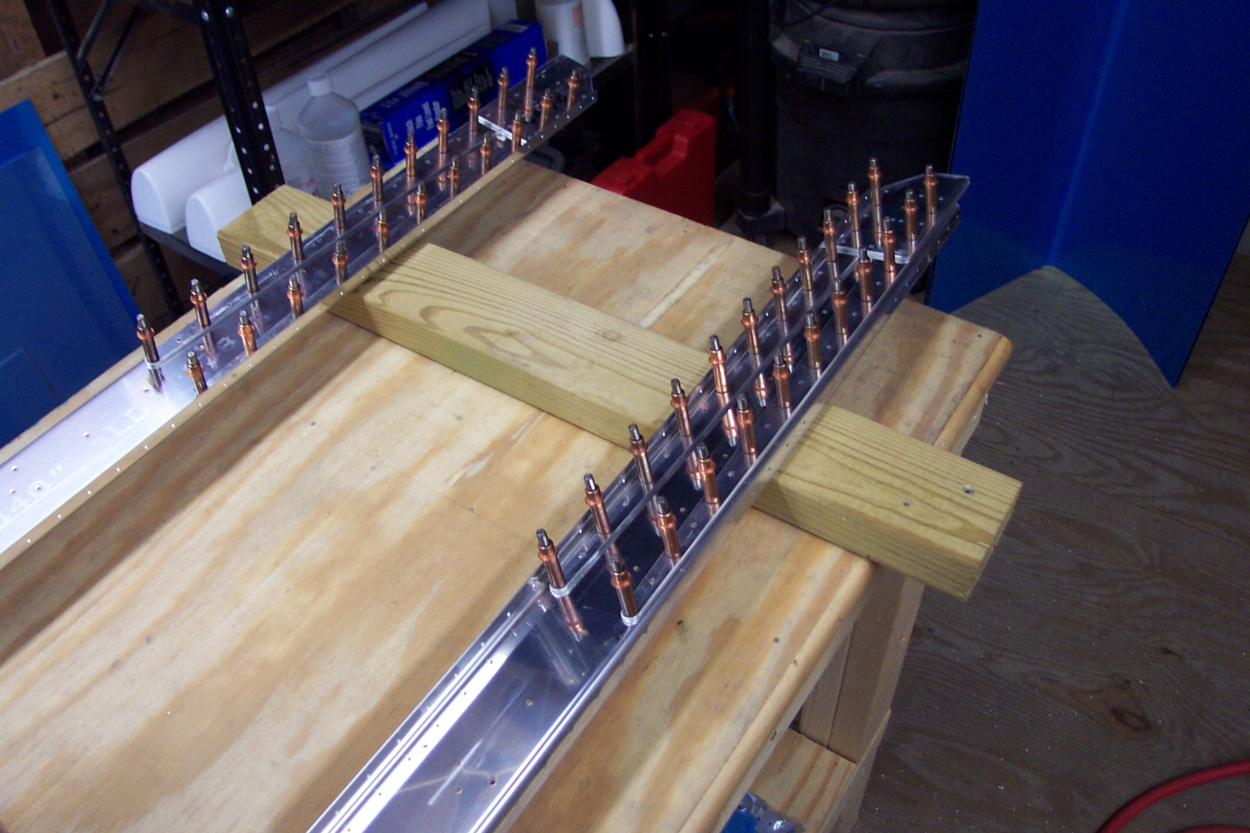
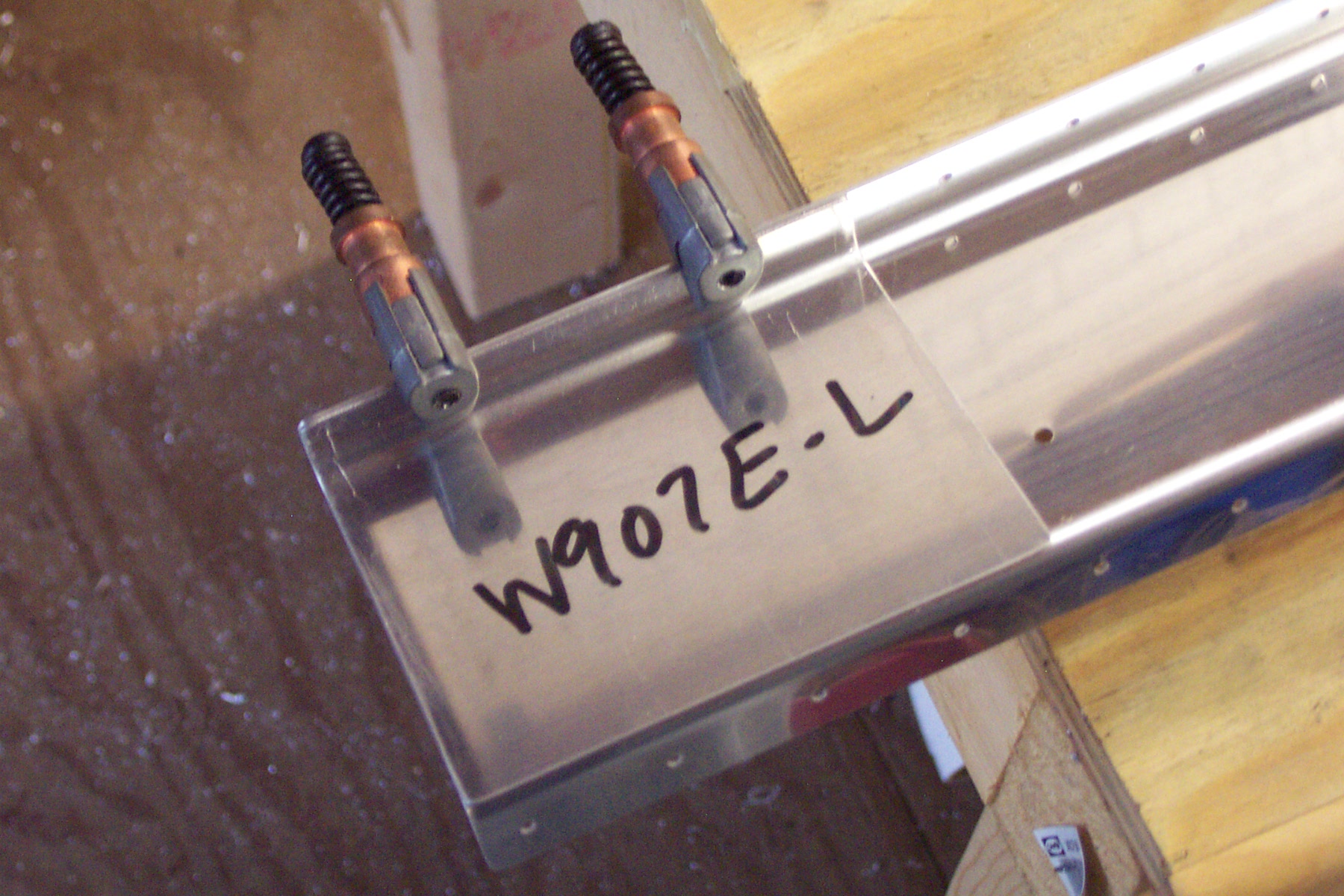
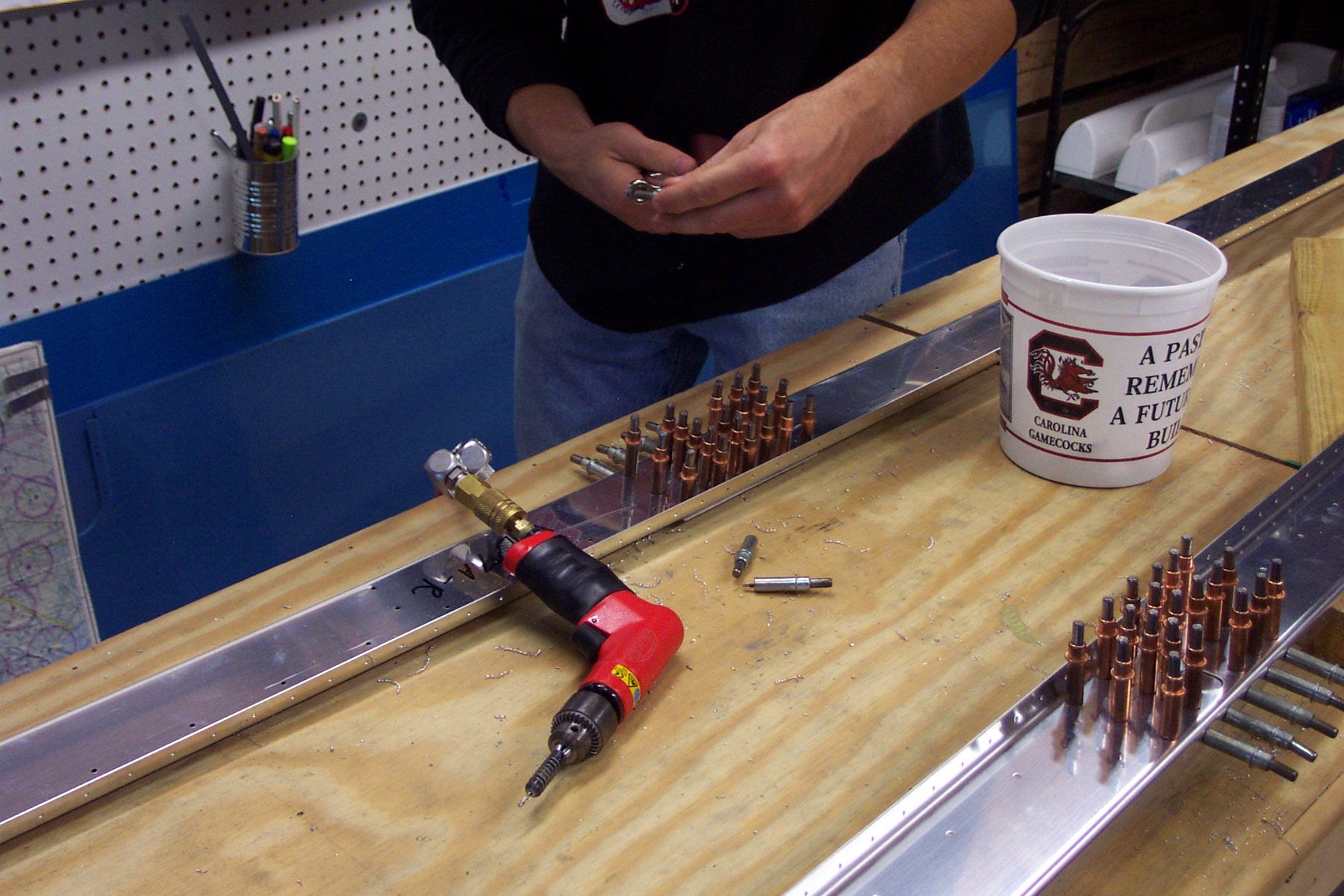
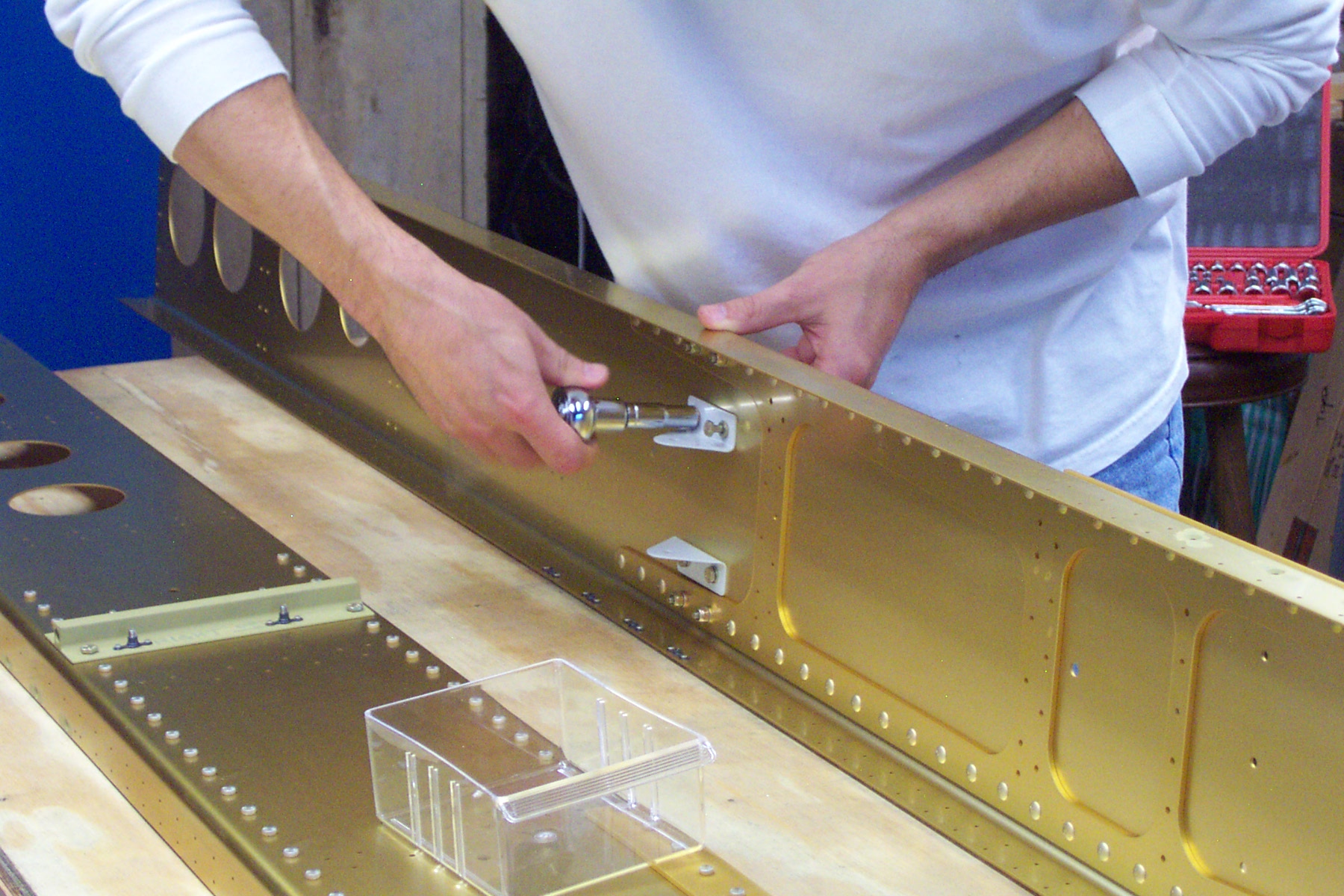
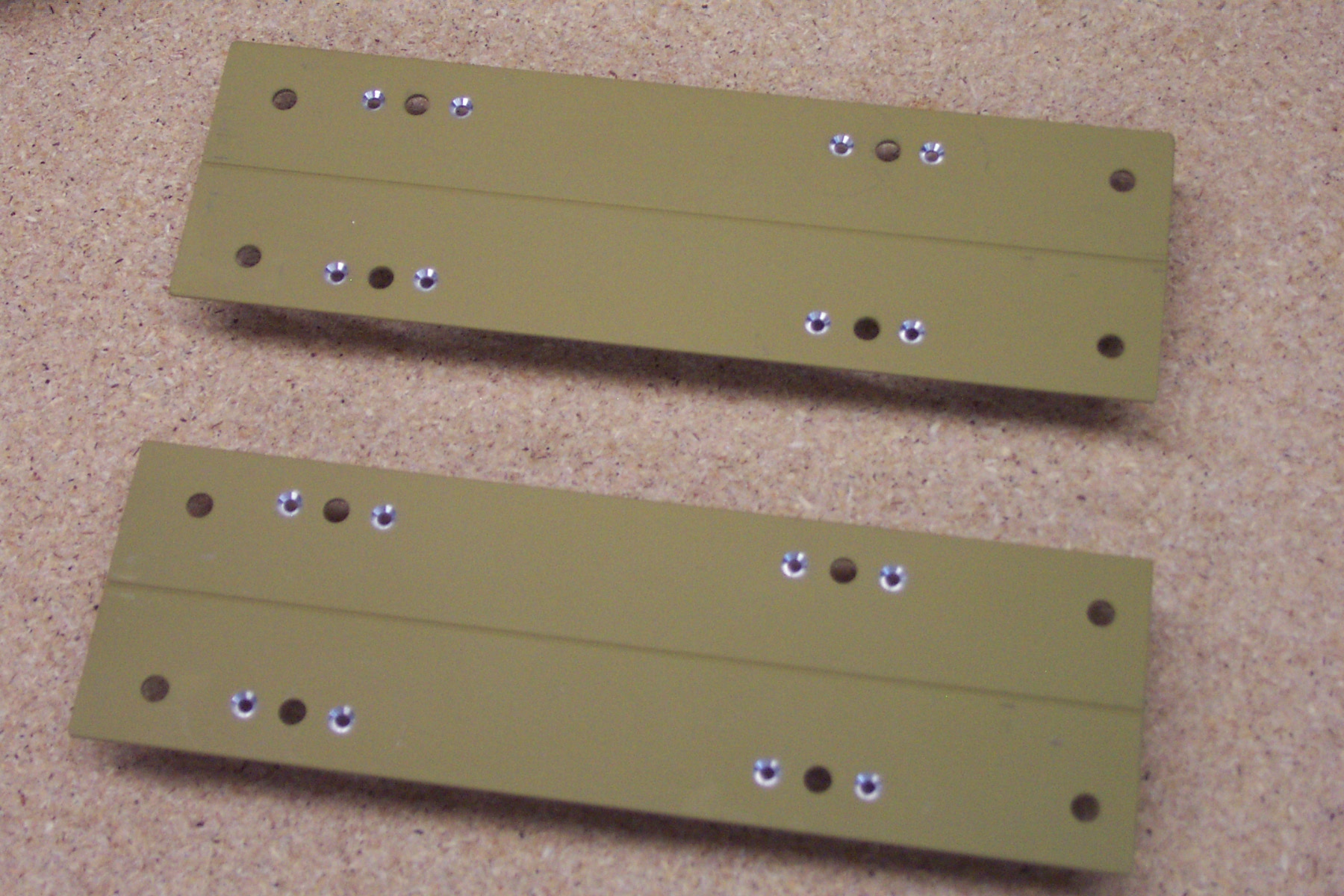
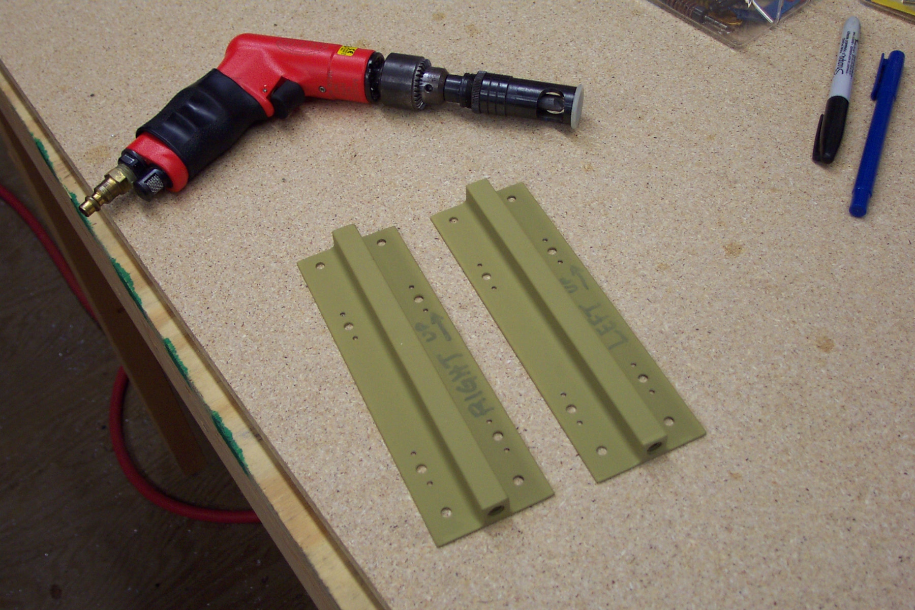
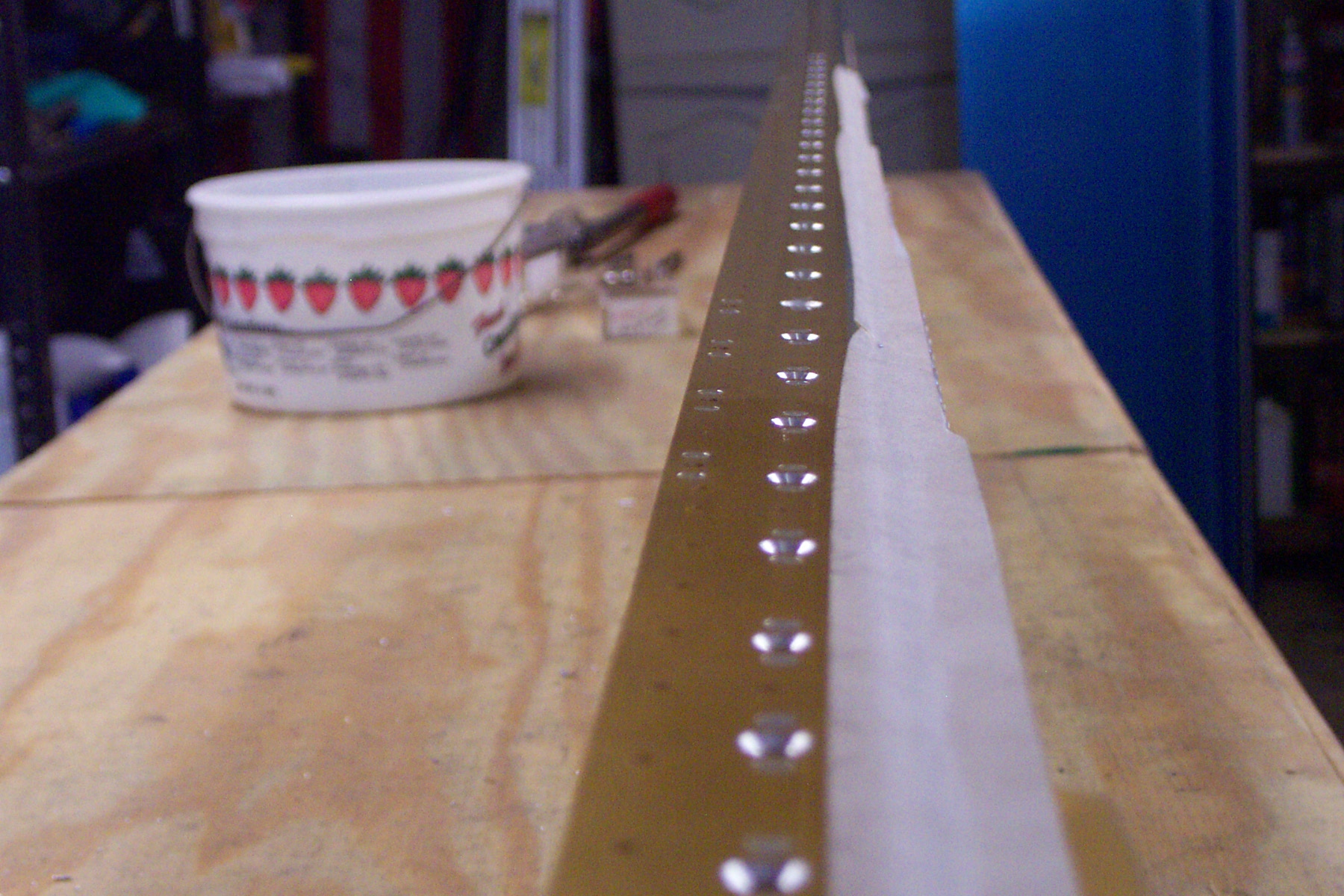
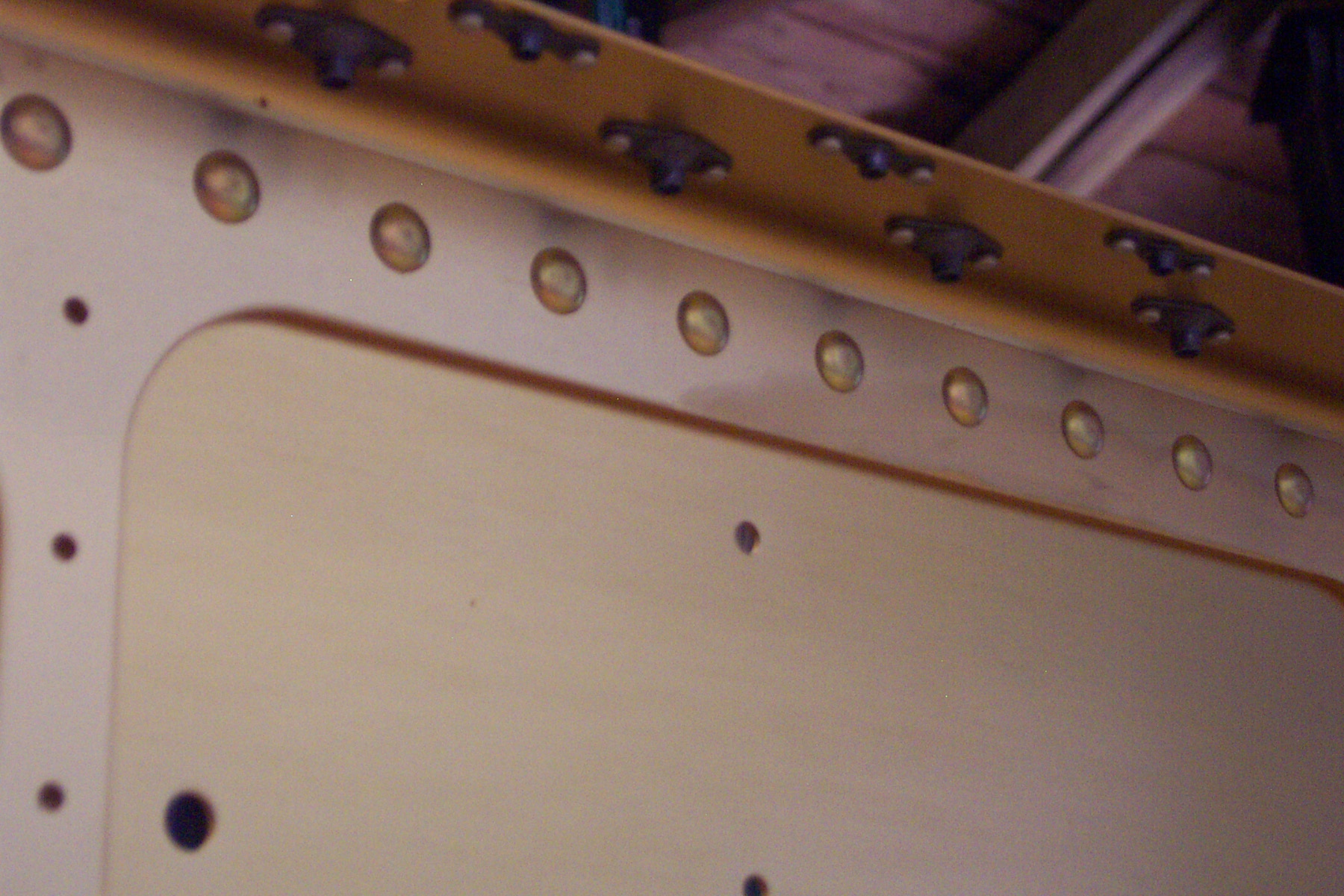
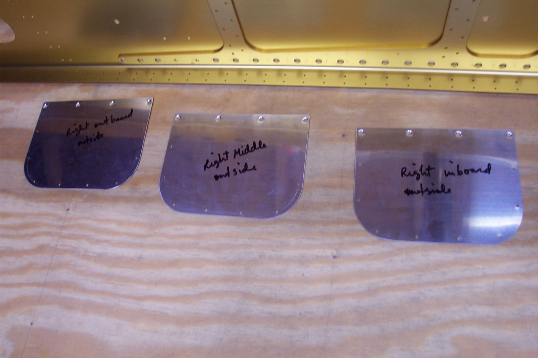
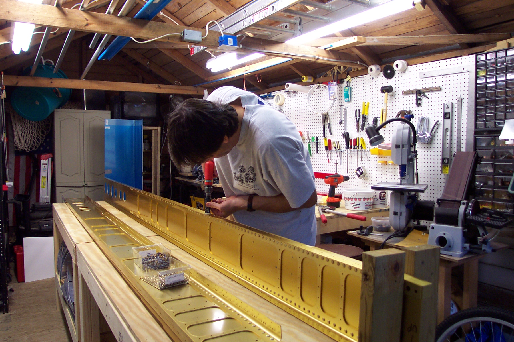
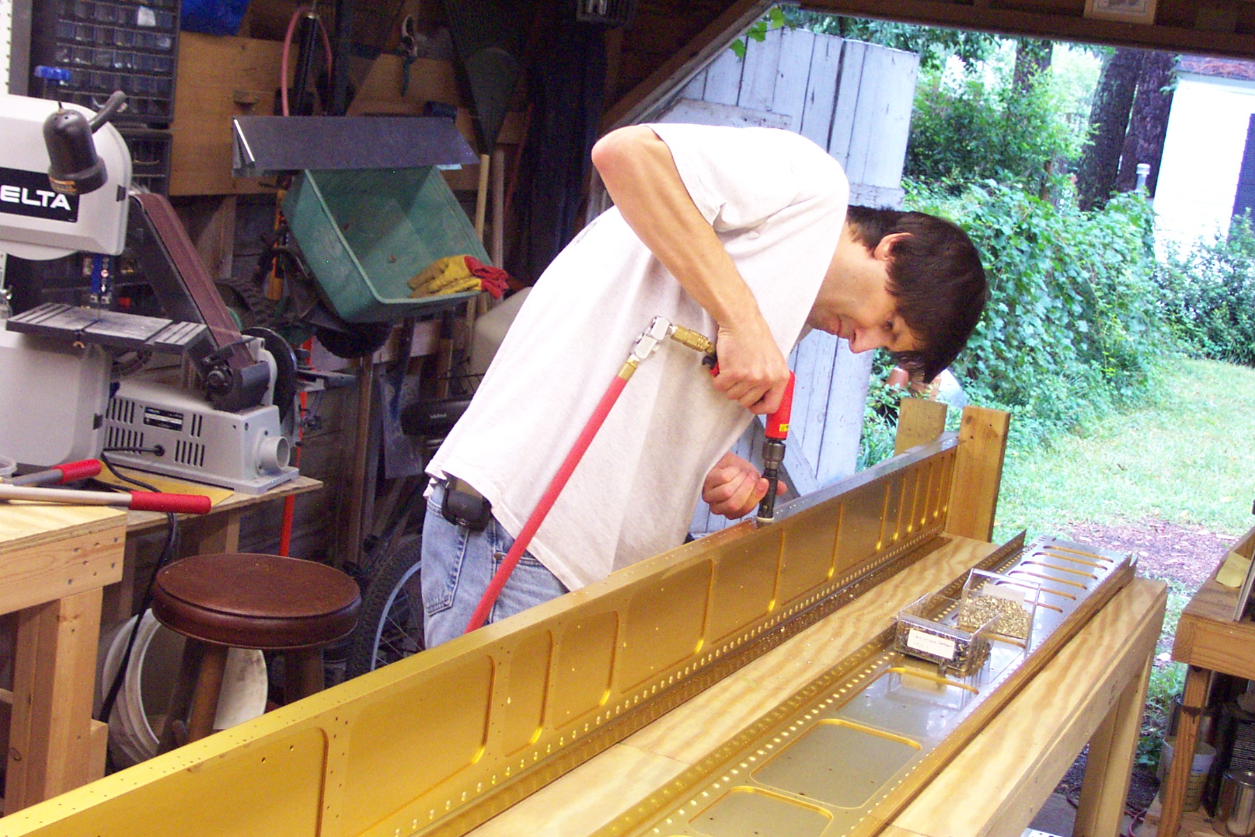
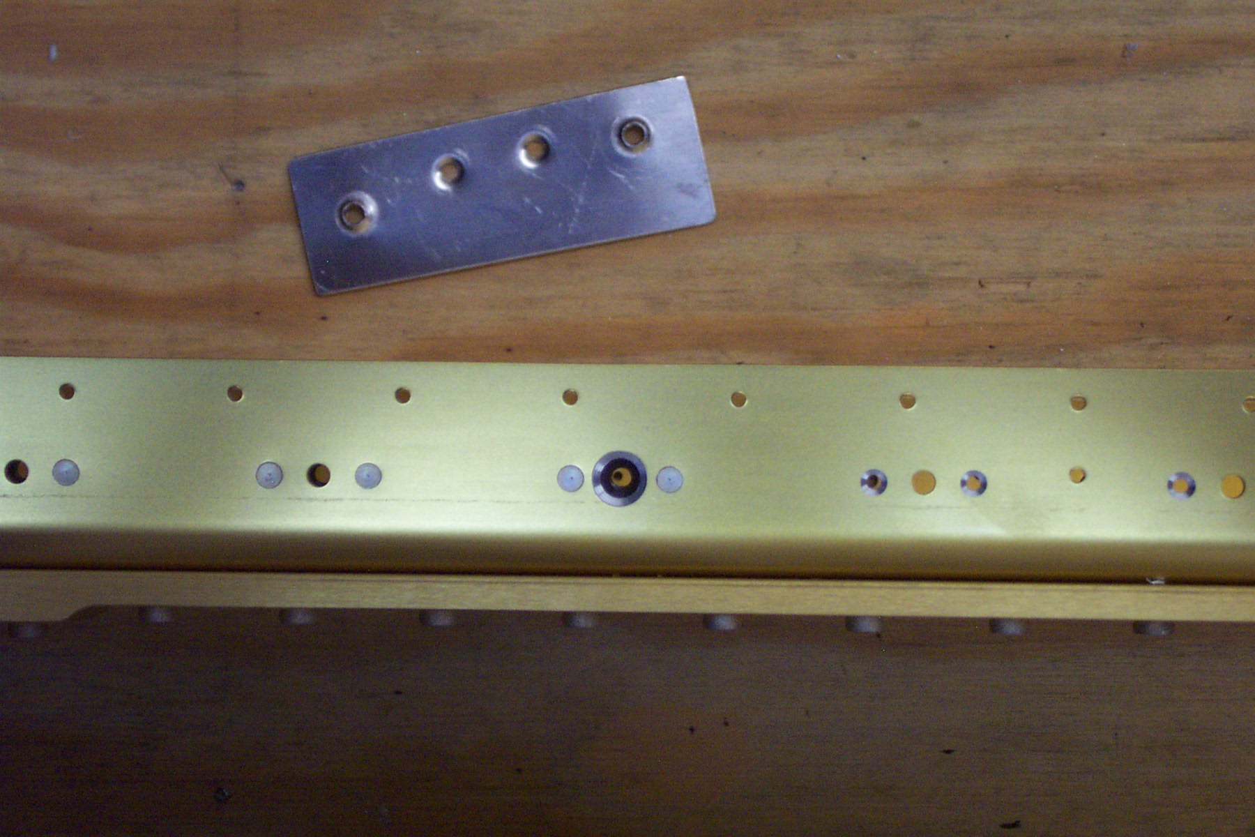
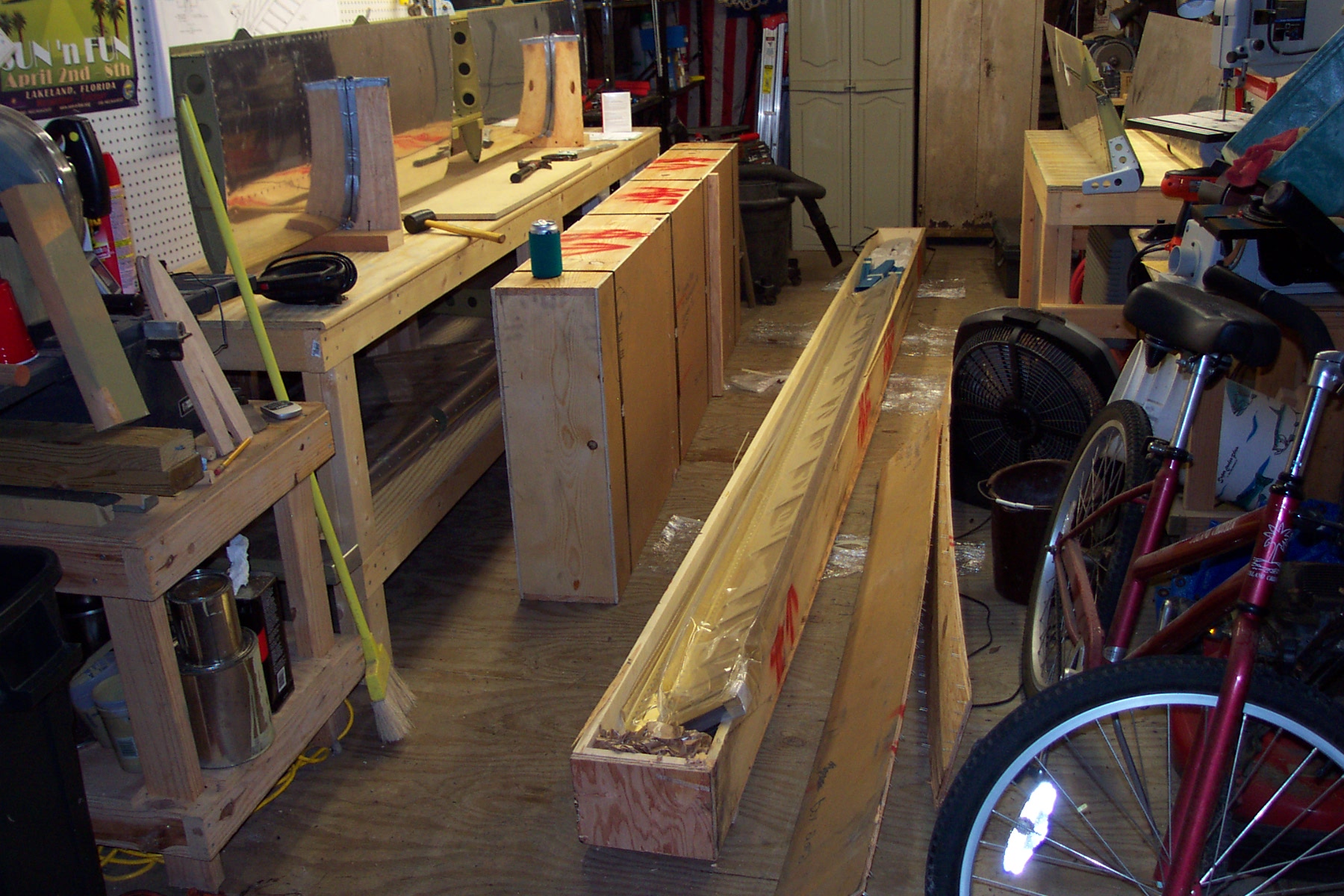
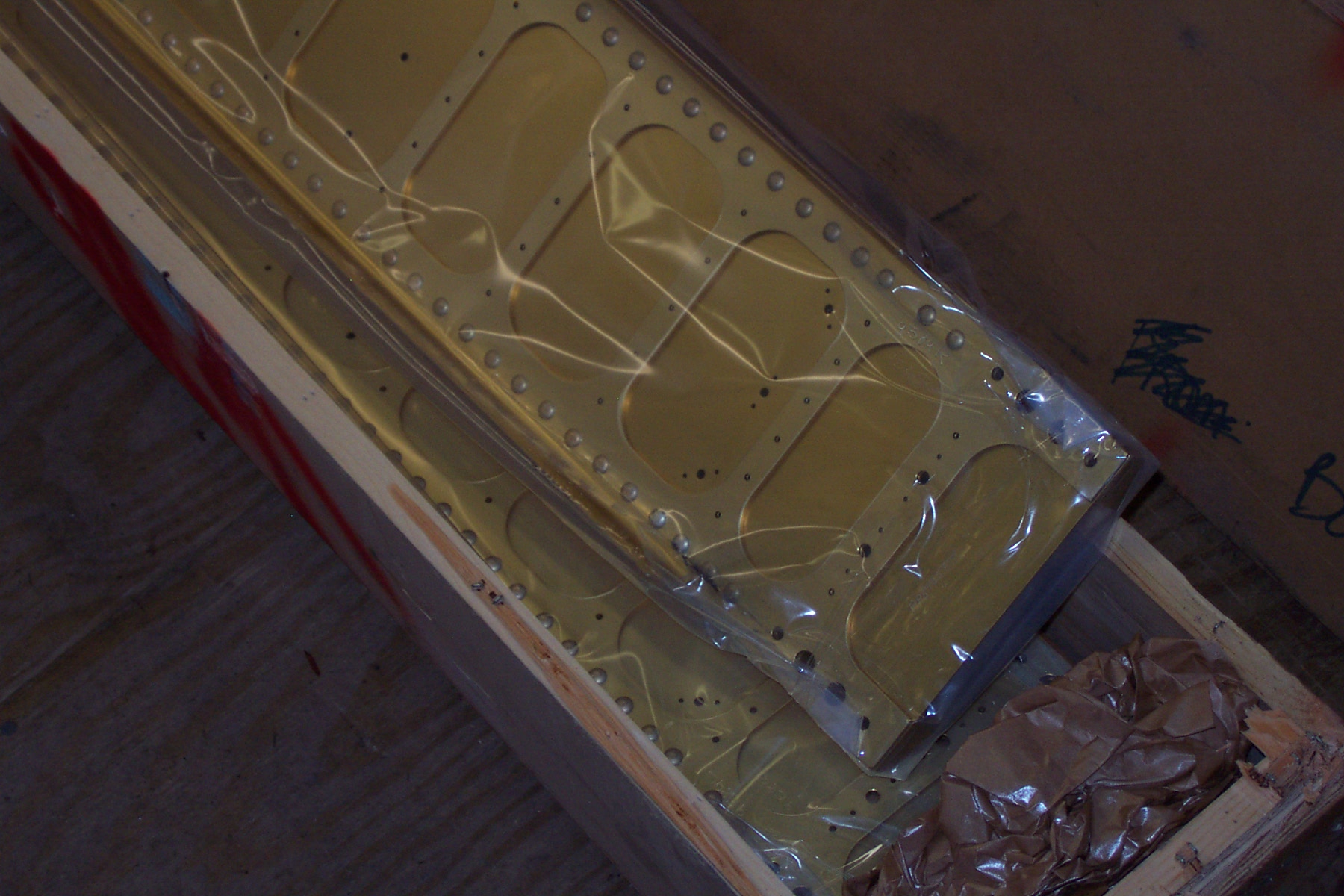