|
|
|
|
|
|
Official building time: 2224.3 hours.
|
|
|
Building time for Firewall Forward: 378.5 hours.
Number of records for Firewall Forward: 104. |
|
2014-04-14 |
Hours: 2 |
Category:
Firewall Forward
|
|
Manual Ref:
|
ID#:
1196
|
|
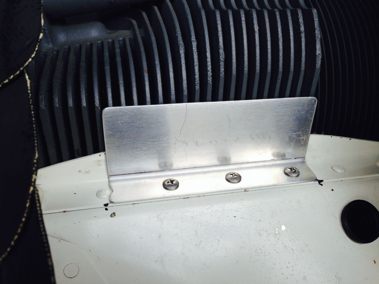
Added air dam to number one cylinder |
|
I had removed the previously riveted air dams from in front of numbers one and two cylinders as they were causing high temps. Number one is coolest by about 20 degrees so I recently added some foil tape and tested. The final amount added resulted in cylinder one matching two and three, with number four now coolest by about six degrees. I made an air dam out of some .040 and attached it to the baffling using three of the rivets holes that existed in the horizontal flange that supports the ramp. I will have to fly again to see if this air dam has the same effect as the foil of the same profile.
|
|
|
2011-09-10 |
Hours: 4 |
Category:
Firewall Forward
|
|
Manual Ref:
|
ID#:
1168
|
|
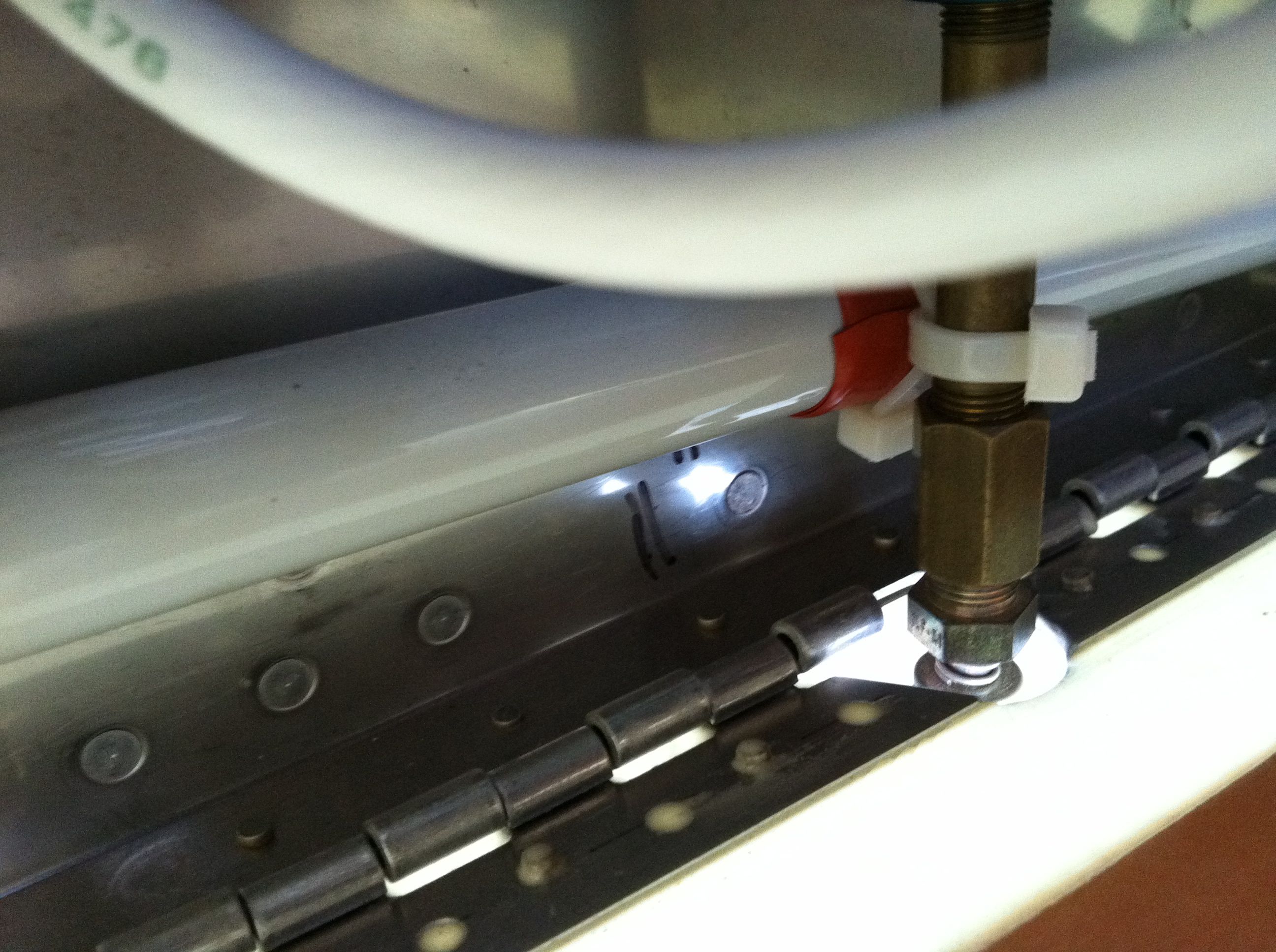
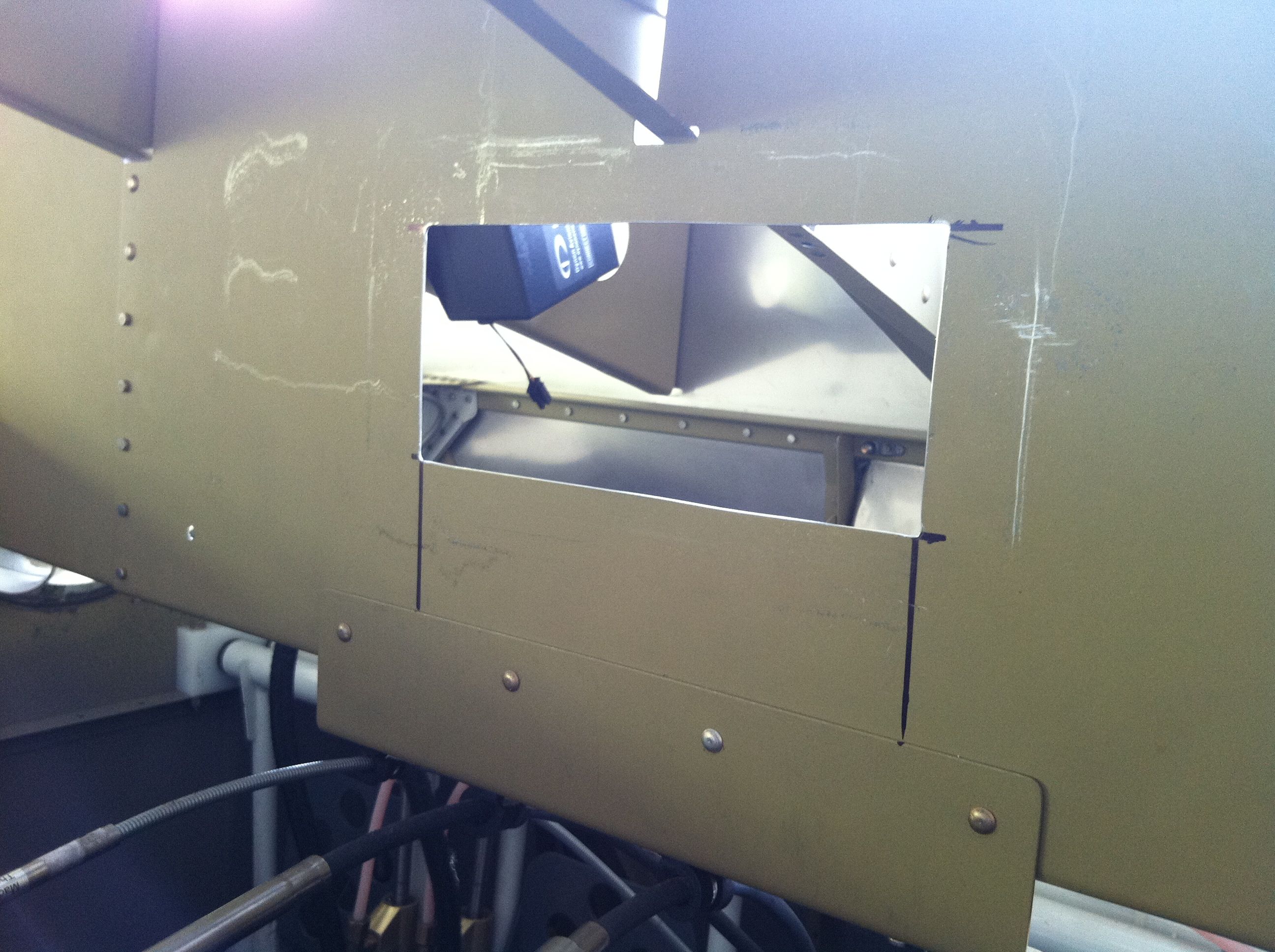
Finally got around to cutting a slot out of the bottom of the bottom cowl to clear the fuel drain installed in the gascolator. Also started assembling the various antenna cables. Borrowed a great little tool from Ken that makes all the cuts on the cable to install the BNC connector. What a great tool! Not sure where this particular tool was purchased but you can find cable strippers at Radioshack.
|
|
|
2011-08-14 |
Hours: 4 |
Category:
Firewall Forward
|
|
Manual Ref:
|
ID#:
1167
|
|
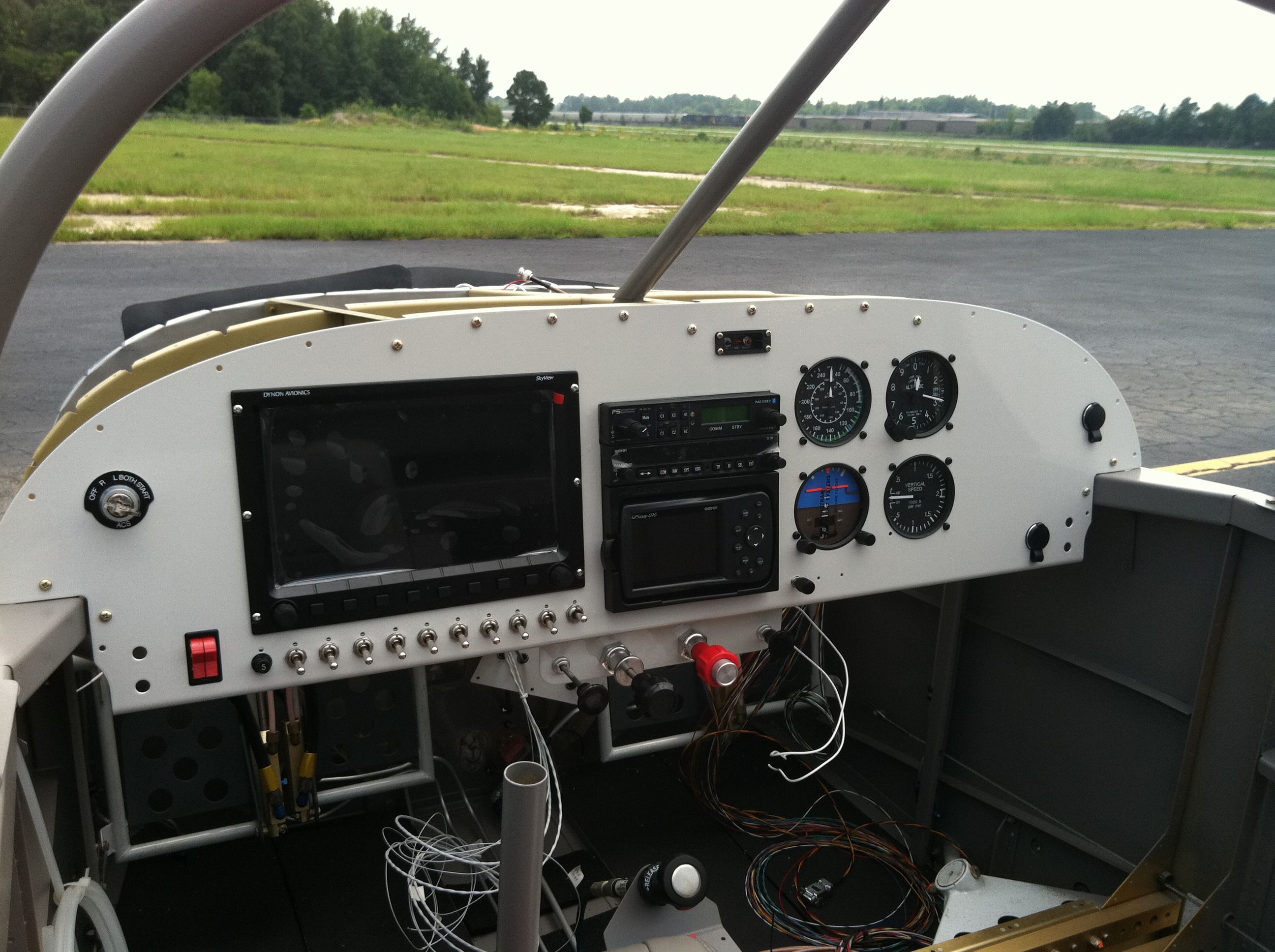
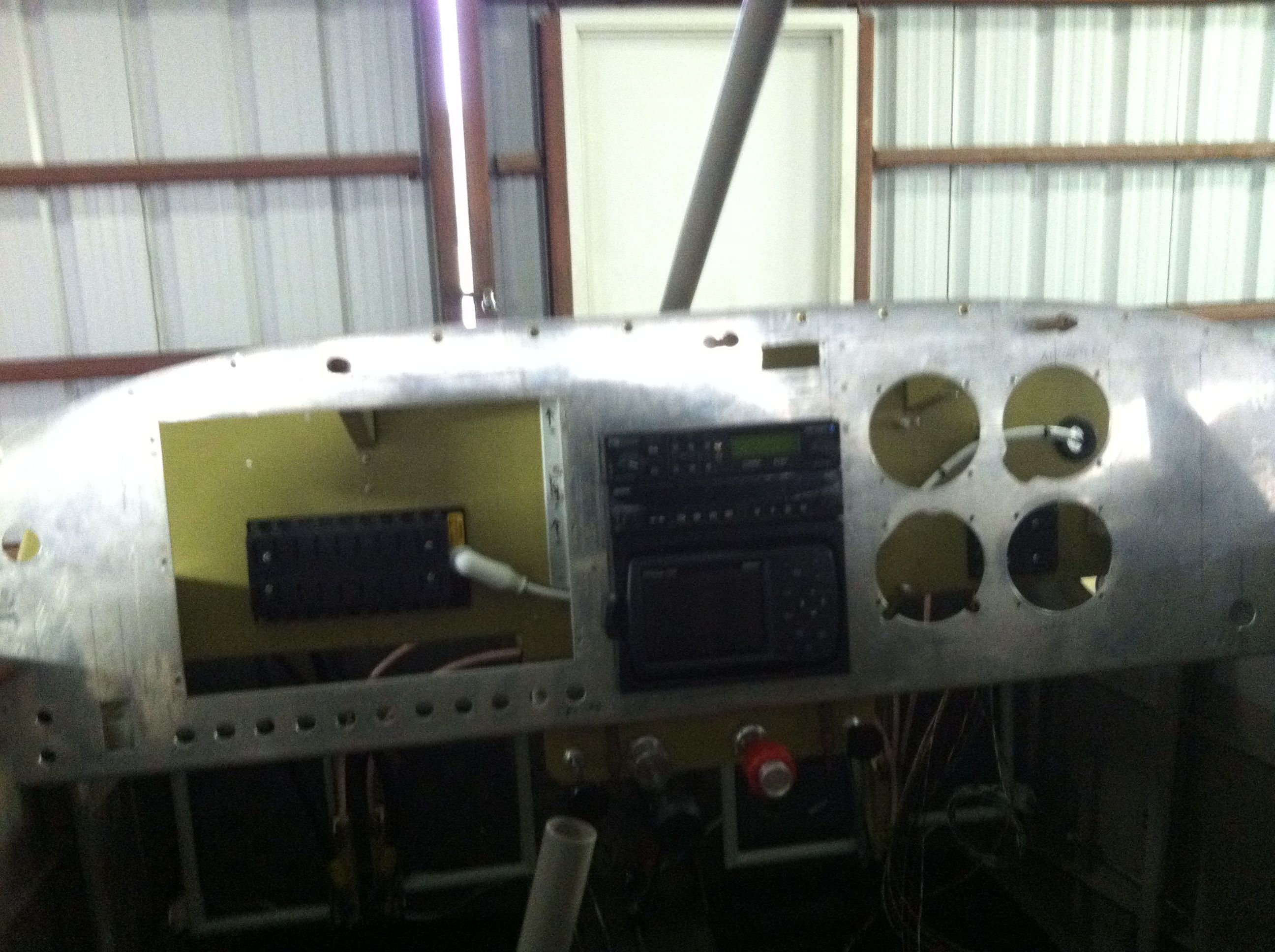
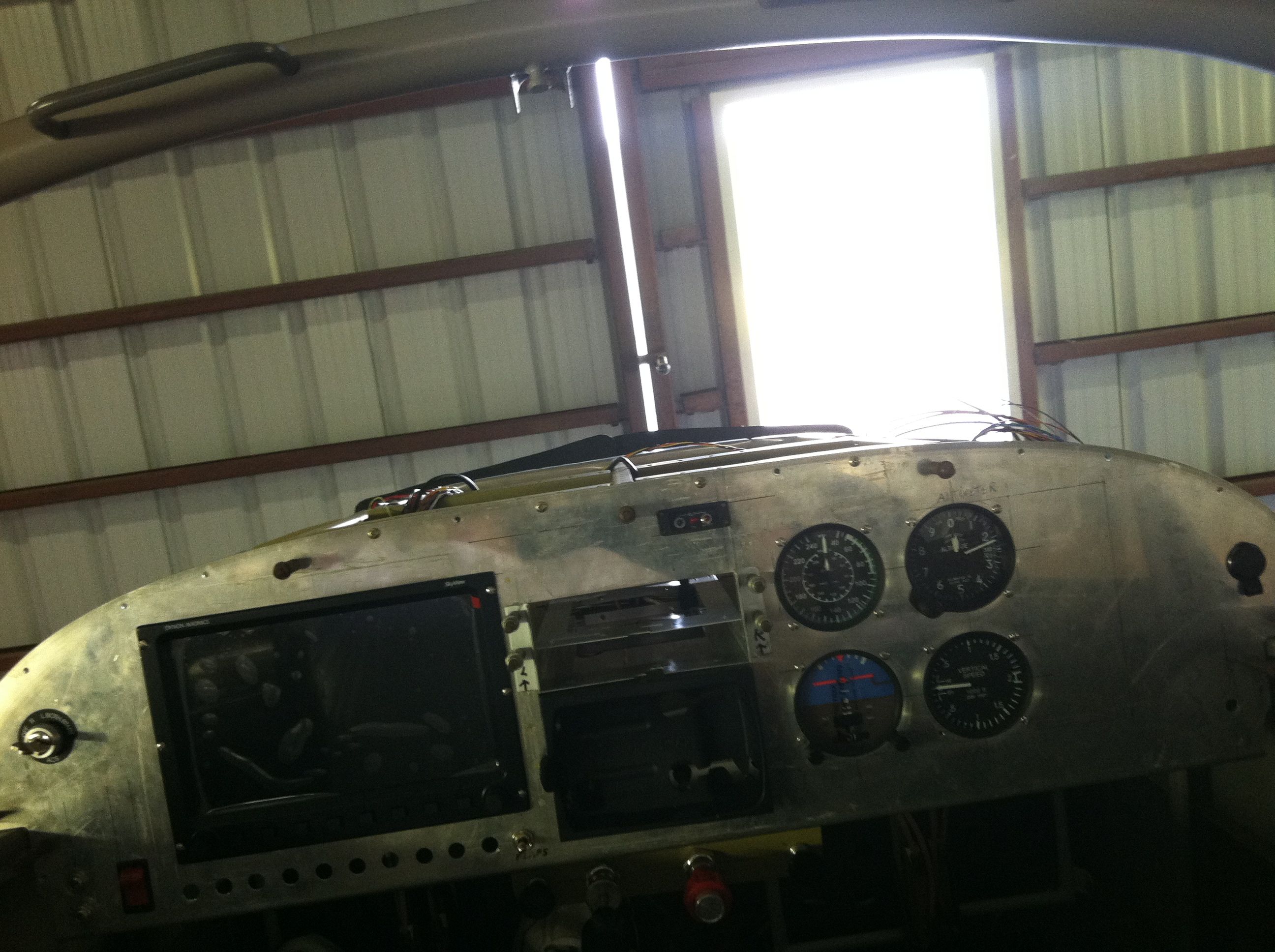
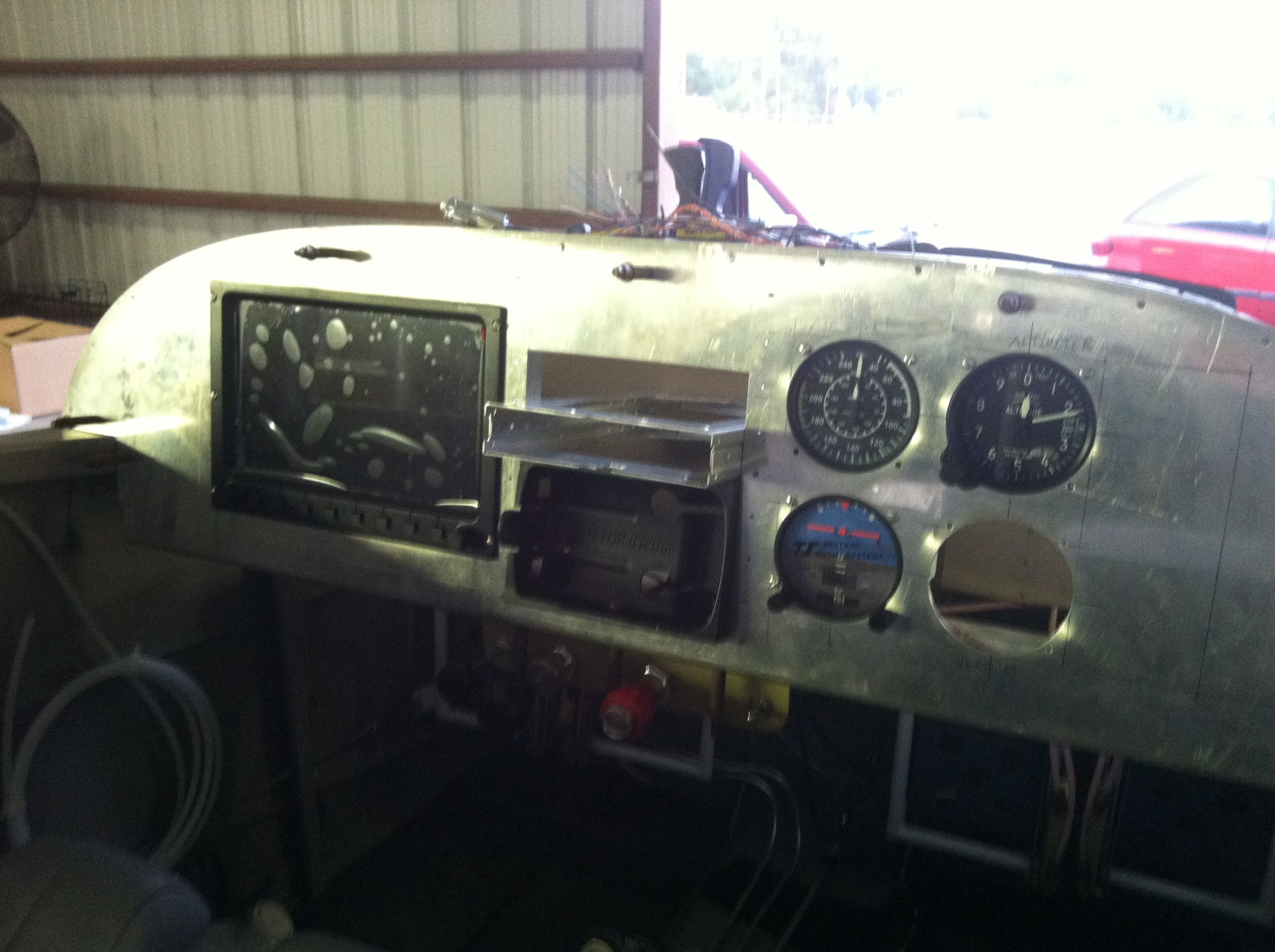
Panel painted, installed some avionics |
|
Painted my panel two days ago with Jetglo Stone Grey. I am really impressed with the paint itself. My work with it turned out okay. There are a few fisheye bubbles and lots of tiny ones, but they are not very noticable. I am pleased with the end result. I installed most everything back in the panel hopefully for the last time. Now to get it all wired.
|
|
|
2011-08-07 |
Hours: 3 |
Category:
Firewall Forward
|
|
Manual Ref:
|
ID#:
1166
|
|
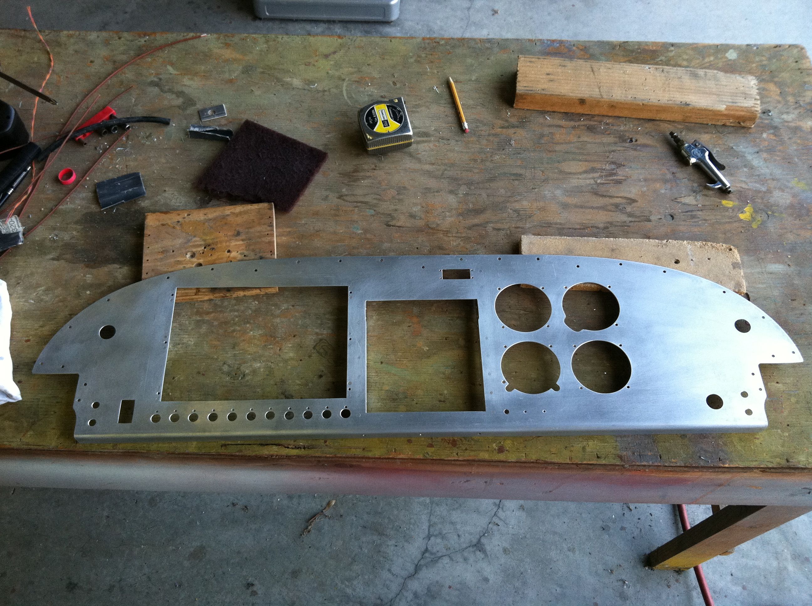
Removed panel to prep it for painting |
|
I removed all the panel items and took the panel out of the fuse to prepare it for priming and painting. Still not sure what color I will use.
|
|
|
2011-08-06 |
Hours: 5 |
Category:
Firewall Forward
|
|
Manual Ref:
|
ID#:
1165
|
|
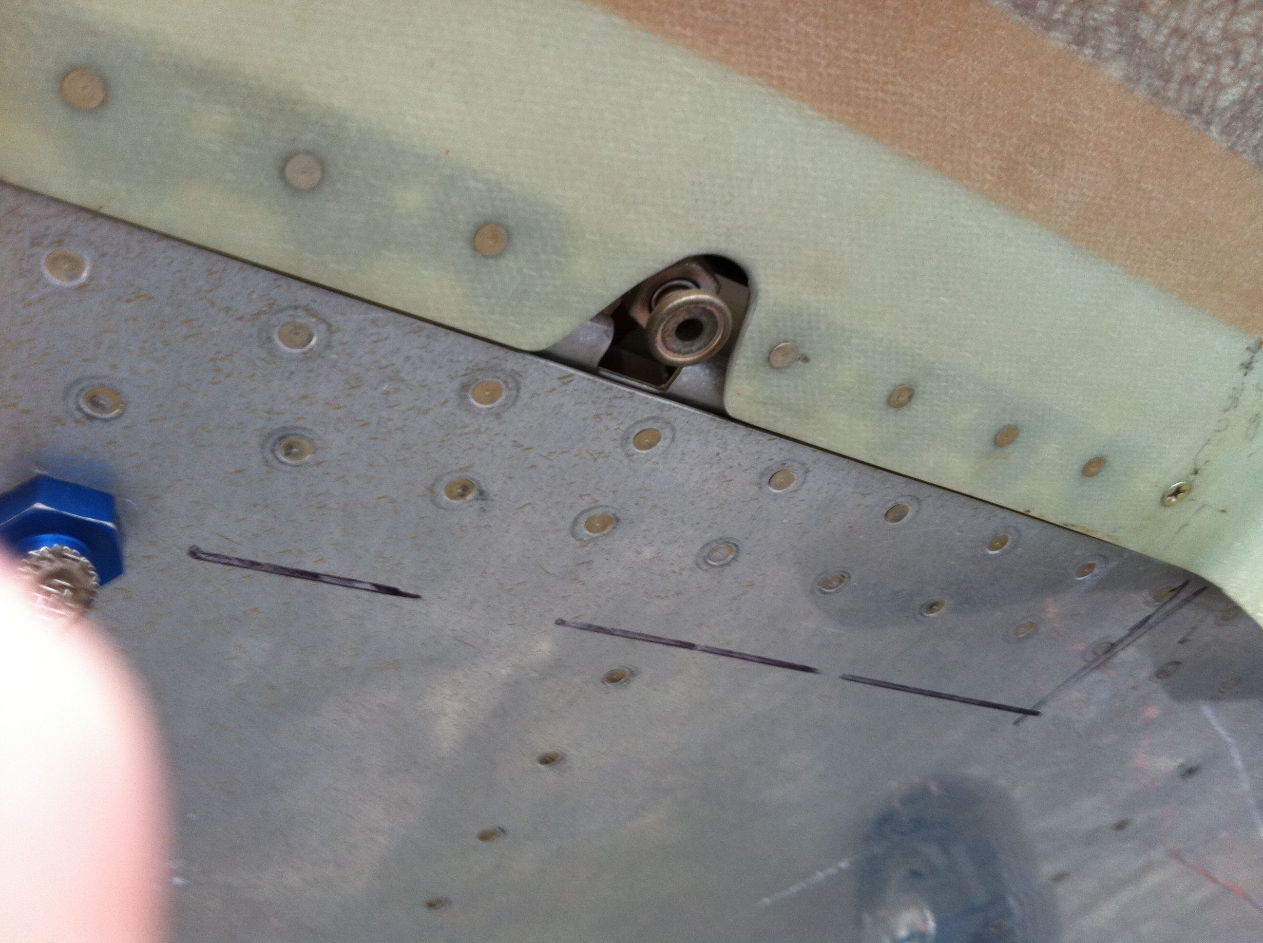
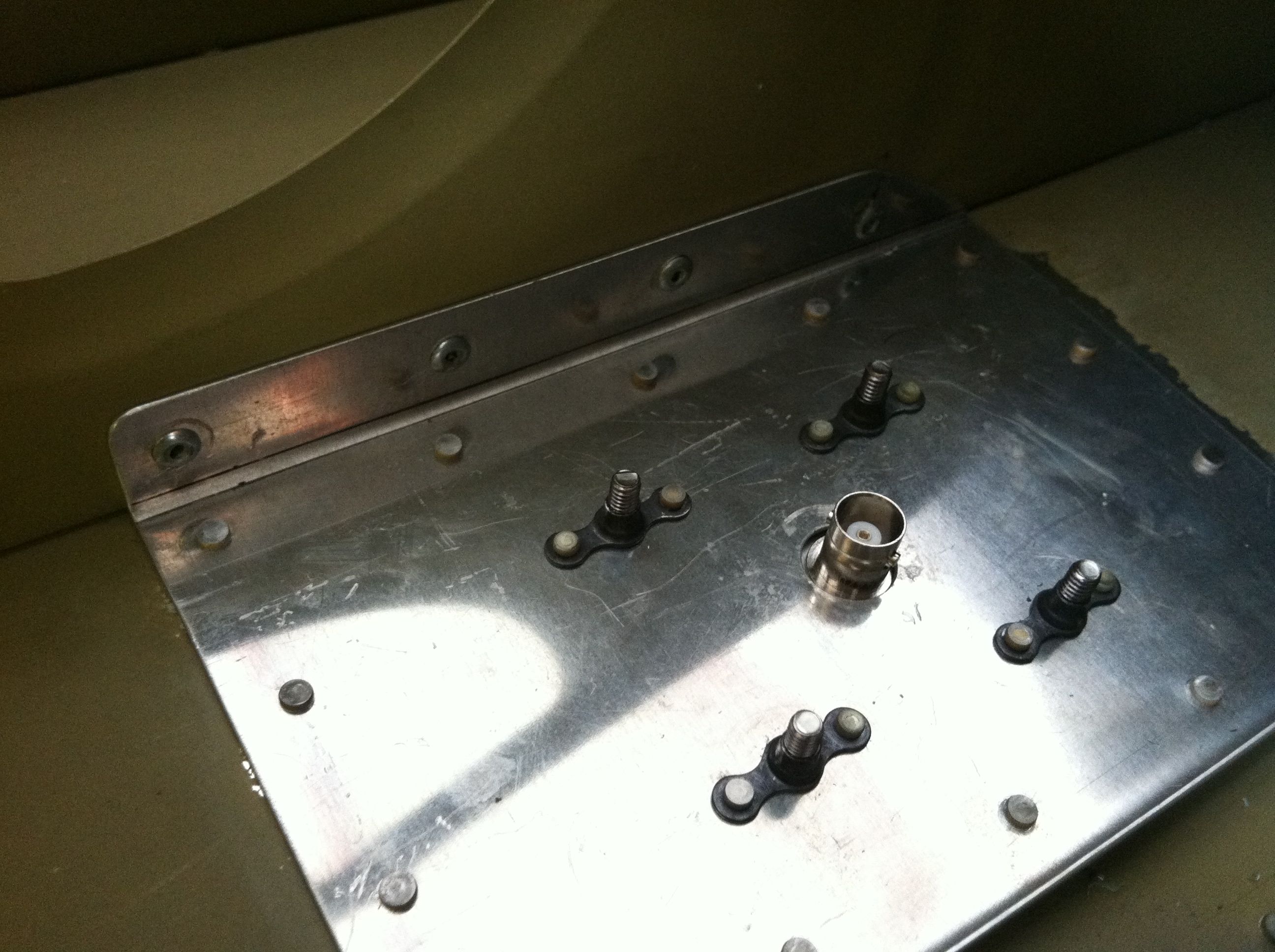
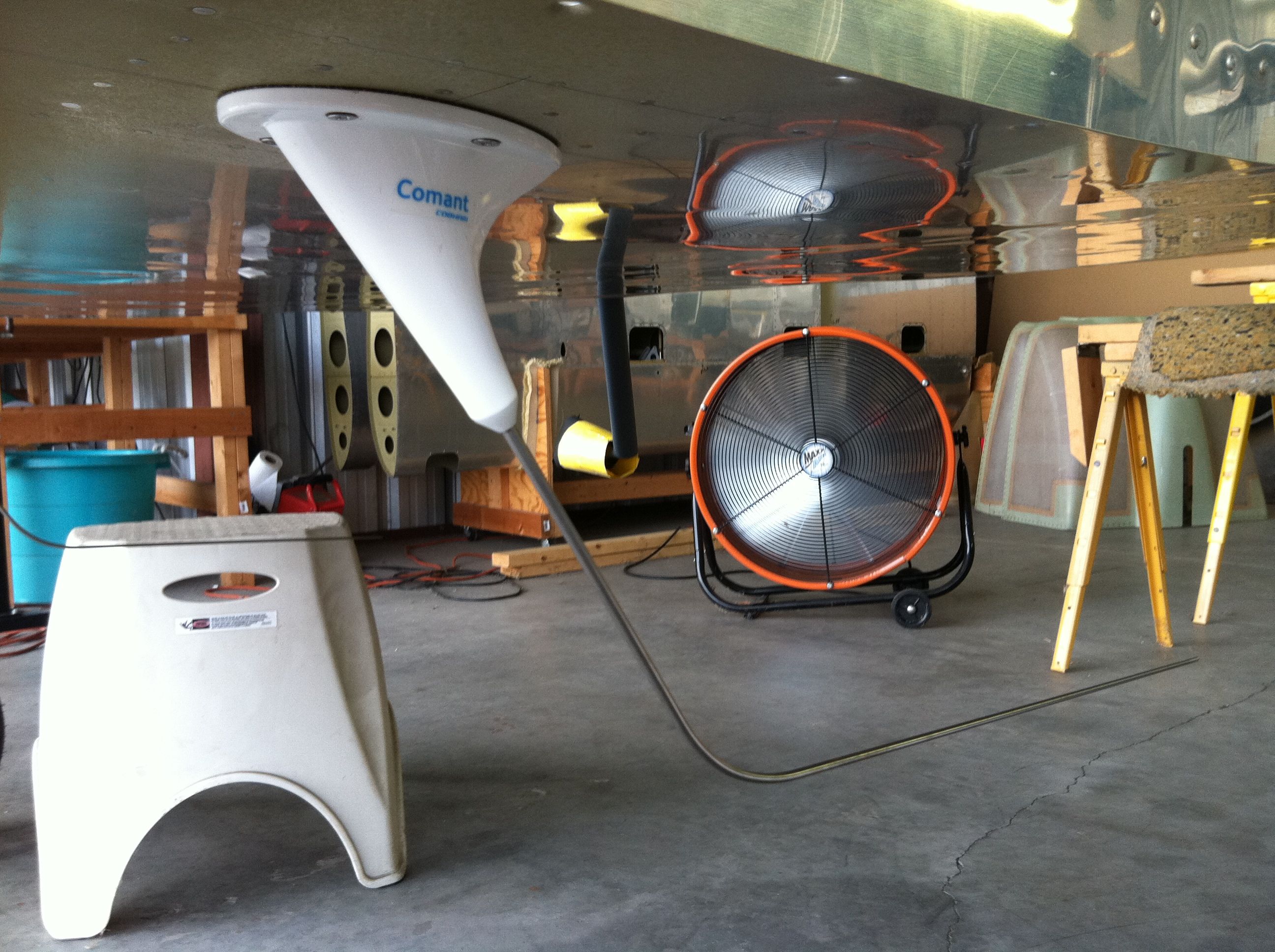
Installed two Comant 122 comm antennas on the bottom of the center fuse on the left and right outboard bays about an inch aft of the aileron push tube holes. I removed the primer from the inside of the bottom skin, and riveted the antenna reinforcement plate to the bottom skin and the next to outboard seat rib.
|
|
|
2011-07-14 |
Hours: 3.5 |
Category:
Firewall Forward
|
|
Manual Ref:
|
ID#:
1164
|
|
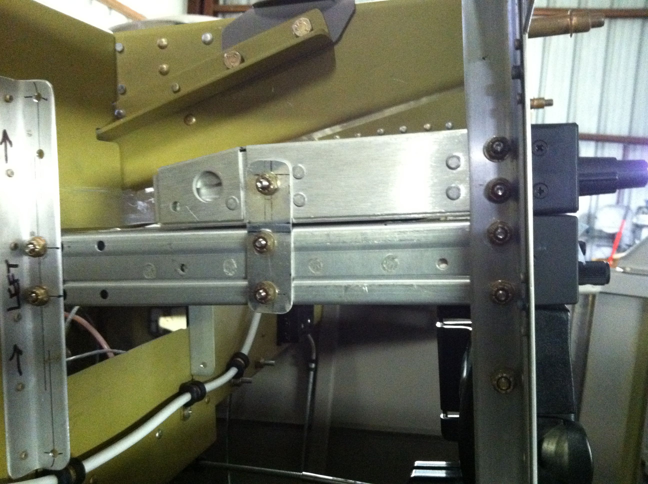
Finished installing the radio stack mounts |
|
Test fitted my radio stack after finishing installing the mounts. I attached the SL-30 and PS Engr PAR100EX trays together with pieces of 0.040. Had to put a joggle in them because the tray for the PAR100EX is slightly wider at 6.31 inches versus the SL-30 tray at 6.25". Also anchored the SL-30 tray on vertical angles riveted to the subpanel. The whole structure is very sturdy and solid.
|
|
|
2011-07-13 |
Hours: 4.5 |
Category:
Firewall Forward
|
|
Manual Ref:
|
ID#:
1163
|
|
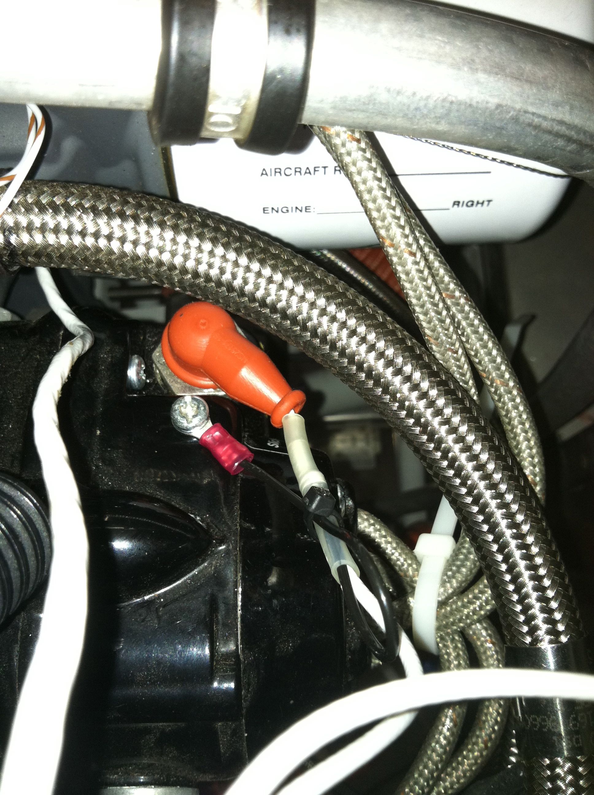
Made up my left and right p=leads from shields 18 ga. I used black 18 ga. wire soldered and shrink tubed to the shield for the ground lead at the mags via the method I found on Aeroelectrics website. I installed the mag wires and ran them to the inlet in the firewall. The nut on the mag does not require much to tighten. Be careful not to over tighten. I believe it calls for 12-13 in#.
|
|
|
2011-07-07 |
Hours: 4 |
Category:
Firewall Forward
|
|
Manual Ref:
|
ID#:
1162
|
|
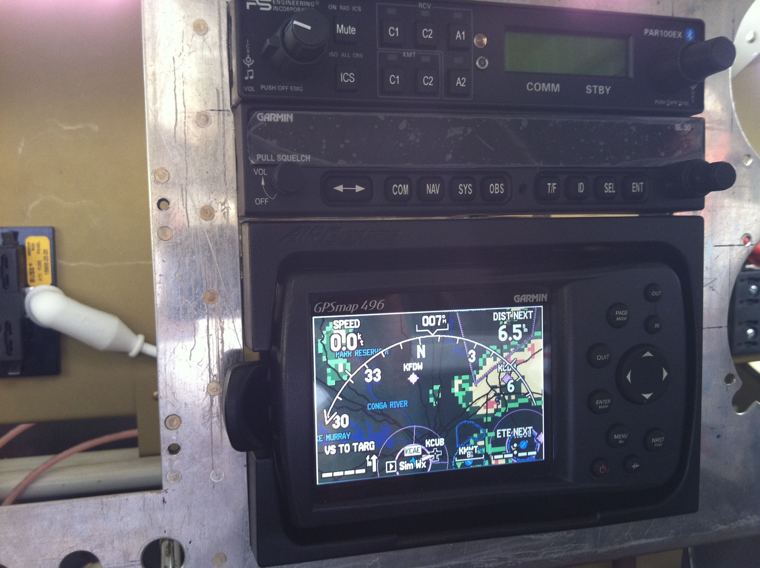
Installing radio mount trays in the panel |
|
Received my PS Engineering PAR100EX today! Nice looking unit. I got busy installing the mount trays for the PAR100EX and the Garmin SL-30. I had previously riveted aluminum angle in the radio stack to attached the mount trays to. The PAR100EX is actually 6.31", not 6.25" as is the SL-30 tray, so I spent a lot of time and elbow grease filing away aluminum until the width of the opening would accept the PAR100EX tray. Positioned carefully and drilled the screw holes and installed the trays to see how they fit.
|
|
|
2011-07-02 |
Hours: 4 |
Category:
Firewall Forward
|
|
Manual Ref:
|
ID#:
1161
|
|
Cut the holes in the control panel for the master/alt switch, ELT remote and the headset jacks. Also riveted the two pieces of angle at the radio stack to the panel. I riveted them double flush so that instrument mount tray bolts will not interfere with the rivet shop heads.
|
|
|
2011-07-01 |
Hours: 4.5 |
Category:
Firewall Forward
|
|
Manual Ref:
|
ID#:
1160
|
|
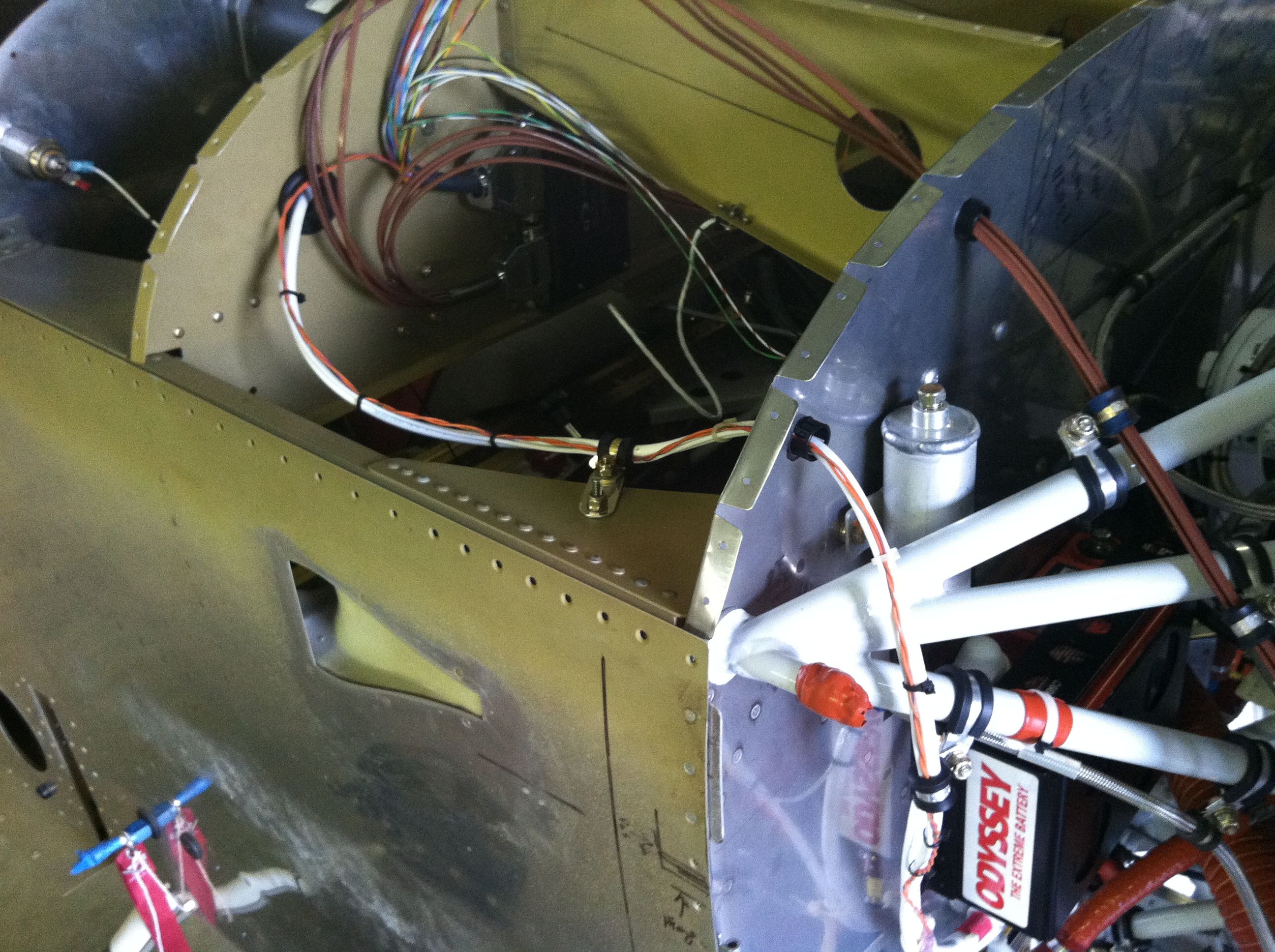
Installed main buss power cable |
|
After contemplating where to enter the firewall with the main and battery buss power wires, I decided to use the hole I had cut in the firewall for the probe wires on the right side above the engine mount bolt, and drill a new hole above the brake fluid reservoir to run the probe wiring. I ran the cables through an adel clamp attached to the gusset and into a 1.25" hole in the sub panel with a large grommet, over to the main buss fuse block via a few adel clamps.
|
|
|
2011-06-18 |
Hours: 3.5 |
Category:
Firewall Forward
|
|
Manual Ref:
|
ID#:
1159
|
|
Drilled the switch holes in the panel. Routed some of the Dynon EMS wires through the subpanel out to the FWF. Just kinda running wires to see how they all might end up. Cut some strips of 5/8" wide .063 alclad 2.5" long to use as stand offs for the EGT and CHT sensor wires to keep them away from the spark plug wires at each cylinder.
|
|
|
2011-06-09 |
Hours: 4 |
Category:
Firewall Forward
|
|
Manual Ref:
|
ID#:
1158
|
|
Cut a hole in the sub panel for the radio tray |
|
I marked and cut the hole for the SL-30 radio tray through the sub panel. I cut it deeper than the SL-30 requires in case I decide to add, say, a Garmin GTN 650 or something some day. :)) After test fitting the tray, I had to take more material off the top of the hole to get the tray to sit flush with the panel. I clecoed two pieces of aluminum angle to the front of the panel, overlapping the radio hole enough so that the radio tray could be pushed up against the angles, thereby "guaranteeing" that the tray is flush with the face of the panel and perpendicular to it.
|
|
|
2011-06-08 |
Hours: 3.5 |
Category:
Firewall Forward
|
|
Manual Ref:
|
ID#:
1157
|
|
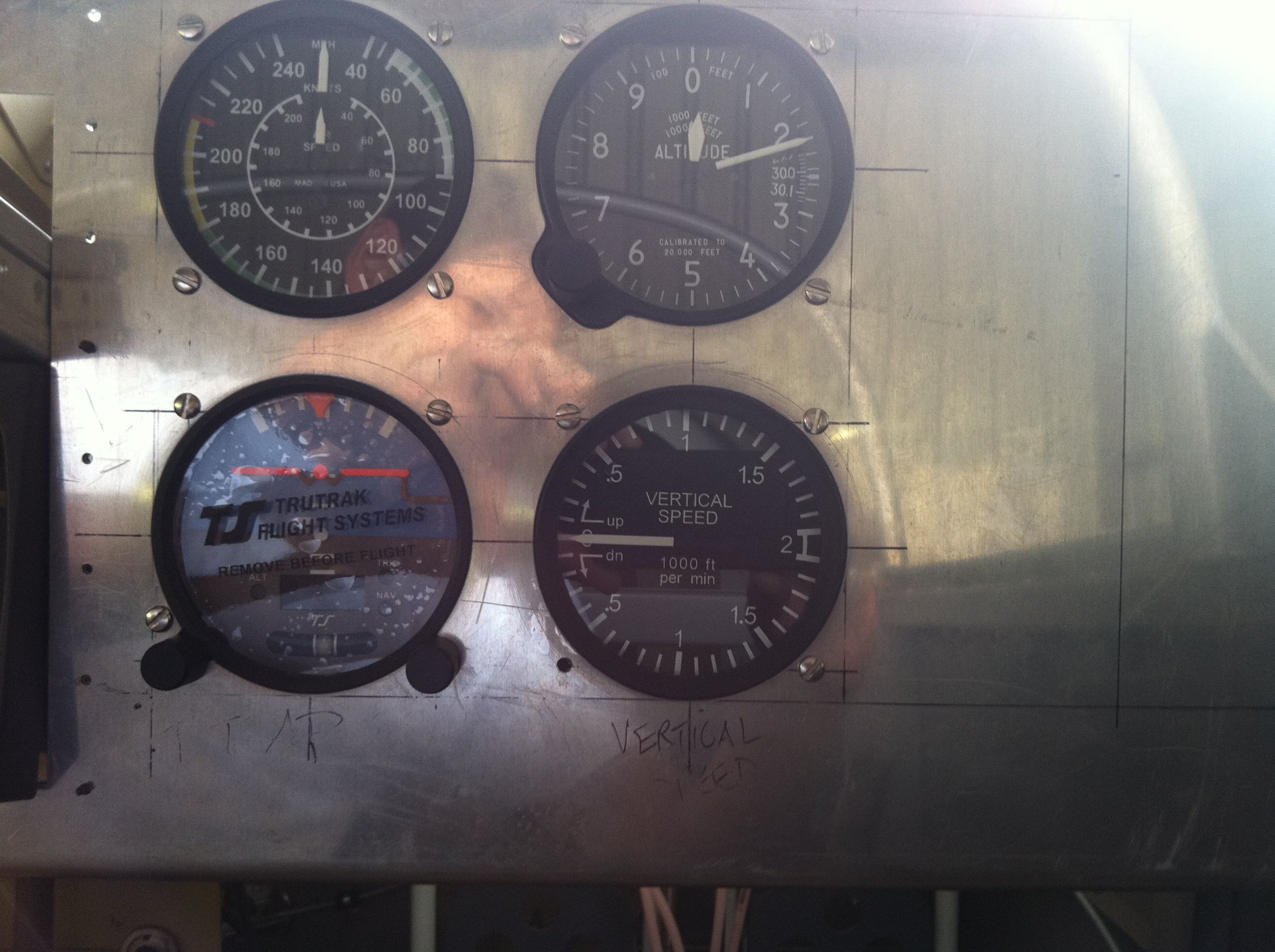
Finished modifying the right sub panel rib |
|
I finished modifying the right sub panel rib to allow clearance for the altimeter to fit in the panel. I used a seven inch length of 3/4" x 34" aluminum angle riveted to the rib web after cutting enough of the rib lower flange and web to allow the altimeter to fit. Also, my VSI and EZ Nuts instrument mount arrived from ACS so I installed them on each instrument. They work great and are worth the money!
|
|
|
2011-06-07 |
Hours: 4 |
Category:
Firewall Forward
|
|
Manual Ref:
|
ID#:
1156
|
|
Installed instruments in the panel |
|
I modified the cut out for the altimeter so it would fit. I had to cut off some of the right sub panel rib to get enough clearance behind the panel for the altimeter. I went about drilling the screw holes for each instrument carefully. The Trutrak AP came with a steel screw hole drilling template, so I used that for all four instruments. Funny enough, the screw hole on the bottom left side of the Trutrak autopilot needed to be shifted slightly to the right (1/16") to get the screw in, so that hole is slightly enlarged. The cutout for the altimeter was tedious in that you just cut or file material away, test fit, cut some more, etc.
|
|
|
2011-06-05 |
Hours: 4 |
Category:
Firewall Forward
|
|
Manual Ref:
|
ID#:
1155
|
|
More cutting on the panel |
|
Cut out the holes in the panel for the radio stack and my four steam gauges. The instrument hole cutter took a lot of elbow grease to operate. I used a two foot length of 3/4" conduit on the handle of my socket wrench to gain leverage. You just have to get medieval with it! Thanks James C. for letting me borrow the hole cutter!
|
|
|
2011-06-02 |
Hours: 3 |
Category:
Firewall Forward
|
|
Manual Ref:
|
ID#:
1154
|
|
Located manifold pressure sensor |
|
Among other tinkering with firewall forward stuff, I located and mounted the manifold pressure sensor on the aft side of the firewall just above the break reservoir.
|
|
|
2011-05-29 |
Hours: 4 |
Category:
Firewall Forward
|
|
Manual Ref:
|
ID#:
1153
|
|
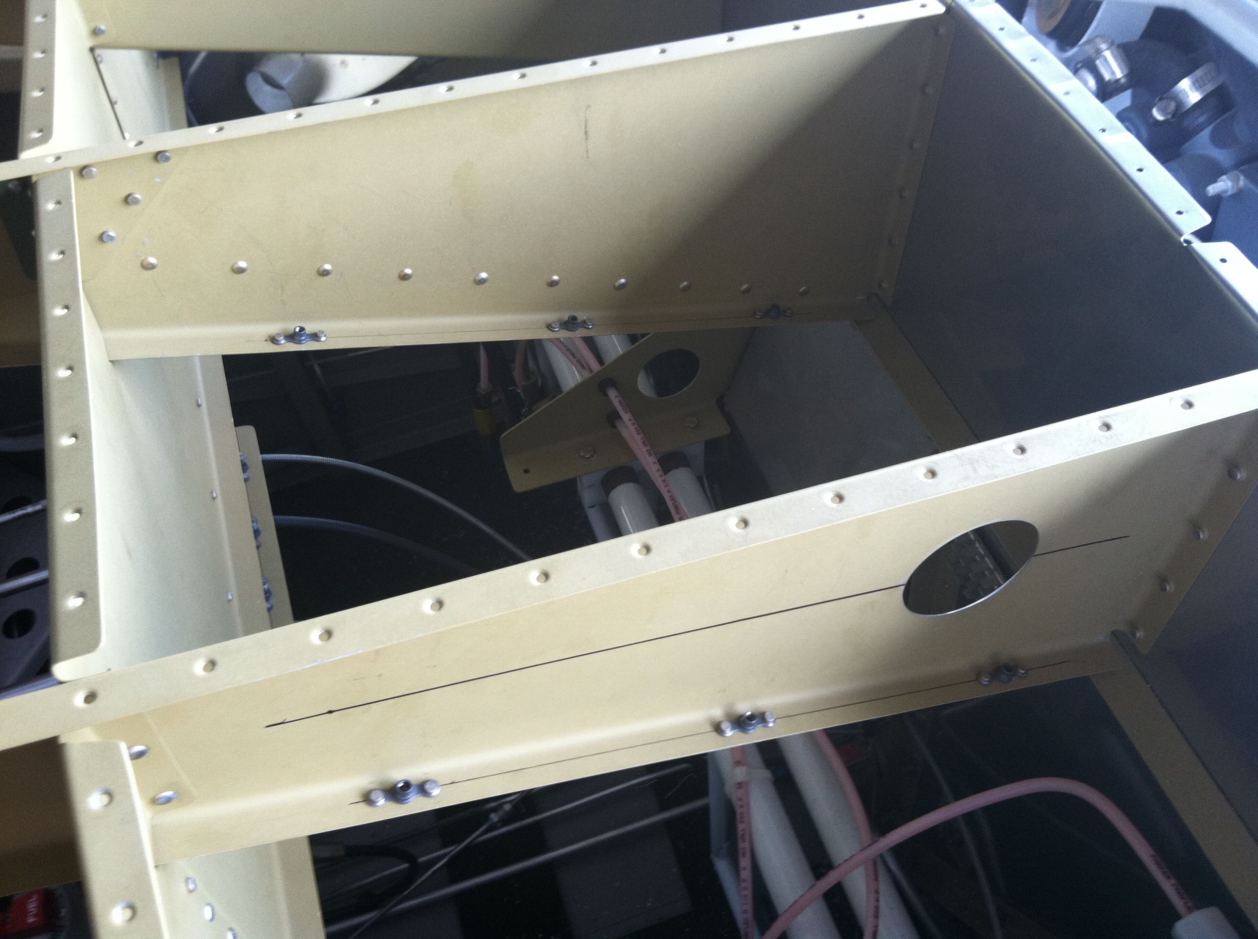
Installed nutplates on the subpanel ribs for wiring |
|
I took the advice of another building (thanks Bill R. !) and installed nutplates on each of the three ribs in the subpanel area. I put three on each bottom flange. This will allow me to use adel clamps if I need them to route wiring. I also drill a 2" lightening hole in each rib in case I need to route wires through them.
|
|
|
2011-05-27 |
Hours: 5.5 |
Category:
Firewall Forward
|
|
Manual Ref:
|
ID#:
1152
|
|
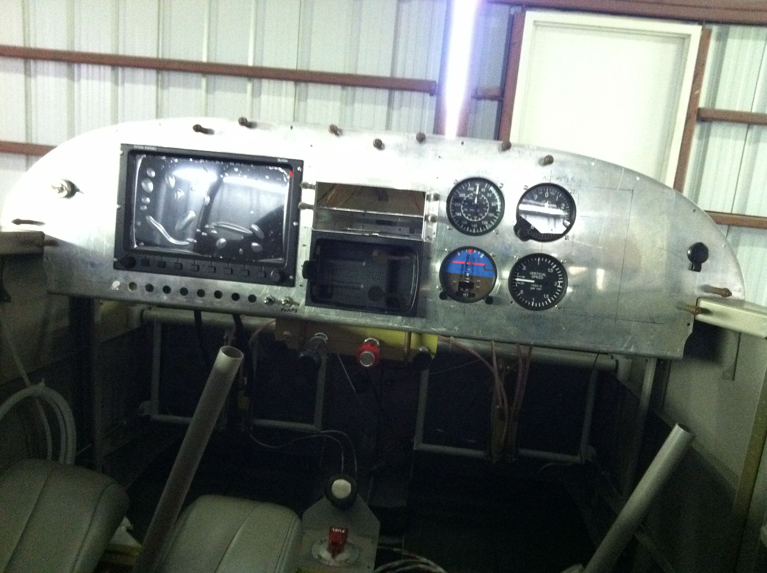
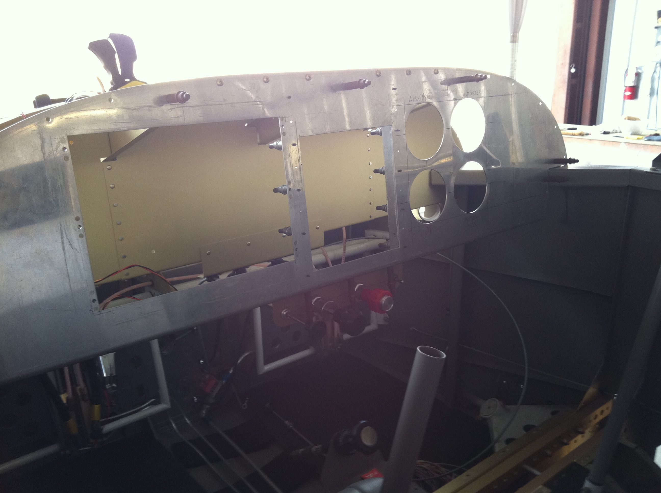
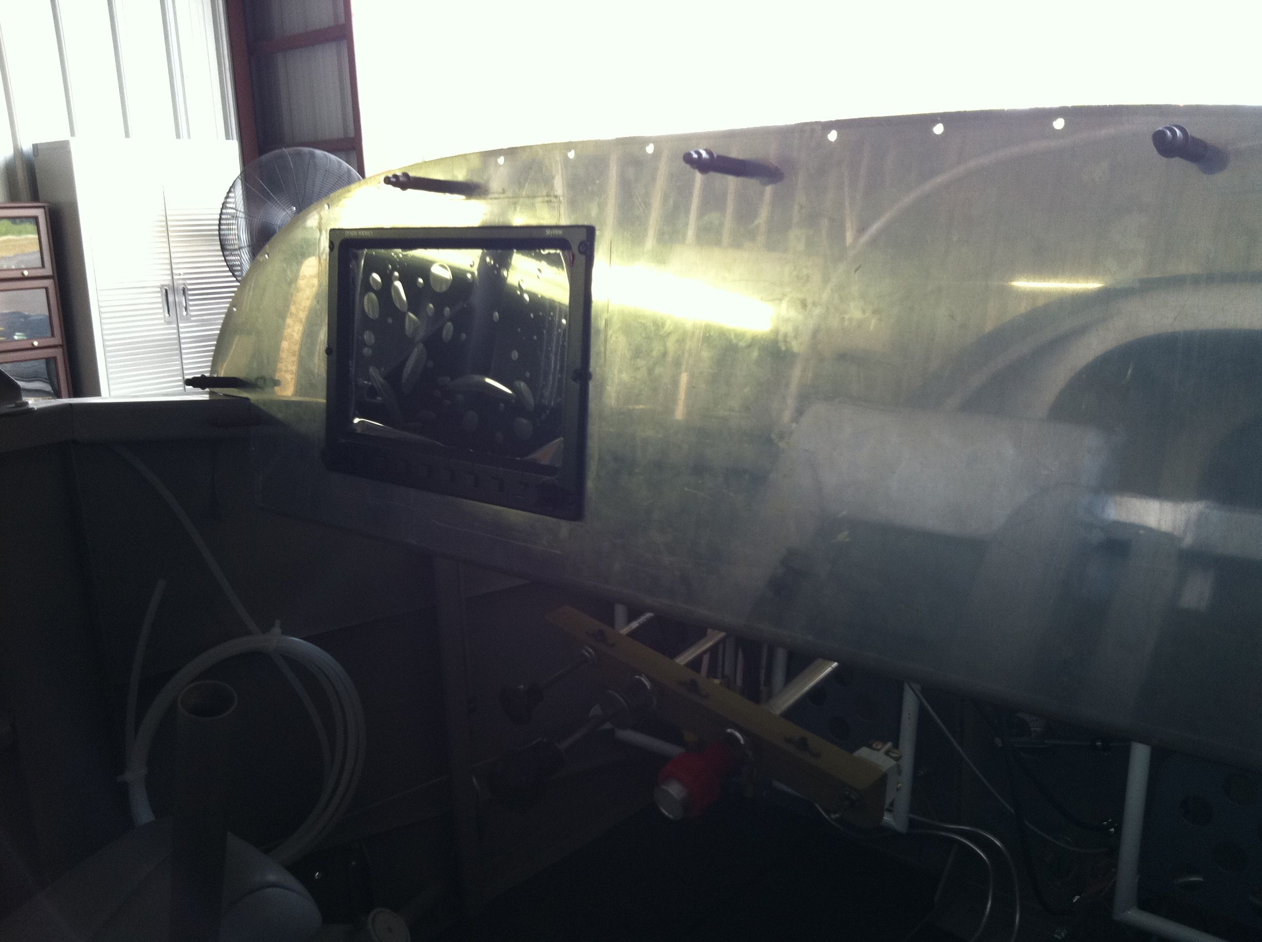
Cut a big hole in my panel for the Dynon Skyview 1000. Measure carefully several time and still screwed it up - but not too bad. A little big on the vertical (6.9") dimension. Oh well! I marked the cutout hole and then drilled four large holes, one on each side, with the unibit until it barely touched the Sharpie lines on each side. I used these holes to insert the jigsaw. With some BoeLube, the task was quite easy. Filed, deburred and sanded the edges smooth. I chose to install nutplates instead of using nuts to mount the Skyview. It will make removing the unit much easier if need be.
|
|
|
2011-05-15 |
Hours: 5 |
Category:
Firewall Forward
|
|
Manual Ref:
|
ID#:
1148
|
|
Installed the ANL fuse to the firewall and installed the wires from the shunt to the ANL and from the ANL to the started contactor buss. I had to order a new shunt because I had used another type of fastener and tightened too much and broke the bakelite base. Do not over tighten! The short run of wire from ANL to starter bussun ended up being the length of two #6 lugs back to back. I installed the ground block on the FW, then installed the battery to ground cable and the ground to engine block cable. The ground block bolt is 5/16" and I did not want to drill a hole that big in the firewall stiffener, so I reversed the orientation and used an AN3 bolt through the stiffener and drilled the 5/16" bolt hole in the firewall and backed up with a fender washer between the firewall and the ground block. There was an open boss available on the right aft side of the engine at the oil dip tube, so I used that. I worked on getting the spark plug wires secured - more to do with those.
|
|
|
2011-05-14 |
Hours: 6 |
Category:
Firewall Forward
|
|
Manual Ref:
|
ID#:
1149
|
|
Finished installing/routing the starter and alternator cables |
|
I think I am finished with routing the starter and alternator cables. I fabricated some angle mounts out of 1"x1"x1/8" angle to use in three places: a boss on the engine between the starter and alternator over the carb heat muff, an adel clamp combo on the right forward intake tube, an adel clamp combo on the right aft intake tube. I routed the alternator cable down the lower left engine mount to the shunt located on the FW there. I ran the starter cable to the starter contact, anchoring it with an adel clamp combo just below the contactor on the engine mount.
|
|
|
2011-05-13 |
Hours: 6 |
Category:
Firewall Forward
|
|
Manual Ref:
|
ID#:
1150
|
|
Installed the alternator wire |
|
Ran the alternator #6 AWG wire from the alternator to the shunt on the FW. I used a couple of aluminum angles and adel clamps to secure the cable to the engine. This took a lot of staring and head scratching.
|
|
|
2011-05-12 |
Hours: 4 |
Category:
Firewall Forward
|
|
Manual Ref:
|
ID#:
1151
|
|
Installed the shunt on the FW |
|
After much thought, I decided to mount the shunt on the right lower side of the firewall. I drilled the mount holes to 1/4" and used bolts, but tighted them too tight and broke the shunt base. I'll have to order another one. I removed those bolts and used 1/4" screws - the same type that are used to mount the baffles to the engine. They have coarse threads, so I had to obtain some nylock nuts with the correct threading. Got them a Lowes.
|
|
|
2011-04-28 |
Hours: 6 |
Category:
Firewall Forward
|
|
Manual Ref:
|
ID#:
1143
|
|
Cowl carb air inlet to FAB tunnel installed |
|
I just spent three days installing the tunnel from the front of the lower cowling back to within 1/4" of the air box per Vans instructions. I put two washers under the front two mount plate to carb bolts to lower the air box during cowl tunnel install per Vans instructions to allow for future engine sag. After finishing, I am wondering if this was a good idea. Looks like I have about 1/4" vertical difference between the tunnel and the air box inlet. Now I am wondering how the black baffle fabric will seal this. I can rivet the bottom "U" shaped piece to the air box and I suppose it will seal okay, but the seperate top piece would be just hanging up their with no forceful seal, 1/4" above the top of the tunnel. Now I am wondering if I should of ignored Vans suggestion to build for future engine sag.
|
|
|
2011-04-27 |
Hours: 5 |
Category:
Firewall Forward
|
|
Manual Ref:
|
ID#:
1145
|
|
Laid up fiberglass tunnel in the carb air inlet in the lower cowling |
|
I laid in three layers of fiberglass in the carb air inlet tunnel in the lower cowling. I cut 10" lengths of 4" wide fiberglass cut a 45 degrees per Vans instructions. I painted the foam tunnel with epoxy and then rolled one layer of fiberglass into a 1" diameter tube, inserted into the tunnel and pressed the glass against the tunnel as I unrolled it. I repeated this with two more layers, making sure the overlaps of each layer were in a different place. I pressed the fiberglass over the outer portion of the the carb air inlet on the lower cowling. I let it sit up for awhile and then put in a balloon to press the fiberglass tight against the tunnel walls. Be careful how you blow the balloon up, because the first time I tried it, the balloon was pulling the fiberglass into the hole as the balloon expanded. I filled the balloon using compressed air. Also, turn the balloon inside out first as there is an anti-sticky layer on the inside - learn them from "How It's Made" :) I used a pencil, eraser end, to push the balloon back through the hole.
|
|
|
2011-04-26 |
Hours: 5 |
Category:
Firewall Forward
|
|
Manual Ref:
|
ID#:
1144
|
|
Installed the foam block into the bottom cowl carb air inlet and carbed tunnel |
|
Installed a block of foam I bought from Hobby Lobby into the bottom cowl carb air inlet. I brushed in some epoxy to glue it into place. Let it set up firm, then installed the cowl onto the airplane. I carved out the hole to the shape of the air box inlet. This went pretty well. I just took my time. I started a hole in the center with a big drill bit, then cautiously carved away at the foam with a hacksaw blade. Once I got close to the shape of the air box inlet, I made sure the hacksaw blade touched both the cowl inlet and the air box inlet to make sure I got a smooth transition.
|
|
|
2011-04-20 |
Hours: 2.5 |
Category:
Firewall Forward
|
|
Manual Ref:
|
ID#:
1147
|
|
Assembled FAB air box and test fitted to carb |
|
I riveted the air box pieces together and installed it on the carb to see how it fit. Not too shabby!
|
|
|
2011-04-20 |
Hours: 4 |
Category:
Firewall Forward
|
|
Manual Ref:
|
ID#:
1146
|
|
The RTV finally set in the air filter after three or four days. I painted a coat of 50/50 epoxy/acetone on the inside and outside of the air box to smooth it out and fill any pin holes.
|
|
|
2011-04-16 |
Hours: 5 |
Category:
Firewall Forward
|
|
Manual Ref:
|
ID#:
1142
|
|
I sanded the inside of the fiberglass air box along the edges to smooth out where I laid in the two layers of glass yesterday. After a bunch of elbow grease expended, it turned out nicely. A big goof today. I assembled the carb heat door and scat tube flange onto the air box top plate, then riveted the whole assembly to the fiberglass air box. My last task that I have been avoiding before tackling the lower cowl inlet was to seal the filter cut out with RTV. Duh! I de-riveted the entire air box assembly so I could seal the filter per Vans instructions. I removed the carb from the engine, put mold release on the carb and the top/mount plates where needed and then applied lots of red RTV on the carb and the filter. Then I mated the two and added weight on top to seal the deal. I will trim excess RTV with a razor blade once cured.
|
|
|
2011-04-15 |
Hours: 6 |
Category:
Firewall Forward
|
|
Manual Ref:
|
ID#:
1141
|
|
FAB air box work continues |
|
Long day in the hangar. I got the carb heat door fitted and the hole in the air box top plate cut. I came up a little short on space so the carb door hinge and hose flange will all mount on top of each other at the front. I came up short on the proper compression of the filter when it is installed, so I scuffed the bottom of the fiberglass box and laid two layers of glass and finished with some leftover epoxy to get a smooth finished surface. There are some air bubbles so I will have to sand it smooth.
|
|
|
2011-04-02 |
Hours: 3.5 |
Category:
Firewall Forward
|
|
Manual Ref:
|
ID#:
1140
|
|
Drilled and clecoed the top plate to the fiberglass air box. Notched out and bent the top plate before this and double checked that the height is event with the top of the cowl inlet. I added two washer underneath the carb at the two front mount bolts per instructions to build for engine sag later on. Trimmed the fiberglass top edges even with the top plate. Drilled the mount holes through the mount plate into the top plate. One hole is too close to the edge. I think I will either relocate that hole or make a new mount plate with more material at the outer edges to allow for repositioning the mount bolt hole.
|
|
|
2011-03-21 |
Hours: 2 |
Category:
Firewall Forward
|
|
Manual Ref:
|
ID#:
1139
|
|
Filter air box mount plate fitted to carb |
|
I worked on fitting the filter air box FAB mount plate to the carburetor. The two cut outs needed to be opened up more to get the mount plate to sit flat against the carb.
|
|
|
2011-03-15 |
Hours: 3 |
Category:
Firewall Forward
|
|
Manual Ref:
|
ID#:
1138
|
|
Installed the forward control cable bracket to the sub panel |
|
Installed the forward control cable bracket on the sub panel. Test fitted the carb heat, throttle and mixture cables. Had to sit in the airplane and play with them. I think I could hear the engine revving up and cut back to an idle a few times. :)
|
|
|
2011-03-14 |
Hours: 2.5 |
Category:
Firewall Forward
|
|
Manual Ref:
|
ID#:
1137
|
|
Drilled the throttle control bracket holes for the carb heat, throttle, mixture and flap controls. Installed platenuts and mounted to the control panel.
|
|
|
2011-03-12 |
Hours: 20 |
Category:
Firewall Forward
|
|
Manual Ref:
|
ID#:
1136
|
|
Finally got baffle material riveted to the baffling |
|
I have not posted entries about baffle work for quite some time, but I have been working to finish the baffling task. I finally have the baffle material riveted to the baffles. The most aggravating part was getting the material to fit at the inlet ducts. Many hours were spent on this task that I have not logged. Keeping track of time and logging it would have been more trouble that it might have been worth as I worked over many days at odd times, off and on, between everything else going on over that last several weeks. Getting the material in place around the aft and side baffles was easy. Working it around the inlets is where the trial and error, cowling off, back on a hundred times, made logging entries not worth it. They would say the same thing every day.
|
|
|
2011-01-03 |
Hours: 2 |
Category:
Firewall Forward
|
|
Manual Ref:
|
ID#:
1134
|
|
Installed lower cowl inlet baffle strip |
|
I fabricated and installed the aluminum strip that holds the baffle material on the lower cowl inlet left side. I had done the right side some while ago. I have yet to install the baffle material on the forward center baffles.
|
|
|
2011-01-01 |
Hours: 4 |
Category:
Firewall Forward
|
|
Manual Ref:
|
ID#:
1133
|
|
Re-worked the lower baffles |
|
After some advice from a few fellow RV builders, I decided to remove the safety wire securing the lower baffles and slide sheets of silicon up between the curved parts of the lower baffles and the cylinders' cooling fins. The sheets of silicone are made from silicone uni-wrap. I cut three strips the width of the baffles and attached them together by overlapping the edges a bit. The tape sticks to itself so this worked great. I slid the "sheets" of silicone up between the baffles and the cylinder cooling fins and secured the baffles once again with .041 safety wire. It was suggested to use the red high temp RTV, but having the baffle already in place made it nearly impossible to get the RTV in there without a major mess. The 0.020" uni-wrap silicone tape is rated for 500 degrees F, so I think it will do just fine in helping to keep the cylinder cooling fins from wearing on the baffles.
|
|
|
2010-12-05 |
Hours: 2 |
Category:
Firewall Forward
|
|
Manual Ref:
|
ID#:
1132
|
|
Finished securing the lower baffles to the cylinders |
|
I finished installing the SS safety wire that secures the lower parts of the baffles to the engine cylinders. I used left over plastic brake line to separate the safety wire from the engine to keep the safety wire from wearing whatever it would have touched. The safety wire and SS "bow tie" method required a couple of tries on each set of baffle flanges. I over twisted the wire a couple of times and the wire snapped, so I had plenty of practice by the time I was done. Done? I think. We'll see what my tech advisors has to say about my creative SS "bow ties."
|
|
|
2010-11-23 |
Hours: 5 |
Category:
Firewall Forward
|
|
Manual Ref:
|
ID#:
1131
|
|
I tried to cut threads on the stainless steel rods used to tie the front and rear lower baffles securely against the cylinders. I gave up. I could not get the die to even start to cut on the rods. I decided to use stainless steel safety like some many other builders. After mulling over how to secure the wire at each end so as not to allow damage to the baffles, I decided to make some stainless steel "bow ties" out of a 1/4" strip of SS. I cut them 1 1/8" long and cut a vee notch in the middle of one edge. I threaded the safety wire through the rear hole, placed a SS "bow tie" on the baffle flange and wrapped the safety wire around the edge of the flange and ran that end of the safety wire to the front. The big trick was to figure out how to secure the safety wire in the front nice and tight. After monkeying around with this for hours, I think I figured out a good way to secure the safety wire in the front. After installing the wire in the back and pulling it up front, I twisted it with safety wire pliers to about 1/2" short of the front baffle, then ran one strand though the baffle flange hole, place the front SS "bow tie" on the front of the flange and twisted the remaining wire while pushing the front baffle onto the cylinder to make sure it is tight. This seems to have worked pretty well, but I'll get my tech advisor to check it out.
|
|
|
2010-11-11 |
Hours: 2 |
Category:
Firewall Forward
|
|
Manual Ref:
|
ID#:
1130
|
|
Made one of the reinforcing strips for the lower cowl baffle material |
|
Made the bend in the .063 strip that reinforces and anchors the baffle material to the lower cowl inlet. I made the bends and fitted it before cutting the ends off to proper length. I re-installed the lower cowling on the airplane and test fitted some material in place to see how it fits.
|
|
|
2010-11-10 |
Hours: 2.5 |
Category:
Firewall Forward
|
|
Manual Ref:
|
ID#:
1129
|
|
More baffle material install |
|
Installed the rest of the baffle material around the side and aft baffles. Not sure it is correct. I'll get someone who know what they are doing to look at it.
|
|
|
2010-11-08 |
Hours: 2.5 |
Category:
Firewall Forward
|
|
Manual Ref:
|
ID#:
1128
|
|
Started installing the baffle material |
|
After looking at a few local RVs' baffle jobs, I decided to try installing the material on mine. I cut strips of 3" off the roll of black material that came with the baffle kit and fitted and cut them as best I could. I pre=drilled a rivet pattern on the baffles first, then held the material in place. Being extra careful not to drill holes in my fingers, I drilled through the baffles into the material and clecoed from the inside to hold the material in place.
|
|
|
2010-11-06 |
Hours: 2 |
Category:
Firewall Forward
|
|
Manual Ref:
|
ID#:
1127
|
|
Installed the mag blast tubes |
|
I drilled 11/16" holes in the aft baffles for the mag blast tubes and installed the corrogated tubes, tie-wrapping them as needed to get them to point at the mags. Not sure if the blast air should strike the mags at any particular place. Also installed the AN fittings on the oil cooler and installed the oil hoses. Starting to get crowded between the firewall and aft baffles.
|
|
|
2010-11-04 |
Hours: 3.5 |
Category:
Firewall Forward
|
|
Manual Ref:
|
ID#:
1126
|
|
More oil cooler installation |
|
I removed as much of the inboard aft flange of the oil cooler as I felt I should to allow clearance from the engine mount. It is only a little more that 1/4" clearance. Not sure what can be done. Perhaps I will move the bolt down about 3/4" and drill another set of holes in the oil cooler and install another platenut in the aft baffle because the bolt head in the center location will give less clearance. Then I can install another bolt through just the foreward flange like the top bolt is installed. Still, the flange of the oil cooler is much less that the 1/2" clearance needed according to the plans. I also drilled a third mounting hole and installed another bolt on the outboard side.
|
|
|
2010-11-03 |
Hours: 2 |
Category:
Firewall Forward
|
|
Manual Ref:
|
ID#:
1124
|
|
Started installation of the oil cooler. I thought this would be a breeze, but like any airplane building task, it just cannot be simple. It seems the aft inboard flange of the oil cooler will interfere with the engine mount. I trimmed enough of a scallop out of the flange to at least get the oil cooler mounted to the aft baffle. Not sure if I will get the 1/2" clearance from the engine mount that Vans says I need. I also had to scallop out some of the fore inboard oil cooler flange because the ignition wire baffle seal would interfere otherwise.
|
|
|
2010-11-01 |
Hours: 3 |
Category:
Firewall Forward
|
|
Manual Ref:
|
ID#:
1123
|
|
Finished riveting the baffles |
|
Finished riveting the baffles at the aft corners. I had to get creative with ways to get the rivets bucked. I am not sure if this could have been done off of the engine as I never tried to install the aft baffles with the rear side baffles clecoed on. I would suggest giving it a try to see if you can rivet these off of the engine and then install. It would have been much easier. I reinstalled the oil return line and put the grommet in place at the right ramp baffle. Next up is installing the baffle material and oil cooler.
|
|
|
2010-10-31 |
Hours: 5.5 |
Category:
Firewall Forward
|
|
Manual Ref:
|
ID#:
1122
|
|
Primed and painted all the baffling today. I used high temp engine paint. It was a bit breezy so the paint job is less than excellent and I am certain that most of the paint from the spray can went away with the wind. But it came out okay. I did not realize how bright white the finished job would look...WHITE! I began riveting the aft to rear side baffles together in place on the engine. I did not realize how difficult this would be. The squeezer will not reach most since the engine mount gets in the way. Same with the rivet gun - tight area to work in. I riveted the clips on each side that connects the fore and aft side baffles. After butchering several rivets on each of the aft corners, I quit for the day.
|
|
|
2010-10-30 |
Hours: 4.5 |
Category:
Firewall Forward
|
|
Manual Ref:
|
ID#:
1121
|
|
Baffles in the aft left corner |
|
I decided to fabricate a clip to reinforce the oil cooler brace with the #4 cylinder baffle. The originally shaped oil cooler brace, after trimming the contoured curve of the upper cowling, left too little a flange to properly rivet to the #4 cylinder baffle. I use some .040 angle material left over from fabricating the #4 cylinder to left aft baffle reinforcing angle. It is an odd shaped clip but should work okay. Primed a bunch of baffle parts and then riveted most of them together. I riveted the oil cooler brace and reinforcement plate to the aft left baffle, then riveted the clips to the oil cooler brace. Riveted my reinforcing angle to the #4 cylinder baffle and then riveted on the .063 angle that reinforces the #4 cylinder baffle. I reinstalled everything and drilled and clecoed the little clips on either side that connects the fore side and aft side baffles. I think that the next thing to do is to removed all the baffles, prime and paint them. Then it is time to install the baffles for the last time - I think.
|
|
|
2010-10-29 |
Hours: 5 |
Category:
Firewall Forward
|
|
Manual Ref:
|
ID#:
1120
|
|
More baffle work at the oil cooler |
|
Cut the hole in the left aft baffle for the ignition wires. Installed the oil cooler brace. I wish Vans had not predrilled all the holes in the flanges as it made it difficult to work with, particularly on the left side up against the left #4 cylinder baffle; the two rivets will interfere with rivets from the stiffener on the #4 cylinder baffle. So I decided to removed the flange that points downward. I made a clip that I will rivet to the upper side of the brace against the #4 cylinder baffle. I cut the oil cooler brace down to mimic the curve of the aft baffle by marking the aft baffle curve on a piece of cardboard and transferring the pattern to the oil cooler brace. After trimming, there was little left of the flange on the oil cooler brace that points forward and would normally be riveted to the #4 cylinder baffle. I may make another clip to reinforce this area. I also fabricated a .040 angle to reinforce the angle area where the #4 cylinder baffle connects to the left aft baffle. Hope this will ward off an cracks that I have seen other folks have problems with in this area.
|
|
|
2010-10-28 |
Hours: 1.5 |
Category:
Firewall Forward
|
|
Manual Ref:
|
ID#:
1119
|
|
Worked on oil cooler baffles |
|
Marked and cut the hole in the aft left baffle for the oil cooler. Positioned the oil cooler bracket on the aft baffle and drilled and clecoed the rivet holes.
|
|
|
2010-09-30 |
Hours: 3.5 |
Category:
Firewall Forward
|
|
Manual Ref:
|
ID#:
1117
|
|
Finally got the cowling to fit over the baffles |
|
After 30 or 40 times of putting the cowling on, marking the baffles, removing the cowling, trimming the baffles, repeat, repeat, repeat - the upper cowling finally fits! Yeah! I used some paper clips places upright on the baffles to help me mark the baffles for the final trim gap of 3/8" to 1/2". I placed them side by side to keep them from falling over while placing the cowling back on. I only had a box of 100 paper clips so I had to do this three times to make the mark all the way around the baffling.
|
|
|
2010-09-28 |
Hours: 3 |
Category:
Firewall Forward
|
|
Manual Ref:
|
ID#:
1116
|
|
Another round of monotonous trimming the baffles to get the upper cowling to fit. Getting closer. The pictures I took did not come out for some reason. More later...
|
|
|
2010-09-27 |
Hours: 3 |
Category:
Firewall Forward
|
|
Manual Ref:
|
ID#:
1115
|
|
Yet more interations of putting the top cowling on, checking and marking where the baffles interfere, removing the cowling, trimming the baffles and repeat, many, many times. Sure removed a bunch from the front side baffles where the inlet ducts are.
|
|
|
2010-09-24 |
Hours: 2 |
Category:
Firewall Forward
|
|
Manual Ref:
|
ID#:
1114
|
|
Began trimming the baffles to fit the upper cowling |
|
I began trimming the baffles down so the upper cowling will fit. Not sure what I was doing, but I just started by putting the cowling on as best as I could, observing where the baffles interfered, marked and trimmed them. Repeated a dozen times before I called it quits. Long way to go on this task. The plane looks like it is smiling with the upper cowling in place..
|
|
|
2010-09-22 |
Hours: 4.5 |
Category:
Firewall Forward
|
|
Manual Ref:
|
ID#:
1113
|
|
Riveted the right side conical piece to the baffles |
|
Drilled the rivet patterns in the right side air ramp and forward side baffles. Primed the parts. Riveted the right side air ramp and forward side baffles together, then riveted the conical piece to both baffles. Started working on the left side conical piece. I spent a few hours trying to form the piece. Not as lucky as before with the right side one. This one is more difficult perhaps because it is a longer piece.
|
|
|
2010-09-21 |
Hours: 2 |
Category:
Firewall Forward
|
|
Manual Ref:
|
ID#:
1112
|
|
Riveted the clips to the forward and air ramp baffles |
|
Primed all the clips and riveted them to the forward and air ramp baffles. Some of these rivets were difficult to get to with the squeezer. I had to buck a couple of them.
|
|
|
2010-09-20 |
Hours: 3.5 |
Category:
Firewall Forward
|
|
Manual Ref:
|
ID#:
1108
|
|
Made the clips to attach forward baffles to air ramp baffles |
|
Finished trimming the forward baffles to fit against the air ramp baffles nicely. Made the three clips that attach the forward baffles to the air ramp baffles. Formed and trimmed them to fit well, drilled and clecoed into place. Removed everything and deburred. Drilled rivet pattern in the right conical piece. Still need to form the left conical piece.
|
|
|
2010-09-19 |
Hours: 5.5 |
Category:
Firewall Forward
|
|
Manual Ref:
size=8
|
ID#:
1107
|
|
Air ramp and forward baffle work |
|
Made the bends in the #1 and #2 forward side baffles to form the flange that supports the CB-902A and CB-910A air ramp baffles. More work on the front baffles to get them to fit without forcing down the air ramp baffles. Formed the right side conical piece that attaches the outboard air ramp baffle to the #1 cylinder side baffle.
|
|
|
2010-09-18 |
Hours: 5 |
Category:
Firewall Forward
|
|
Manual Ref:
|
ID#:
1109
|
|
Riveted the air ramp stiffeners |
|
Fitted, drilled and riveted the support pieces under the left side air ramp baffle that attaches to the engine with the big screws. Riveted that assembly to the air ramp. The middle hole that plans say to leave open for now will also be riveted to the clip piece that connects the forward and air ramp baffles a few steps later. Riveted the air ramp stiffeners, engine braces, and clips to the air ramp baffles.
|
|
|
2010-09-14 |
Hours: 4 |
Category:
Firewall Forward
|
|
Manual Ref:
size=8
|
ID#:
1106
|
|
Started trimming on the CB-902A and CB-910A ramp baffles |
|
Got brave and started fitting and trimming the CB-902A and CB-910A ramp baffles. You cannot really get the lower cowling in place, but pull it up as close as possible and eyeball where you need to trim the ramps. Trim a little, reinstall, put the lower cowling on, mark for trimming, remove cowling, remove ramps, trim a little and do it all over again and again.
|
|
|
2010-09-10 |
Hours: 2.5 |
Category:
Firewall Forward
|
|
Manual Ref:
|
ID#:
1105
|
|
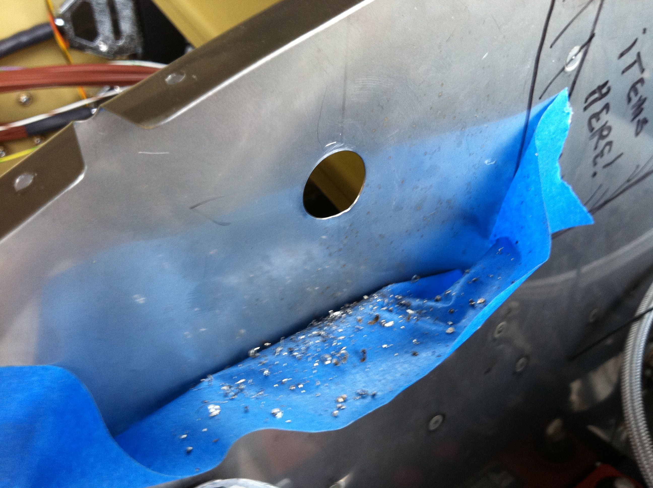
Installed one ignition wire pass thru in the aft baffle |
|
Installed the right side ignition wire pass thru on the right side aft case baffle. Used the unibit to cut two holes and trimmed the excess off to make the hole in the baffle. The distance between the two holes is 11/16" and enlarged to 7/8" in order to allow the sparkplug nut on the end of the ignition wire to pass through. Lined the passthru screw holes up on a previously marked centerline then drilled to #12. Did some other misc. baffle work as well.
|
|
|
2010-09-09 |
Hours: 4 |
Category:
Firewall Forward
|
|
Manual Ref:
|
ID#:
1104
|
|
Ramp assembly baffle work |
|
Assembled and test-fitted the right side ramp parts. I drilled the 1" hole through the stiffener and ramp part hoping that it would line up with the constant speed prop oil line. I unhooked the oil line from the engine to allow me to work the ramp into place. After clecoing and bolting the right ramp assembly into place on the engine, the oil line does indeed go right through the hole almost dead on center. I cut the grommet with a razor and installed it in the hole around the oil line. Looks like this is a good fit! Next up - time to bend and trim the forward area of the baffles to fit the cowling.
|
|
|
2010-09-08 |
Hours: 6 |
Category:
Firewall Forward
|
|
Manual Ref:
|
ID#:
1103
|
|
Long baffle day in the heat |
|
A long day in the hot hangar today. A bunch of baffle work. Trimmed some off the lower inboard edge of the right aft case baffle to allow it to fit better without having to force it into place. Removed and trimmed a little at a time. After about five iterations of removing and trimming and reinstalling, it fits much better. Installed the after and forward support brackets that are bolted onto the engine. I primed and painted these two parts, but the aft one got scratched up from installing and removing the right aft case baffle so much. Deburred and edge smoothed the ramp parts. Assembled the left ramp parts and test-fitted it on the engine. Seems like a lot of time with little gain today - but that's building airplanes!
|
|
|
2010-09-07 |
Hours: 4 |
Category:
Firewall Forward
|
|
Manual Ref:
|
ID#:
1102
|
|
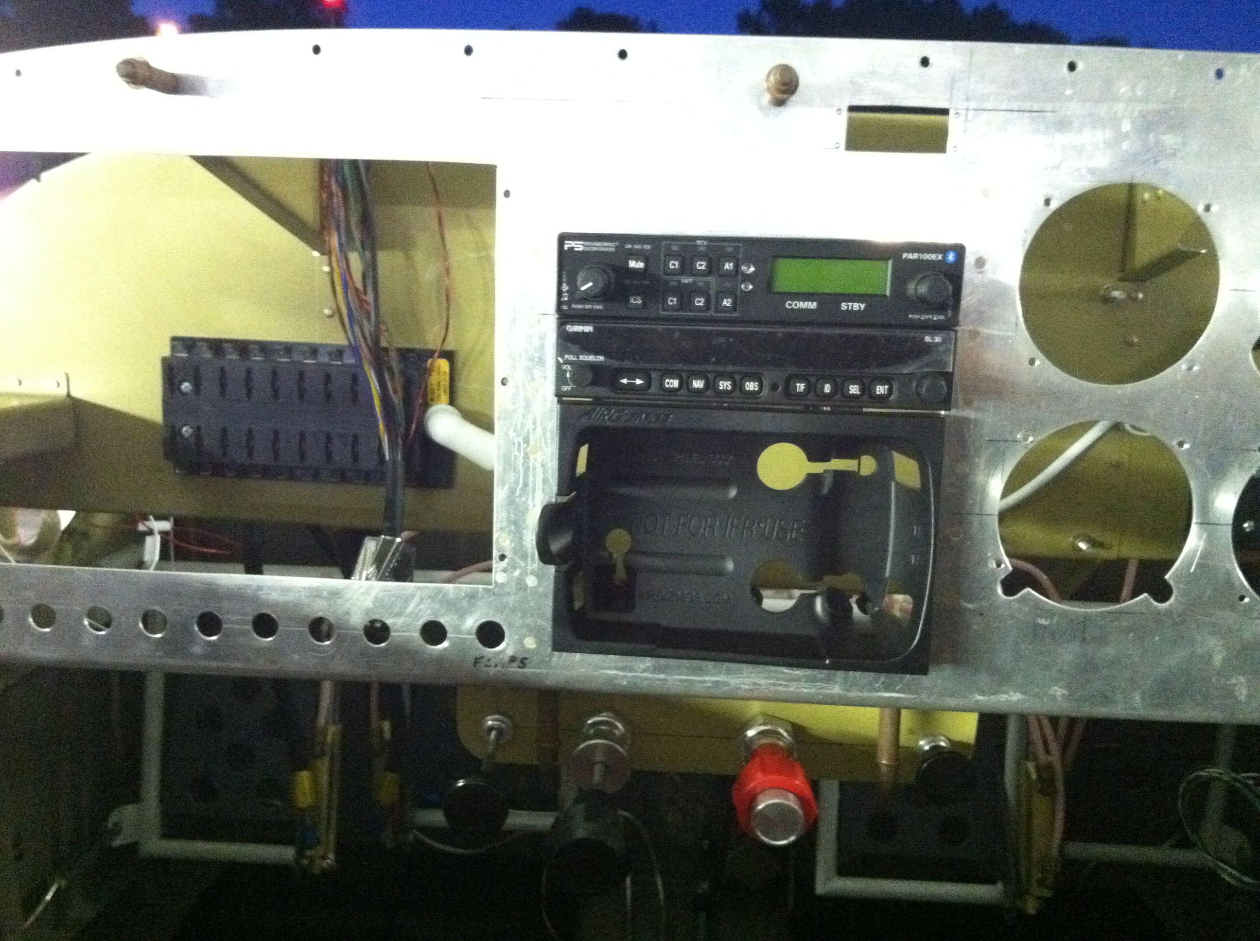
Got the cylinder 1 and cylinder 2 baffle assemblies installed. It is all test fitted, not final. I had to remove the oil stick tube to get the MX35206-281 screw installed in right side aft panel to engine block. I cut the CB-706B spacer to 7/8". Once installed it seems to be too short. After tightening the bolt, the tab on the bottom of the CB-906A left aft case baffle bends against a cylinder bolt. This does not look right. The bolt for this was not called out on the plans - I used the only AN4 bolt I could find in the bags that came with the baffle kit.
|
|
|
2010-09-05 |
Hours: 4 |
Category:
Firewall Forward
|
|
Manual Ref:
|
ID#:
1100
|
|
More engine baffle work. Lots of edge deburring an smoothing. The plans that come with the baffle kit are nice, but confusing because almost immediately they have you installing the oil cooler related items but then say you may want to wait until the baffles are installed to locate the oil cooler. Okay! Also, you have to be careful of the things that the plans say to rivet together early - you may have trouble installing the pieces later, so you really need to read ahead and plan ahead to avoid pitfalls.
|
|
|
2010-09-04 |
Hours: 5 |
Category:
Firewall Forward
|
|
Manual Ref:
|
ID#:
1101
|
|
Started "exploring" the engine baffle kit. Looks to be very nicely done with all the shaped parts and such. Cut some parts out and did a bunch of edge smoothing and deburring. Long day!
|
|
|
2010-09-01 |
Hours: 5 |
Category:
Firewall Forward
|
|
Manual Ref:
|
ID#:
1099
|
|
Exhaust bracing installation |
|
Wrestled with the exhaust bracing installation. With the cowling installed, I positioned the exhaust pipes even distances from the engine mount and the cowling. I slide the huge exhaust clamps up the pipes first, the I put spacers between the exhaust and the engine mount and secured temporarily with tie wraps. I removed the cowling and sat there for awhile trying to figure out how to proceed. I determined that I must get the cross member installed first. I positioned the exhaust pipe clamps on each side so the flat flange is faciing side up, then measured the distance between the two clamps' bolt holes. I cut enough off each SS tube piece so that the assembly fit. I had to use 3/4" spacers on each side to raise the cross member enough to clear the mixture cable. After the cross member was securely installed, I installed the two assemblies that attach to the engine sump bolts. These were too long to start with as well, so I removed the lower piece of SS tubing and cut off some to make it line up with the bolt holes in the exhaust pipe clamps. The real cuss was to get the washer and nut on these bolts. I used big pliers to squeeze the clamp together to get the bolt fastened. A better idea was brought up to me after I was done: use safety wire and safety wire pliers to squeeze the clamp together. Great idea Tom! I'll have to remember that when working on tough adel type clamps in the future.
|
|
|
2010-08-31 |
Hours: 3.5 |
Category:
Firewall Forward
|
|
Manual Ref:
|
ID#:
1098
|
|
Laid up some little squares of BID cloth on the inside lower corner of the bottom cowling between the vertical and horizontal hinges. This area needs shaving on the outside as it sticks out and does not form a nice transition from the cowling to the fuselage. I laid up 5 layers. After setting up, I trimmed the edge and sanded smooth and reinstalled the cowling on the airplane. It looks as though I will need to add a few more layers once I sand the corner even with the fuselage. Also installed the platenuts and screws in the cowl halves at the spinner.
|
|
|
2010-08-29 |
Hours: 3.5 |
Category:
Firewall Forward
|
|
Manual Ref:
|
ID#:
1097
|
|
Installed cowl ducts and hinge pin anchors |
|
Sanded the areas of the cowl ducts and the upper cowling where they would bond together. Then mixed up some epoxy and painted the bonding areas on both the cowl ducts and the upper cowling, then clecoed the cowl ducts to the upper cowling, put the cowling back on the airplane to set up overnight. Also cut some hinge pieces to anchor the upper/lower cowling hinge pins to the front of the cowling per plans. I drilled holes through the firewall so the hinge pins will go through.
|
|
|
2010-08-28 |
Hours: 4 |
Category:
Firewall Forward
|
|
Manual Ref:
|
ID#:
1096
|
|
Epoxied the inside of the cowling halves |
|
Mixed up a 50/50 solution of epoxy and acetone and painted the insides of the cowling halves with two coats. Each coat dried to touch in about two hours. I put the cowling back on the airplane to set up over night.
|
|
|
2010-08-18 |
Hours: 2.5 |
Category:
Firewall Forward
|
|
Manual Ref:
|
ID#:
1095
|
|
Did some tweeking on the lower cowling support bracket. Removed it and trimmed some excess metal off where it meets the engine mount gusset. It was easier getting the bracket back on without the lower cowling in place. I cut the bottom hinge pins to length and bent them to fit. To do this I first inserted the pins in the hinges and marked where they should bend, removed them and bent them with a hammer with the pin in the table vice. I also starting mulling over the installation of the inlet ducts. Looks like fun ahead!
|
|
|
2010-08-16 |
Hours: 4.5 |
Category:
Firewall Forward
|
|
Manual Ref:
|
ID#:
1094
|
|
Bottom cowling support bracket work |
|
Managed to get the bottom cowling support bracket (or what ever it is called) assembled. This was like putting a puzzle together. The trickiest part is getting the bend correct on the part that connects to the engine mount gusset. Had to call it quits early, so I hope to finished this tomorrow.
|
|
|
2010-08-15 |
Hours: 3 |
Category:
Firewall Forward
|
|
Manual Ref:
|
ID#:
1093
|
|
Trimmed the extra fiberglass from the exhaust recess area so it is even with the rest of the bottom aft edge. Since my slot for the nose gear is wider, I had to make the pieces for the support structure from stock material. Not much to show for the time I spent today.
|
|
|
2010-08-14 |
Hours: 4.5 |
Category:
Firewall Forward
|
|
Manual Ref:
|
ID#:
1092
|
|
Riveted the hinges on the bottom cowling and installed oil access door |
|
I finished up riveting the hinges today. I got all six hinge pieces riveted to the bottom cowling. I also installed the oil access door. Locating the door latch hardward on the cowling was a bit tricky. Not a lot of margin for placement as the aft one might interfere with the thicker part of the cowling if placed to far aft. Also, make sure to install the latches so the little butterfly handles are oriented fore to aft when latched to reduce drag.
|
|
|
2010-08-13 |
Hours: 4 |
Category:
Firewall Forward
|
|
Manual Ref:
|
ID#:
1091
|
|
Riveted the hinges on the upper cowling |
|
Riveted the hinge pieces on the upper cowling. I mixed up some epoxy and microballoons to help secure the hinges. This was a little messy but not a bad task. Once I had all four hinges rivets on, I put the cowling back on the airplane to let it cure overnight.
|
|
|
2010-08-11 |
Hours: 4 |
Category:
Firewall Forward
|
|
Manual Ref:
|
ID#:
1090
|
|
Drilled upper cowling side hinges |
|
Drilled the upper cowling side hinges. Also made new hinge pins for the lower cowling to firewall four hinge pieces. The ones I had were aluminum. I found two lengths of steel hinge pin and realized that the instructions said to use the steel ones, not the aluminum ones that came with the hinges. I think I am ready to start mixing epoxy and microballoons and do some riveting!
|
|
|
2010-08-10 |
Hours: 4.5 |
Category:
Firewall Forward
|
|
Manual Ref:
|
ID#:
1089
|
|
Lower cowling trimmed along the sides |
|
Long hot day! I trimmed the flanges from the upper edge of the lower cowling. Checked the fit to the upper cowl and adjusted a few areas. The fit looks good. I drilled the hinges to the bottom cowling and ground out the area near the front so the hinge pins could be inserted. Drilling and clecoing the hinges took some thought. It goes from centered eye at the fore to eye above edge at the aft, so you have to consider edge distance when drilling the hinge as it changes from too high to too low fore to aft. I marked a line along the edge of the lower cowling fore to aft about 23/64". This allow my best chance to stay within edge distance as I drilled the hinge from aft to fore. I also riveted in a short piece of mock hinge on each side of the fuse/firewall above the hinge that joins the upper and lower cowls and up to where the side and top skins join. This will keep the cowling in that area from being pushed. I used an .020 shim and some .040 to mimic the hinge for this. The pieces only covered three rivets, so they were only about 2 3/4" long.
|
|
|
2010-08-09 |
Hours: 4.5 |
Category:
Firewall Forward
|
|
Manual Ref:
|
ID#:
1088
|
|
Moving right along on the cowling |
|
A long productive day. I got the lower cowling aft edges trimmed to fit, then riveted on the bottom and side hinges. I used a strap clamp to hold the upper and lower cowling halves together nice and tight while working at this stage. I drilled and clecoed the upper cowl hinge rivet holes. I marked the cut line along the upper and lower cowling overlap fore and aft trim line. Everything is drilled and clecoed except the fore to aft hinges that connect the upper and lower halves. I removed the 1/4 plexiglass spacer from between the upper cowling and spinner to see the result. It is really tight! About 1/8", so I was surprised that it didn't come out to the 1/4" space that I thought I was building into the set up. The space at the bottom is almost 5/16". I will wait until after I have the engine running to see if I need to work the spinner area of the cowling for a nicer fit.
|
|
|
2010-08-08 |
Hours: 2.5 |
Category:
Firewall Forward
|
|
Manual Ref:
|
ID#:
1087
|
|
Had to remove more material from the right side of the slot in the bottom because the nose gear leg is close on that side when the lower cowling was taped into place on the airplane. I cut the overlap material from the aft edge of the lower cowling to around the curve. Now only the sides need trimming at the aft edge. I think I'm getting close!
|
|
|
2010-08-07 |
Hours: 3 |
Category:
Firewall Forward
|
|
Manual Ref:
|
ID#:
1086
|
|
Upper and lower cowling fitting at the spinner |
|
After talking with a few RV builders now flying about how to proceed with matching up the cowling halves at the spinner, I decided to just start hacking with the cutoff wheel. Yikes! I removed the front and interior flange at the spinner from the lower cowling, leaving only the flange that will hold the nutplates to hold the two halves together. After some other trimming, I got the halves clamped together, making sure they are on the same plane at the spinner, and drilled #40 holes and clecoed them together. After fitting on the airplane, it seems the lower cowling wants to pull the upper cowl off a bit - I thought I had it fitted perfectly. Plenty of tweaking still ahead.
|
|
|
2010-08-06 |
Hours: 2 |
Category:
Firewall Forward
|
|
Manual Ref:
|
ID#:
1085
|
|
Test fitted the lower cowling and marked the aft edge cut line - not alot of overlap to start with compared to the upper cowling. Had to cut another 1/4" of material from the right side of the nose gear slot as the cowling rubbed up against the nose gear leg when fitted into place. I have gotten the spinner area matched up on the two cowling halves yet. Need to do that to continue on.
|
|
|
2010-08-05 |
Hours: 5 |
Category:
Firewall Forward
|
|
Manual Ref:
|
ID#:
1084
|
|
Lower cowling hings installed on firewall |
|
Installed the lower hinges on the firewall. Cut the slot in the lower cowling for the nose gear. Had to pretty much eyeball where the middle was to mark and cut the slot. After test fitting it to the airplane, I will have to cut about another 1/4" off the right side of the slot as the cowl rubs the gear leg as is. Still need to get the upper and lower cowlings to fit at the spinner.
|
|
|
2010-08-04 |
Hours: 1.5 |
Category:
Firewall Forward
|
|
Manual Ref:
|
ID#:
1083
|
|
Started on the lower cowling |
|
Tried to modify the lower cowling to get it and the upper cowling to fit together at the spinner. Some modification will definitely be required. I removed the flange from the outer part of the air intakes to get the fit. Some material will have to be removed from the underside of the upper cowling to get them to fit together nicely. A lot more work to get this task done.
|
|
|
2010-08-03 |
Hours: 2.5 |
Category:
Firewall Forward
|
|
Manual Ref:
|
ID#:
1082
|
|
Got the upper cowling hinges done and trimmed the aft edge of the upper cowling |
|
Got the two hinges along the upper cowling/top fuse skin done. Bevel the cowling hinge pieces and deburred them. Also trimmed the aft edges of the upper cowling to fit nicely. There is a 1/16 or less gap between the top fuse skin and the upper cowling to allow for paint.
|
|
|
2010-08-02 |
Hours: 2 |
Category:
Firewall Forward
|
|
Manual Ref:
|
ID#:
1081
|
|
Drilled and clecoed the upper cowling hinges |
|
Drilled the upper cowling hinges to the fuse/firewall. Removed them and dimpled the .032 shims and countersunk the hinges.
|
|
|
2010-07-31 |
Hours: 3.5 |
Category:
Firewall Forward
|
|
Manual Ref:
|
ID#:
1080
|
|
I positioned the upper cowl to where it is level with the airplane, marked a few reference points so I could get it back into that position. I marked the aft cut line and cut that off with the cutoff wheel. Sanded the edge smooth. I drilled and clecoed the right side length of hinge along the top fuse/firewall.
|
|
|
2010-07-30 |
Hours: 3 |
Category:
Firewall Forward
|
|
Manual Ref:
|
ID#:
1079
|
|
Cut oil filler door hole in upper cowling |
|
I cut the oil filler door opening in the upper cowling. Smoothed the edges first with a file, then will some really fine grain sand paper. Edges are as smooth as glass. Sized the oil filler door to fit and did some re-working on the hinge pieces to get them to fit better. I removed the aft tab on the cowl side hinge piece that I had left on their for more mounting area because it interferred with an area of thicker cowl nearby. Made some .040 shims for each hinge piece to help lower the profile of the hinge eyes. Did some more head scratching and studying before trimming the aft edge of the upper cowling. I want to make sure the upper cowl is level before marking the aft edges for trimming.
|
|
|
2010-07-29 |
Hours: 3 |
Category:
Firewall Forward
|
|
Manual Ref:
|
ID#:
1078
|
|
Marked the 2" line around the firewall on the top, sides, and bottom fuse skins. Cut the oil door to size and cut the hinge to fit. I marked the cowling for the oil door cutout. Placed the cowling on the airplane using the spacer tool Tom lent to me to get the proper 1/4" spacing between the cowling and the spinner aft bulkhead.
|
|
|
2010-07-26 |
Hours: 2 |
Category:
Firewall Forward
|
|
Manual Ref:
|
ID#:
1077
|
|
Assembled battery and ground cables |
|
Assembled the positive terminal battery cable. Crimped the lugs on each end. Test fitted to the firewall. Not sure where I will anchor my negative cable yet, so I only put one lug on it so far.
|
|
|
2010-07-21 |
Hours: 2.5 |
Category:
Firewall Forward
|
|
Manual Ref:
|
ID#:
1076
|
|
More firewall forward tinkering |
|
I think I have the Red Cube fuel flow transducer install, so now on to something else. I did a lot of head scratching and tinkering about, reading the manual and looking at the engine. A lot yet to do! I went ahead and torqued the exhaust pipe flange bolts. I do not think I will be removing the exhaust system again. I had to loosen the EGT sensor probe pipe clamps in order to get the socket on the nuts. I used a universal joint type extension to get to them and torqued them to 12.5 foot pounds. Next I safety wired the oil dip stick tube to the engine block. I pulled the throttle and mixture cables off the shelf and noticed some rubber boots on were cracking and splitting. Yikes! Shelf wear? I fellow builder told me not to worry about it, his fell off along time ago - not an issue. Still not cool though.
|
|
|
2010-07-20 |
Hours: 2.5 |
Category:
Firewall Forward
|
|
Manual Ref:
|
ID#:
1075
|
|
Finished a fuel hose and installed the tach sending unit |
|
Installed the UMA tach sending unit into the left mag with the help of Ron Shelton - glad he dropped by! The thing is rather difficult to install and Ron helped unwind the wiring as I turned the wrench. Thanks Ron! Then I moved on to finish making the fuel hose that goes from the fuel pump to the Red Cube fuel flow transducer. I had to cut the fire sleeve a bit and re-dip that end, clamped it on with some Aeroquip clamps (ACS PN: 900591B-1C). Removed the exhaust pipes enough to place the carb heat muff onto the exhaust pipe. Other misc. tinkering as well.
|
|
|
2010-07-17 |
Hours: 3.5 |
Category:
Firewall Forward
|
|
Manual Ref:
|
ID#:
1074
|
|
I had to make my own fuel hose that goes from the fuel pump to the Red Cube fuel flow transducer. The length of SS braid (816) fuel hose was 8.875". Van's pre-made hoses are too long. As with anything else to do with the project, I was completely unknowledgable about doing this. So I delved in, bought the parts from Vans. I installed a fitting on one end of a length of SS braided fuel hose and installed this on the fuel pump fitting. I worked the fuel hose over to the Red Cube and marked a cut line. I wrapped masking tape around the fuel hose several layers nice and tight and centered on my cut line. I put this in the table vice, clamping only enough to hold the fuel hose snuggly and cut the fuel hose with the cutoff tool - the same one I cut the canopy with. The masking tape keeps all the SS braiding from getting out of control. I removed the tape and installed the other fitting. I cut a length of fire sleeve about 3/4" longer that the length I measure off the new fuel hose assembly. This will help accommodate the radius bend from the fuel pump to the Red Cube fuel flow transducer. To seal the ends of the fire sleeve so they will not soak up oil, fuel, and debris, I made a batch of dip: I filled a baby food jar half way with MEK (used air mask) and then squeezed in about a foot long drop of red high heat Permatex RTV. This was really experimental. I had to mix this for about 15 minutes to get all the RTV to dissolve into solution. The consistency was like tomato soup or perhaps slightly thicker. Once mixed I dipped the ends into the jar, swirling around gently and holding it in there for about 10 seconds or so to make sure the fiber lining in the fire sleeve soaked up ample dip solution. Once removed I let the excess drain out onto some card board with gentle shakes. I repeated the dipping process for the other end and let cure for about 45 minutes and then repeated the dipping process. This seems to have worked really well. The fire sleeve ends are sealed very well and there is enough flex to installed the fuel hose. I practiced clamping the ends with Aeroquip strap clamps but goofed them up, so I will order a couple more and get it done right.
|
|
|
2010-07-13 |
Hours: 1.5 |
Category:
Firewall Forward
|
|
Manual Ref:
|
ID#:
1073
|
|
More firewall forward work |
|
Received the proper AN363 lock nuts from ACS along with a bunch of other supplies that I will need to get the FWF done: lots of adel clamps, AN3-3A, 4A, and 5A bolts, nuts, and washers, and the battery. I installed the battery into the battery box. Also installed the Red Cube bolts with the lock nuts and safety wired it. Seems like I am moving along slowly, but I sure am spending a lot of time researching and learning where FWF wiring and other things will go. I think it is time to start working on getting the cowling fitted.
|
|
|
2010-07-11 |
Hours: 2 |
Category:
Firewall Forward
|
|
Manual Ref:
|
ID#:
1072
|
|
Installed the Dynon EGT sensor probes |
|
After pouring through as much info as a could find on how others have installed their EGT probes, I elected to install them two inches from the exhaust flanges. The right side two probes for cylinders 1 and 3, I angled the sensors about 30 degrees forward. With cylinder 1, the probe is on a curved portion of the exhaust pipe, but this cannot be avoid in any configuration on at least one of the cylinders. With the left side 2 and 4 cylinders, I angled the probes about 30 degrees aftward. To locate each hole, I used a spare hose clamp with a #40 hole drill in it on the center line of the band to use as a drill guide. I tapped each exhaust pipe through this guide at #40 and went back and enlarged them to 1/8" per Dynon's install guide, deburred, and put the probes in the holes and tightened the band clamps. On the curve pipe of the #1 cylinder, I located the hole a little lower so that the tip of the probe would end up 2" below the exhaust flange. It angles up, so if I had just marked a 2" location on the pipe and installed there, the probe tip, pointing at an upward angle, would end up 1/4" or more above the 2" mark.
|
|
|
2010-07-10 |
Hours: 4.5 |
Category:
Firewall Forward
|
|
Manual Ref:
|
ID#:
1070
|
|
Installed sensors and a bunch of head scrathing and thinking |
|
Installed the CHT sensors, carb temp sensor and began working on getting the EGT sensors installed. This is a bit tricky as Dynon says to installed the EGT sensors between 2 and 8 inches from the exhaust flanges and all the same distance and on straight portions of the exhaust pipes. This situation does not exist on the Vetterman exhaust that satifies all four sensor positions. More research on this to come.
|
|
|
2010-07-09 |
Hours: 4 |
Category:
Firewall Forward
|
|
Manual Ref:
|
ID#:
1069
|
|
More firewall forward stuff |
|
Got the Red Cube fuel flow transducer mounting bracket finalized and mounted on the firewall. I chose to stay with the thicker 3/16" angle since I already had it fitted. I added two more bolts to the firewall so that the bracket flange would be tight up against the firewall. With only the two bolts through the diagonal firewall stiffener, there was a gap in the corners of the bracket and the firewall that I was concerned might collect gunk or debris over time behind the angle bracket. Also drilled a lightening hole in the horizontal flange that the Red Cube sits on. I have AN363 stop nuts on order to use in place of the nylock nuts that are shown in the pictures.
|
|
|
2010-07-06 |
Hours: 4 |
Category:
Firewall Forward
|
|
Manual Ref:
|
ID#:
1067
|
|
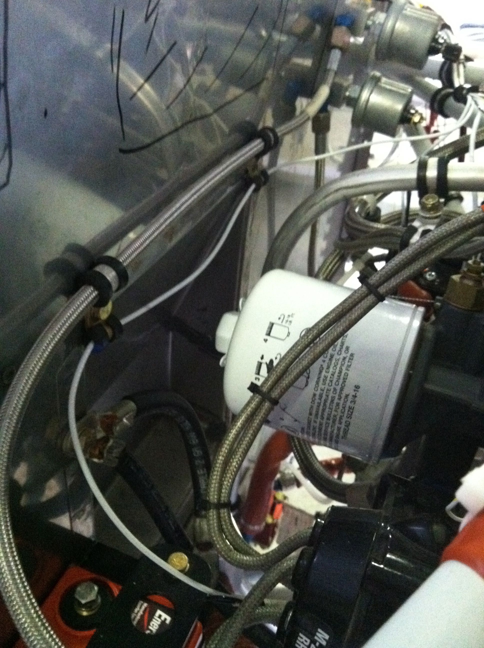
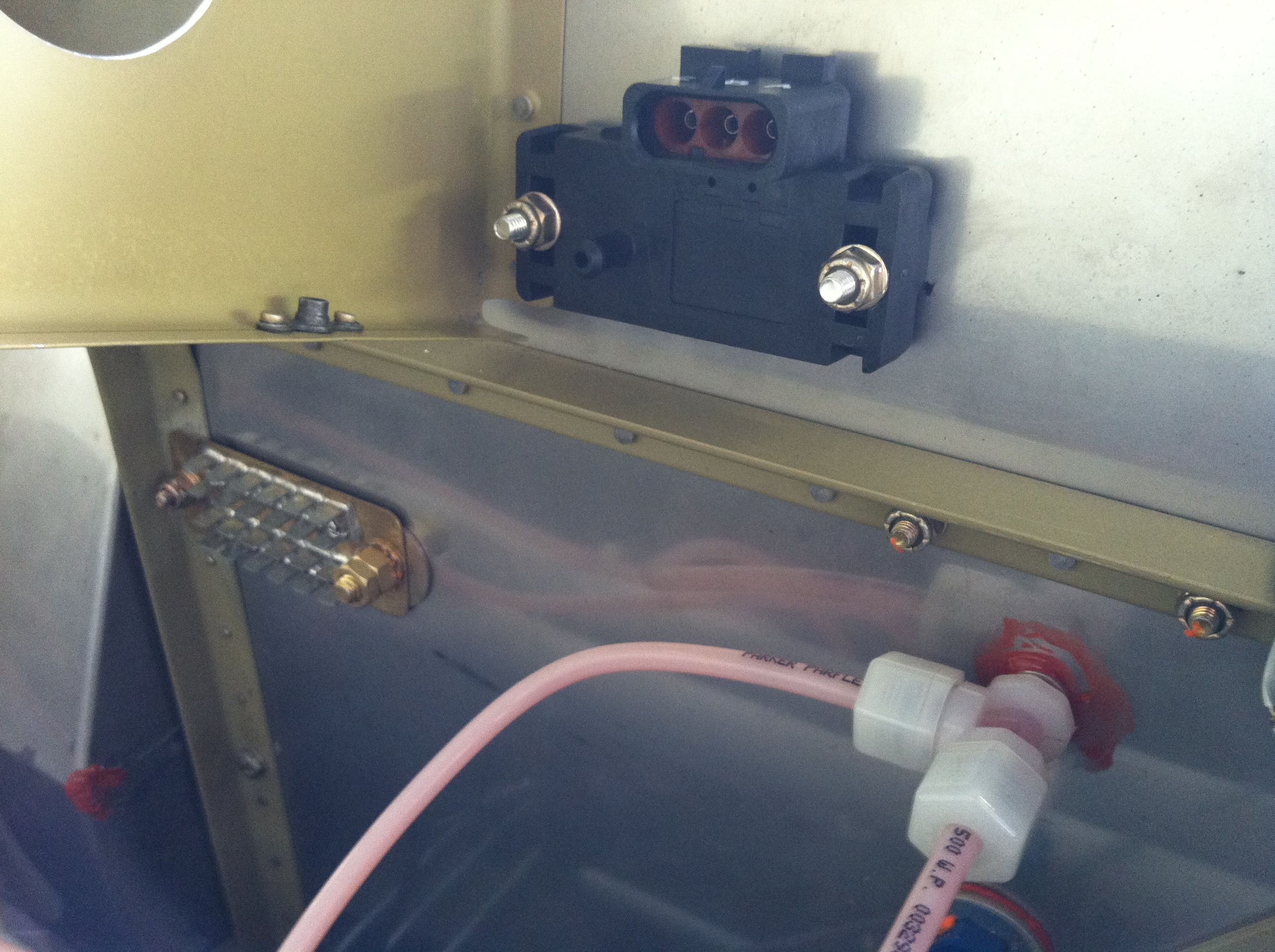
Worked on installing the Red Cube fuel flow transducer |
|
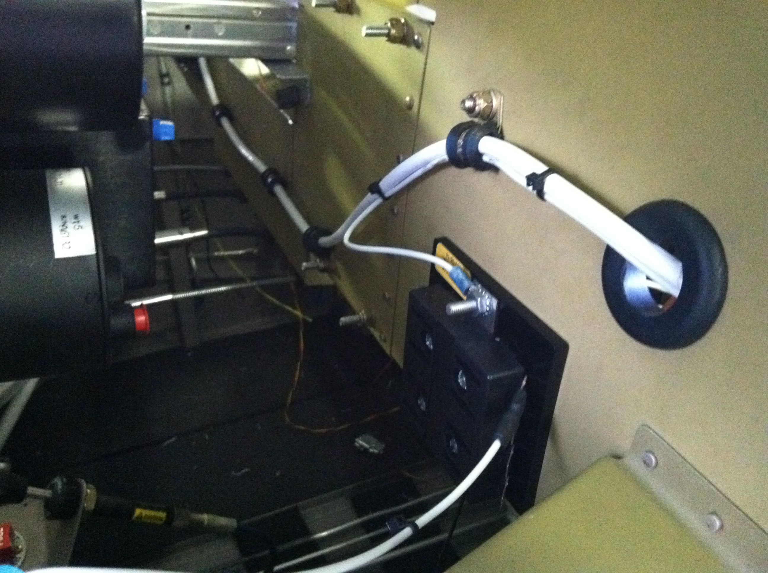
I haven't log time here in a while, but I have been spending hours mulling over the firewall forward installations. Today I worked on getting the Red Cube fuel flow transducer installed. I decided to mount the red cube on the left side of the firewall between the fuel pump and carb. The photo show a hefty 2.5 x 2 x 3/16" piece of angle - it's what I had on hand. The long "walrus tusk" bolts are just temporary while I wait for my shipment of parts. The angle mount bracket is attached to the firewall with two countersunk #10 screws through the firewall stiffener angle. I will put some lightening holes in the angle, or may replace it with some 1/8" angle that I have on order. This placement will require either a 45 or 90 AN fitting entering the red cube and a 45 degree fitting exiting the red cube. Also, the flow is just below the carb so I am adhering to the directions by not having the flow go down out of the red cube. I had first wanted to mount it above the gascolator but a few folks seemed unhappy with this. Inside the cockpit puts it on the wrong side of the of gascolator so I choose the location that some folks seem to think will work best for my set up. I am done with the fuel lines inside the cockpit, so I am not wanting to go back and redo a bunch of that to accomodate the red cube. Would have been nice to know that I would even have to install a fuel flow transducer a good while back, but that's kit building!
|
|
|
2010-03-18 |
Hours: 1 |
Category:
Firewall Forward
|
|
Manual Ref:
|
ID#:
1033
|
|
Painted the battery tray assembly |
|
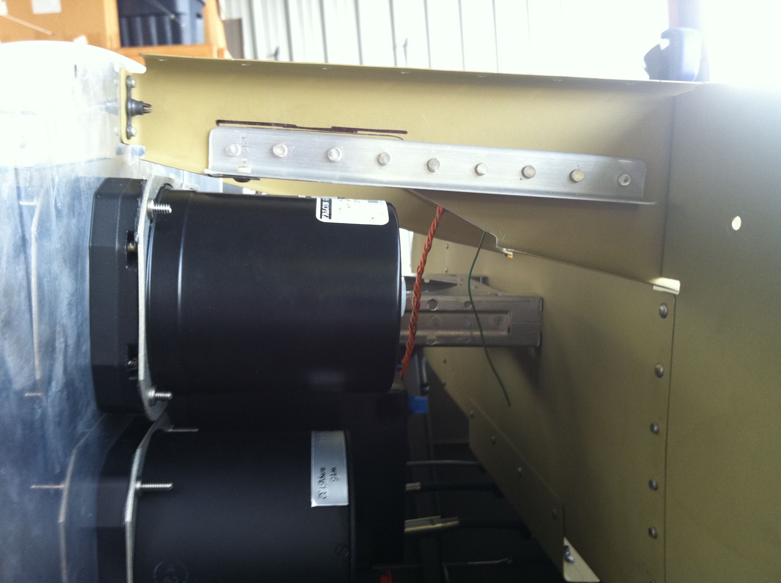
Painted the battery tray assembly and strap with some semi-gloss "Deluxe" black high heat paint. Probably overkill, but I needed some to touch up my BBQ grill at home.
|
|
|
2010-03-16 |
Hours: 2.5 |
Category:
Firewall Forward
|
|
Manual Ref:
|
ID#:
1032
|
|
More F-7127C retainer strap work |
|
Got the lightening holes drilled in the F-7127C retainer strap using a unibit. I had to buy a new one because my old one gave out at the 1/2" drill - dulled out I suppose. Not bad after seven years. I primed all of the battery tray components and plan to paint them with some high temp black paint.
|
|
|
2010-03-11 |
Hours: 3 |
Category:
Firewall Forward
|
|
Manual Ref:
|
ID#:
1031
|
|
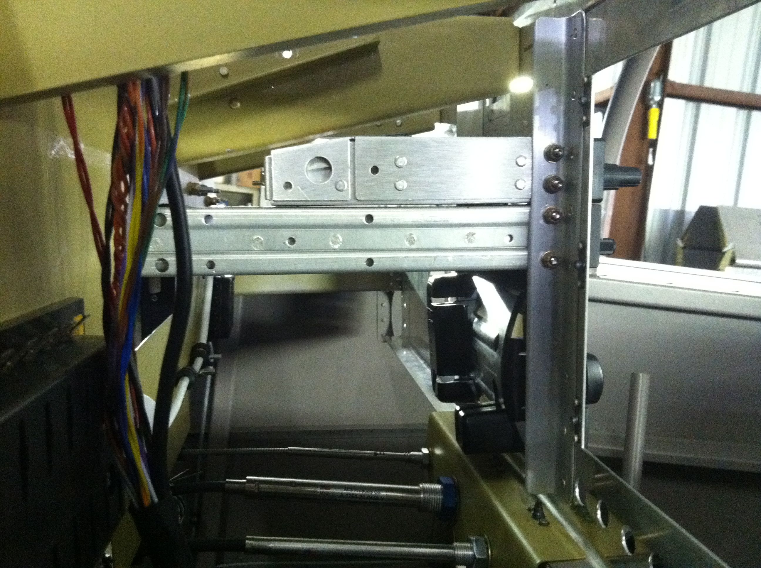
Finished battery box assembly, started F-7127C retainer strap |
|
I did not like the tight, forced fit of the three F-7127 battery tray assembly bolts to the firewall. It took way too much force to get the bolts in and tightened. I removed the battery tray from the firewall, removed the three nutplates from the F-7127A side angles so I could see how the bolt holes line up with the firewall. The two left ones line up perfectly as I would have guessed. The right hole did not line up. It was off by about 1/16". Warning: match drill this hole; don't just removed the rivet from the firewall and hope it lines up. I had to wallow out some of the firewall/stiffener to get the bolt to fit. Seems to be okay. Also started fabricating the F-7127C retainer strap. I marked the centerline, drilled one of the bolt holes, then match drilled the other to the battery tray assembly. I cut the strap to length - mine was not exactly to the measurements on the DWG 31A, so do not cut the bar to length first, get your bolt holes drilled as I mentioned above, then cut to length. I marked and drilled pilot holes for the lightening holes. I tried one with a 3/4" holes saw - it's a little wild. I will use a unibit for the remaining ones. I also cut the radius on the corners of the strap with a 1/2" radius, using a 1" dia. hole template.
|
|
|
2010-03-11 |
Hours: 4 |
Category:
Firewall Forward
|
|
Manual Ref:
|
ID#:
1030
|
|
Worked on battery box assembly |
|
Drilled and clecoed the F-7127A's to the battery box. I used a strip of .020 under the left one per plans as a shem to simulate the F-601K-1 firewall recess flange. Deburred everything, dimpled the battery box rivet holes, countersunk the F-7127A's and primed the exposed steel on everything. I had installed the nutplates but had to remove three of them while riveting the F-7127A's to the battery box because they were in the way. So, rivet the nutplates on last. I bolted the battery box assembly to the firewall. It was tough to get the bolts started as they do not line up perfectly with the holes in the firewall. It might have been better to match drill through the nutplates into the firewall, but I had earlier drilled out the rivets in the firewall and enlarged the holes to #12 for the AN3 bolts.
|
|
|
2010-03-03 |
Hours: 1 |
Category:
Firewall Forward
|
|
Manual Ref:
|
ID#:
1029
|
|
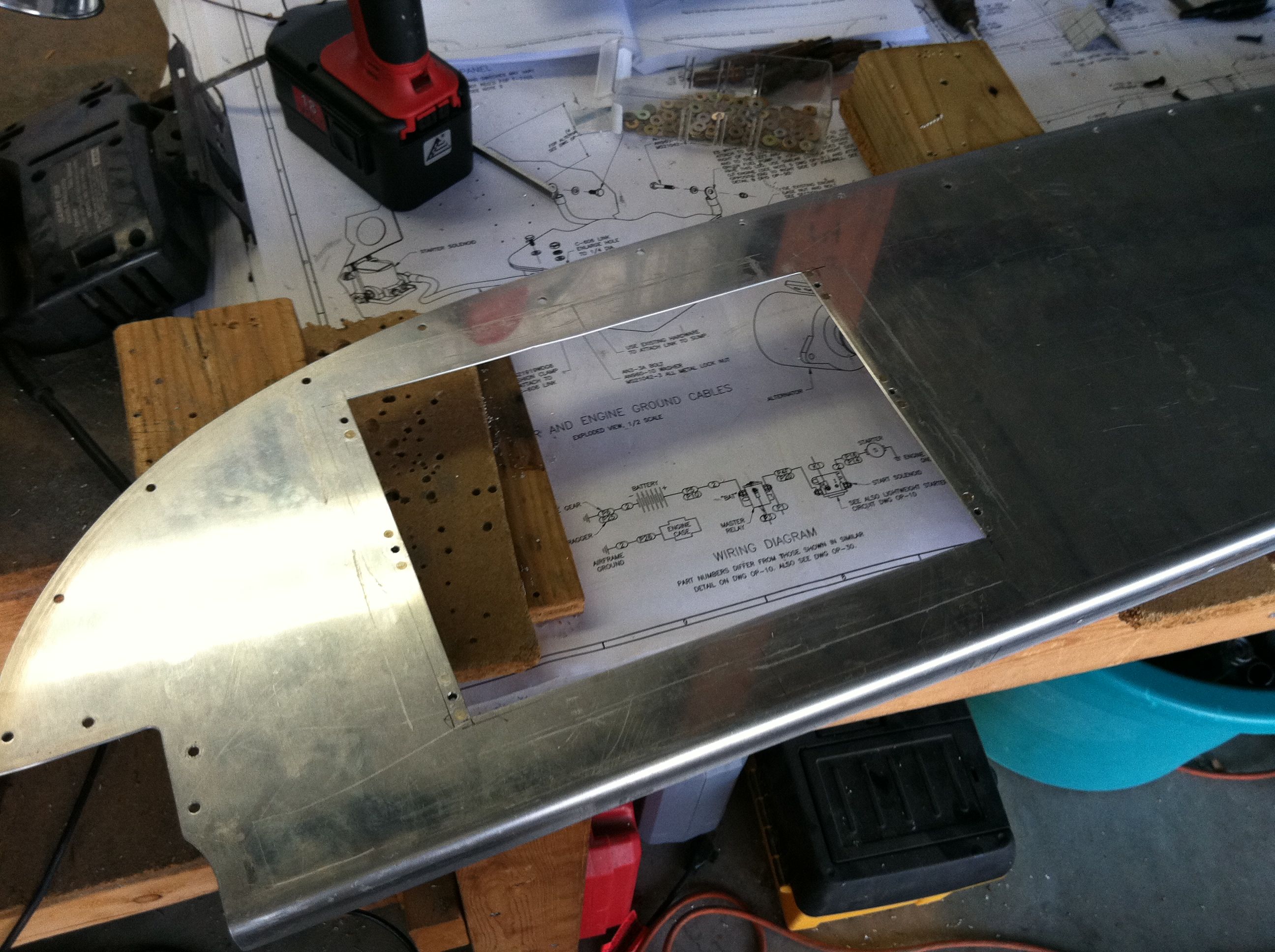
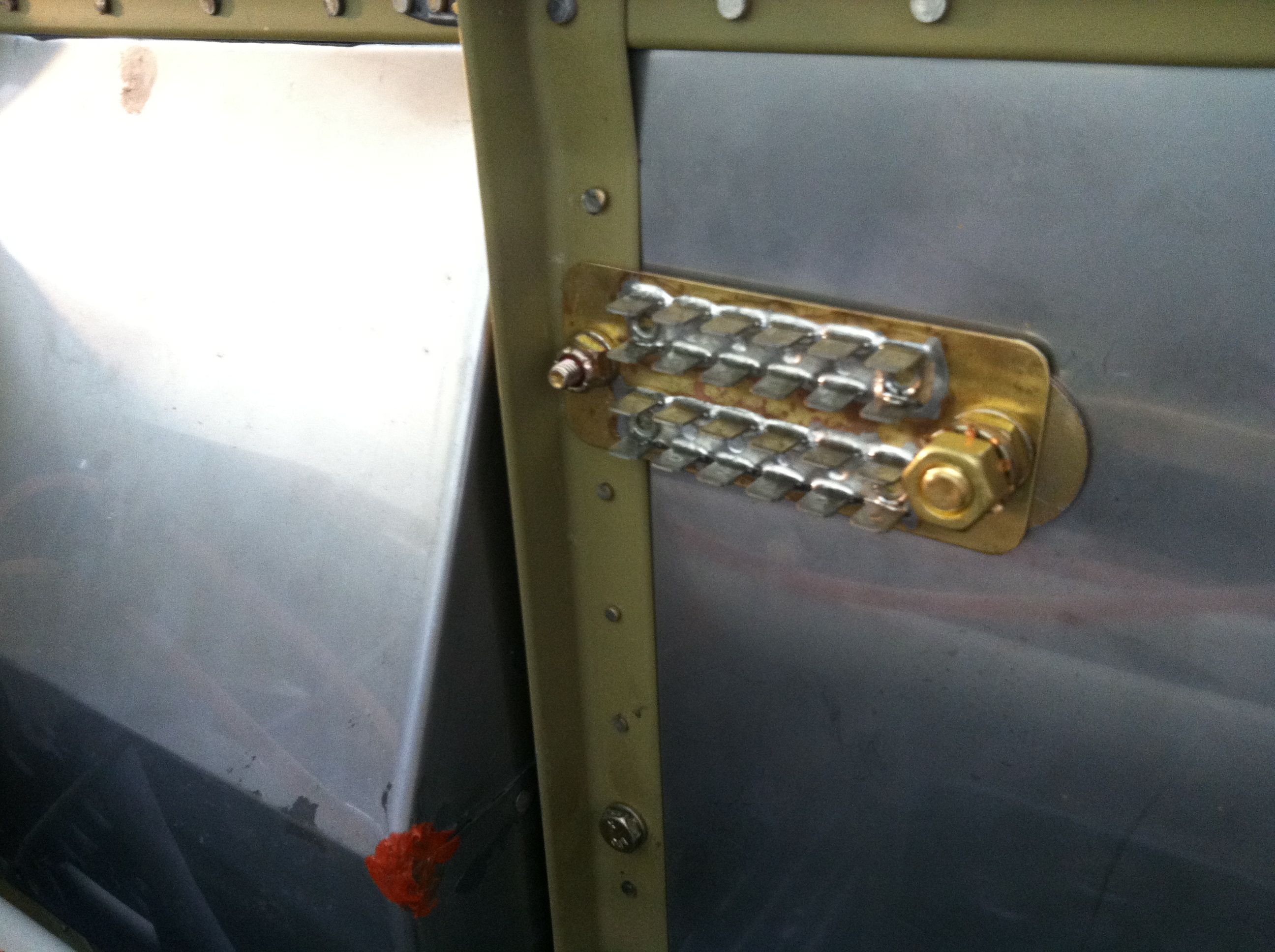
Installed master and starter relays and copper bar |
|
I installed the master and starter relays, bolting them to the firewall. Then I cut to length and drilled the holes in the copper bar strips. After trying to fit the copper bar strips, I had to remove some flange material per the drawing from the lower left flange of the master relay. Then I reinstalled, tightened the copper strips on both the relays, then tightened the bolts on both relays to the firewall. I measured the centerline distance between both relay bolts to make sure of the length I needed to cut the copper strips. It is not exactly like on the drawing, so measure your actual situation before cutting and drilling the 5/16" holes. Drilling the holes was easy with the thinner unibit on my drill press.
|
|
|
2009-10-27 |
Hours: 0 |
Category:
Firewall Forward
|
|
Manual Ref:
|
ID#:
1027
|
|
So I leave Pam and baby at the hospital Tuesday morning to run some errands and do some paper work at home when I get a phone call from Peggy at the FBO. She said, "You have a shipment. There is an 18-wheeler here with an engine." I said, "Stall them, I'll be there in 15 minutes." And so I was out the door, running with no sleep. The FedEx delivery truck was parked on Jim Hamilton Blvd out in front of the FBO and the driver was sitting in the back on top of the engine box. LYCOMING was very visible from a good distance away! He helped me get it in the back of my pickup. I drove thru the gate and headed for my hangar. Uhhh...how am I going to get this engine out of the truck? Lucky for me, Xen, Jack and Allen were there and helped me slide it down a makeshift ramp of two 2x4's. And there the engine box sat in my hangar, glowing white. There was the great temptation to open it up, but I knew I needed to get back to the hospital so I would wait until another day to come open the box and ogle at the Lycoming blue engine. It's been a great week so far!
|
|
|
2009-09-04 |
Hours: 1 |
Category:
Firewall Forward
|
|
Manual Ref:
|
ID#:
1018
|
|
Finishing up slider canopy work |
|
Countersunk the rivet holes where the C-666 aft skirts over lap the C-660 side skirts. Pondered over what else I need to do before I start disassembling everything to prep it for painting. Hopefully, I'll have some Jetflex here next week so I can get everything painted and reassembed.
|
|
|
2009-09-03 |
Hours: 0 |
Category:
Firewall Forward
|
|
Manual Ref:
|
ID#:
1017
|
|
My Sensenich FP prop arrived today. I think it may have survived its trip despite UPS delivery (Under Perpetual Stress, or United Parcel Service?) One end of the prop box was totally torn away and open. Yikes! I pulled the newspaper out of the end of the box and it looks like everything is intact. I will wait until I get it to the airport before opening the box to inspect the prop further.
|
|
|
|
|
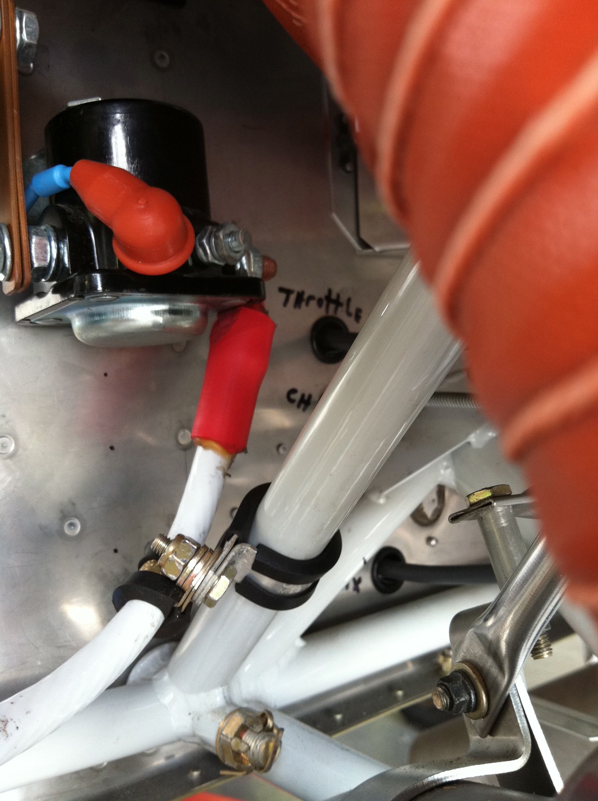
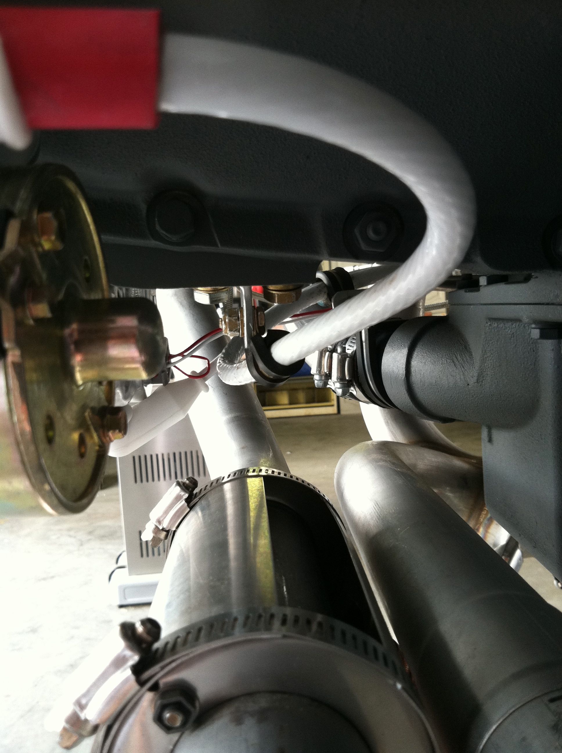
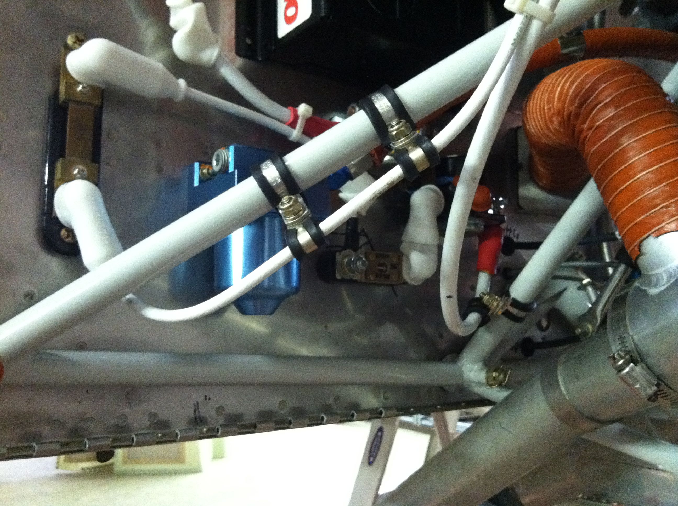
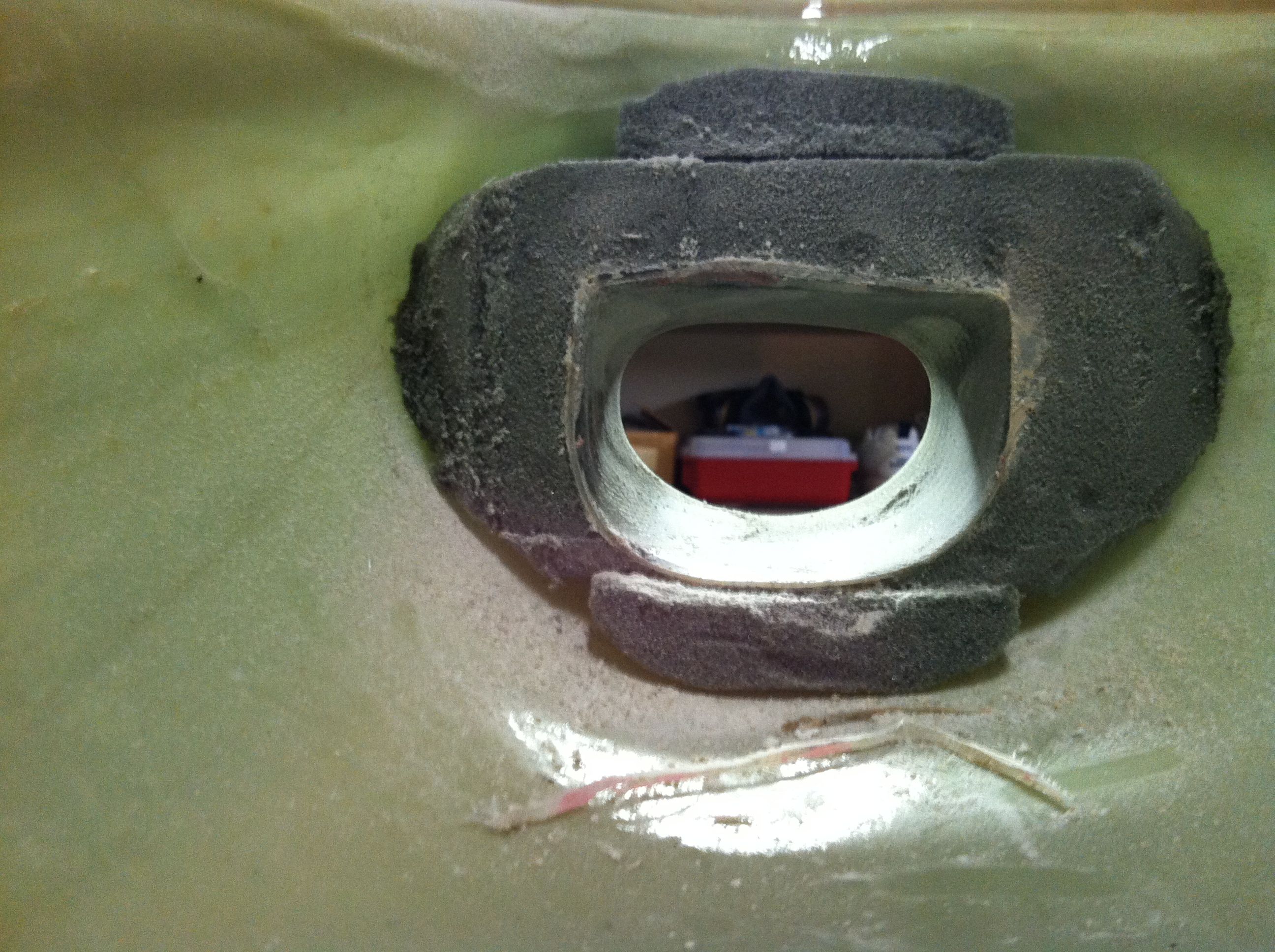
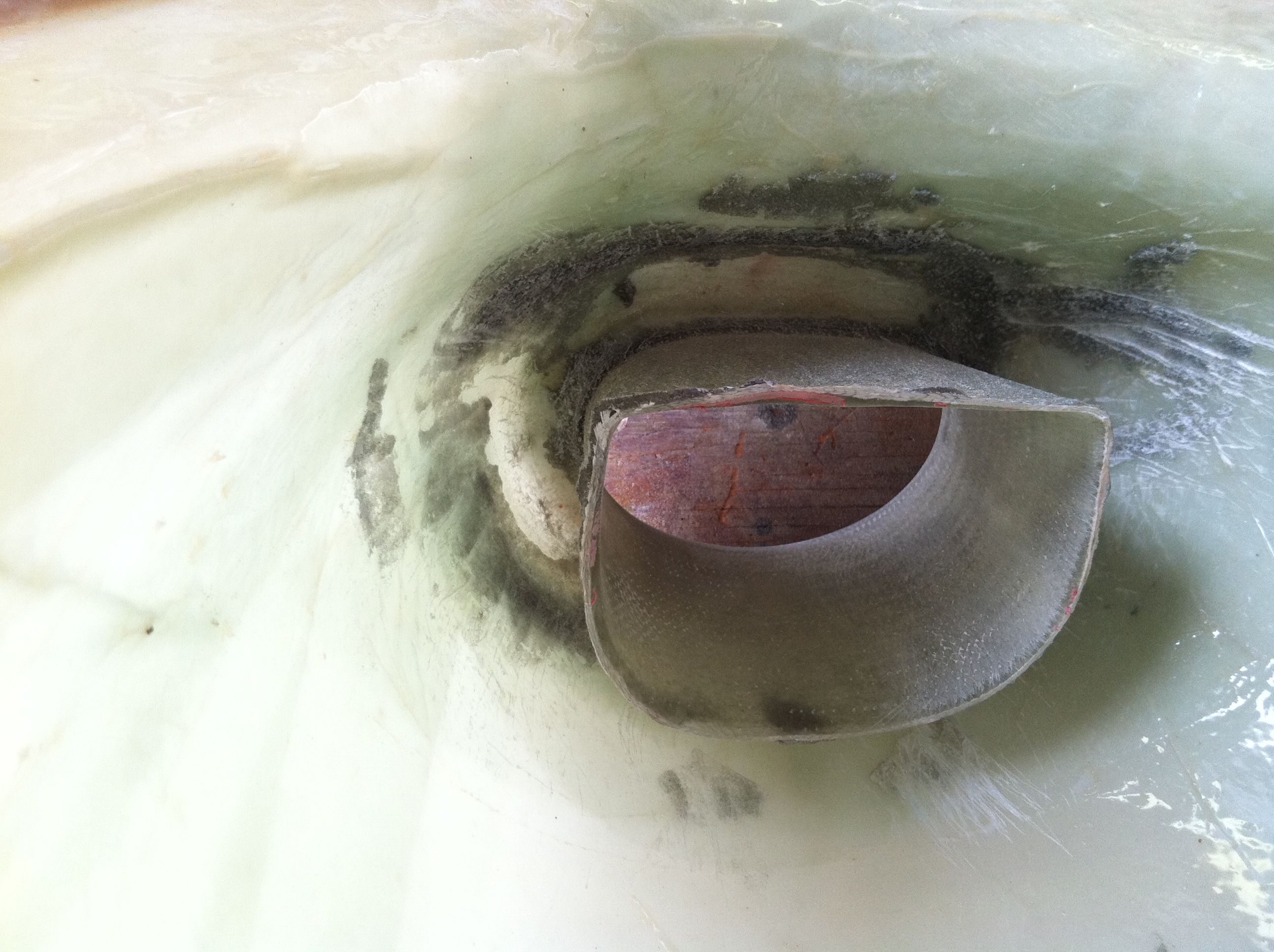
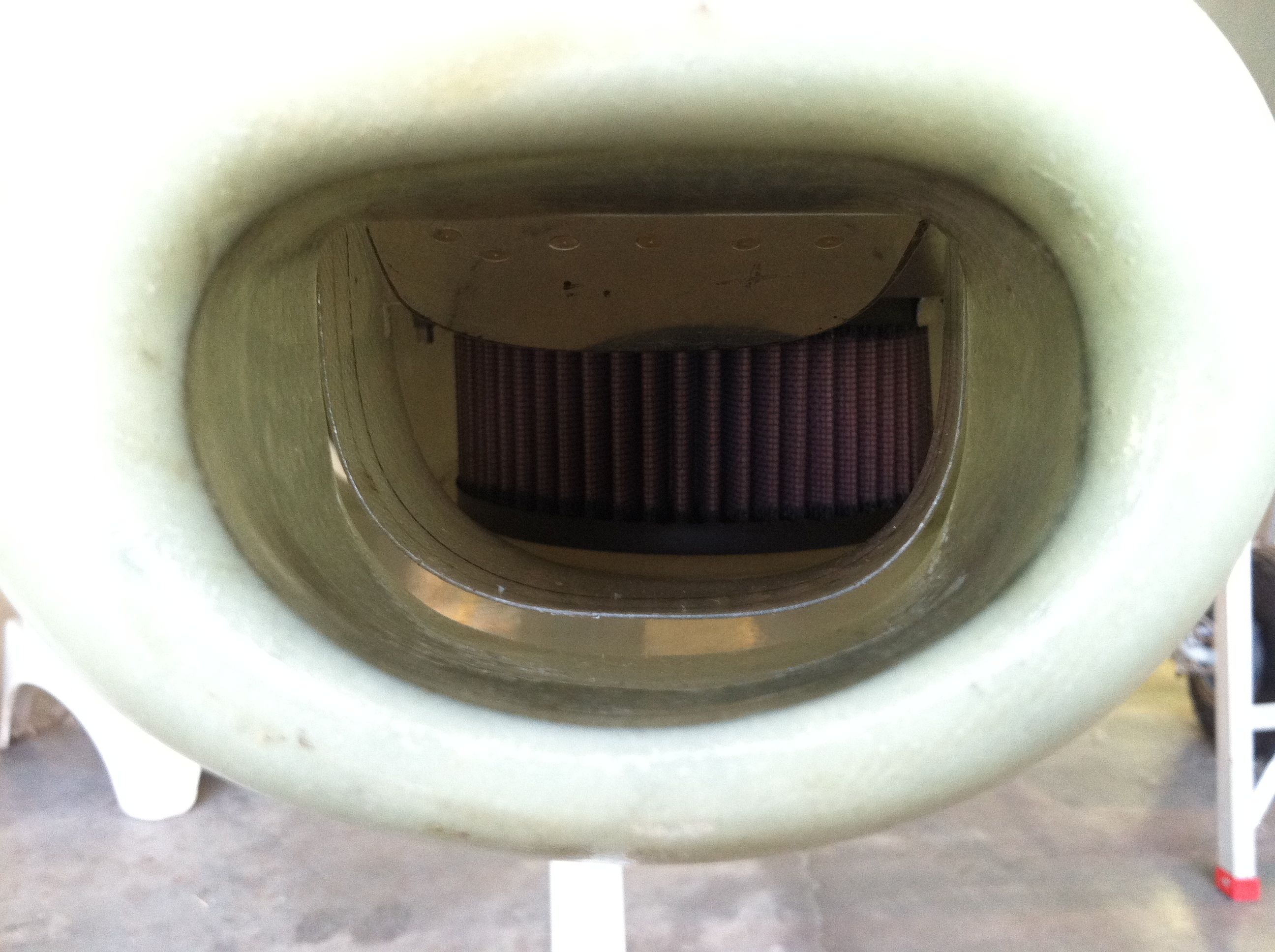
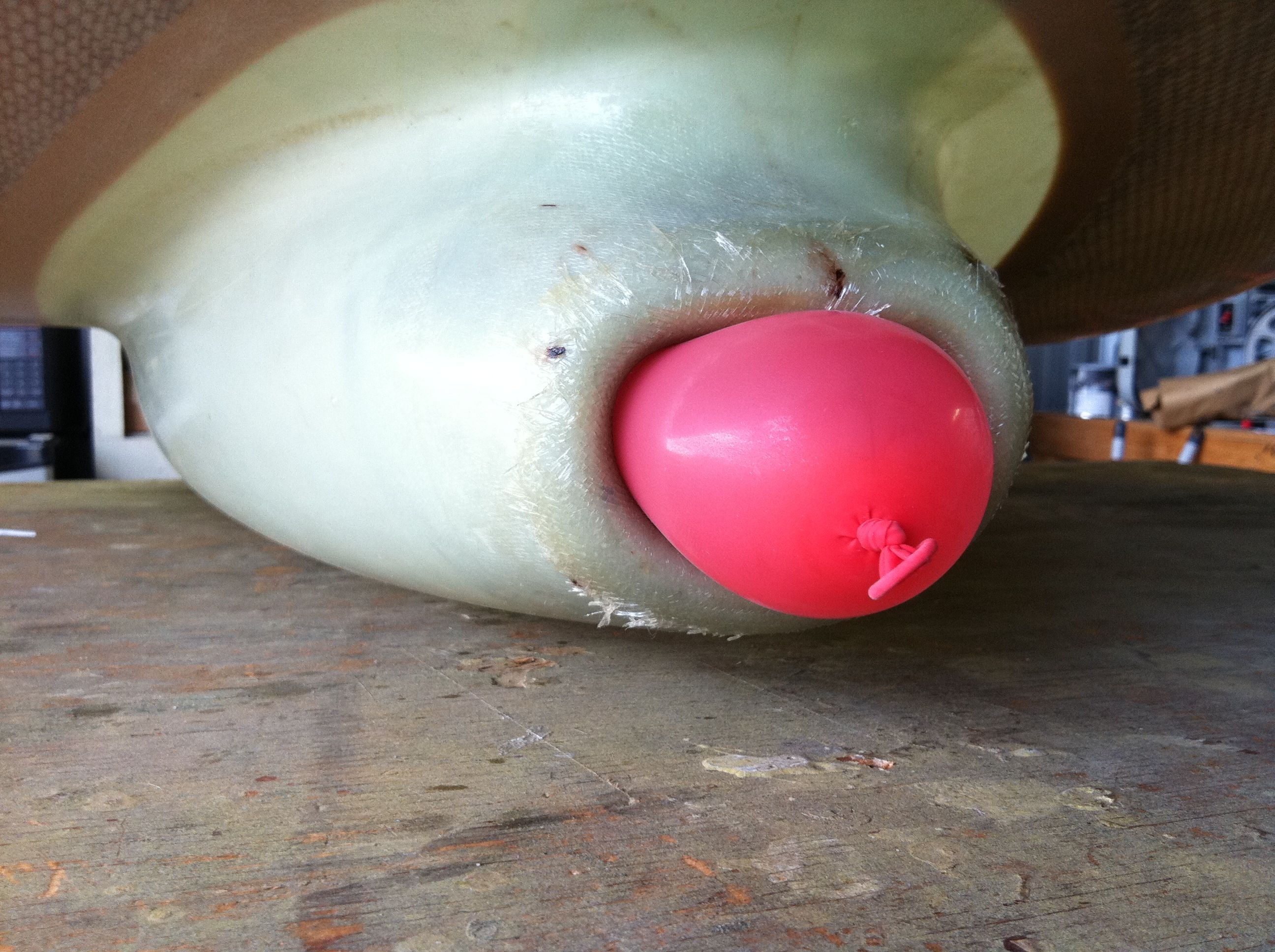
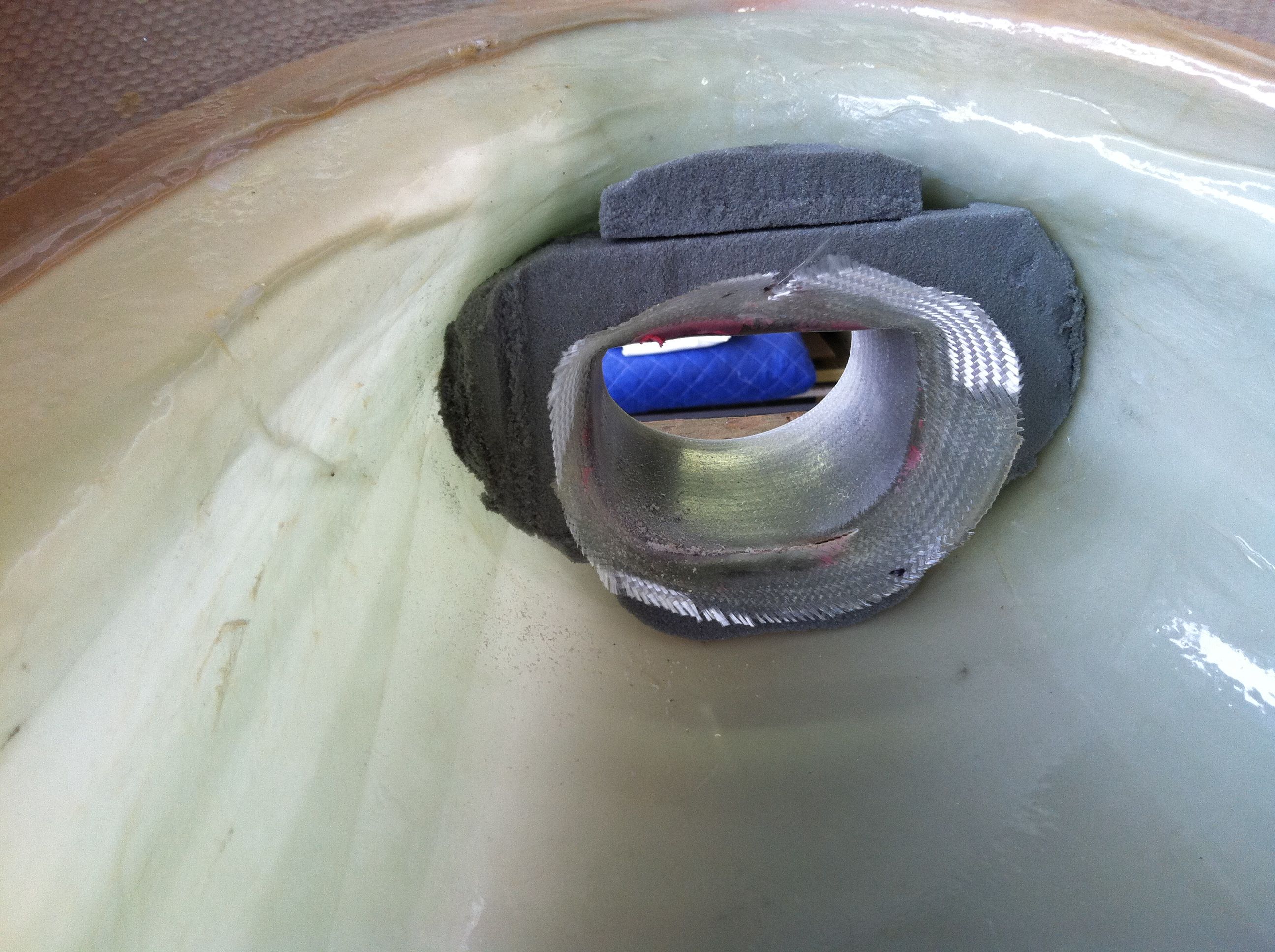
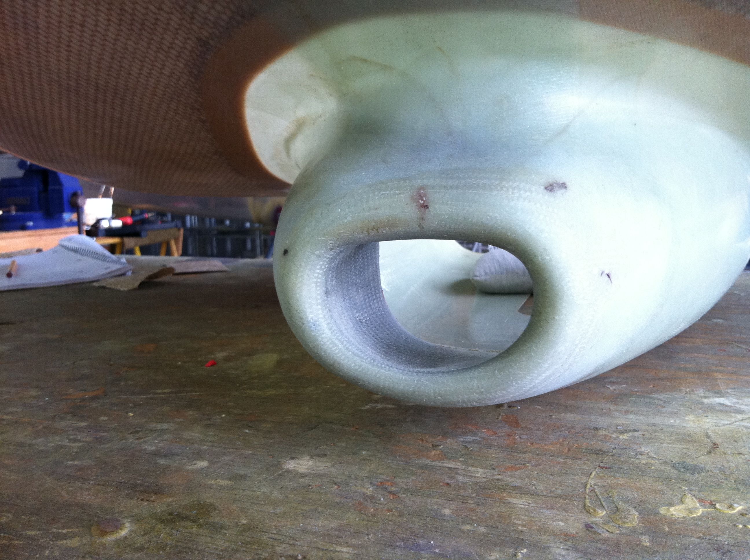
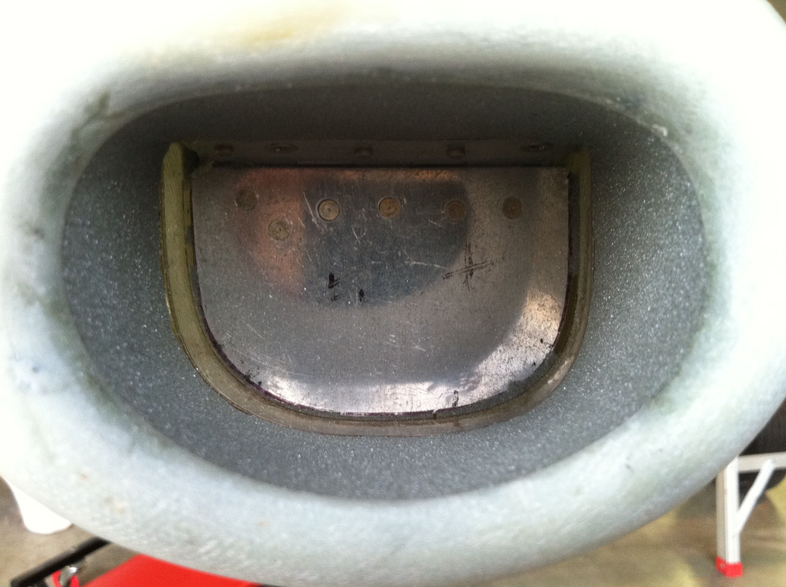
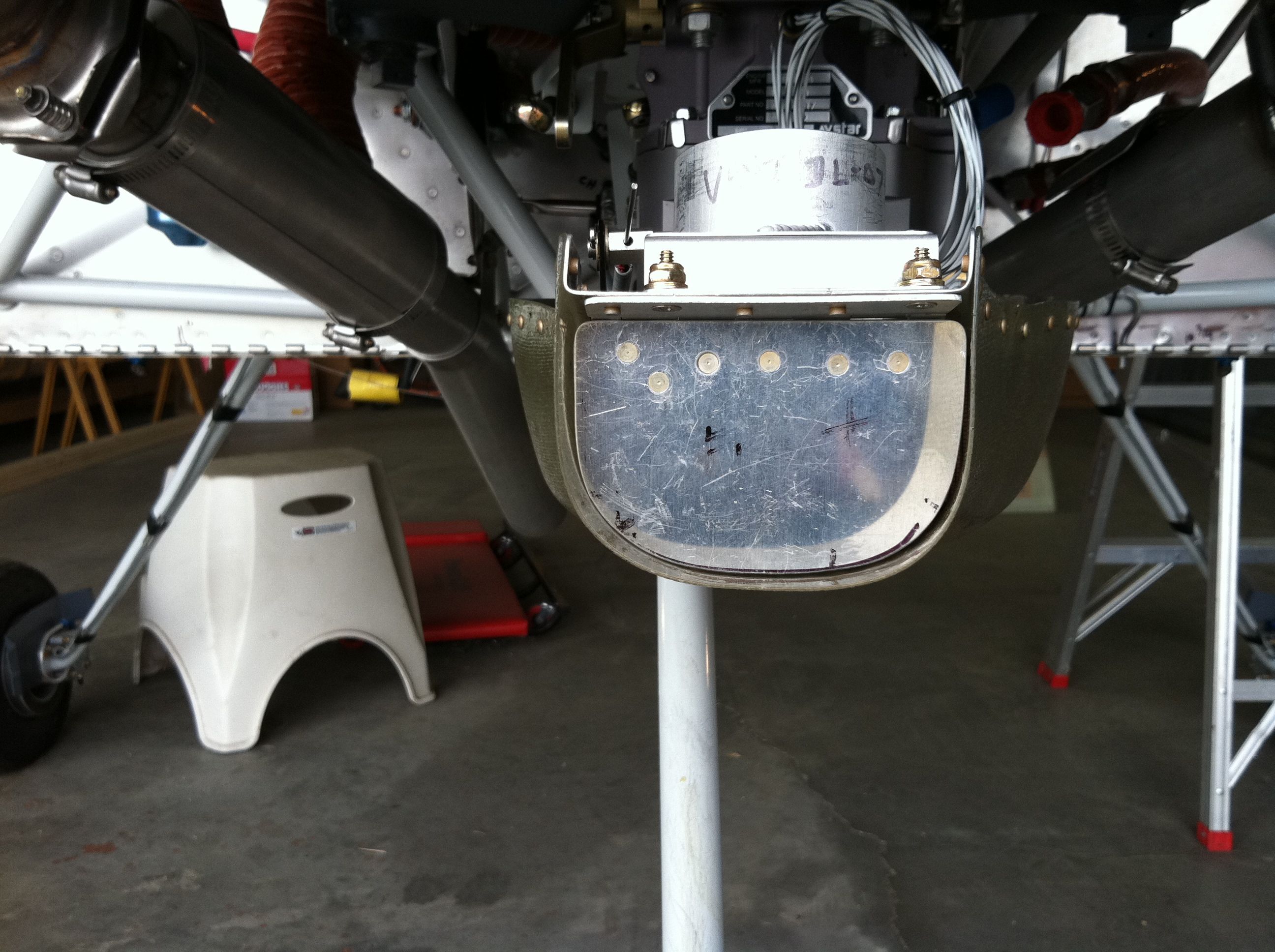
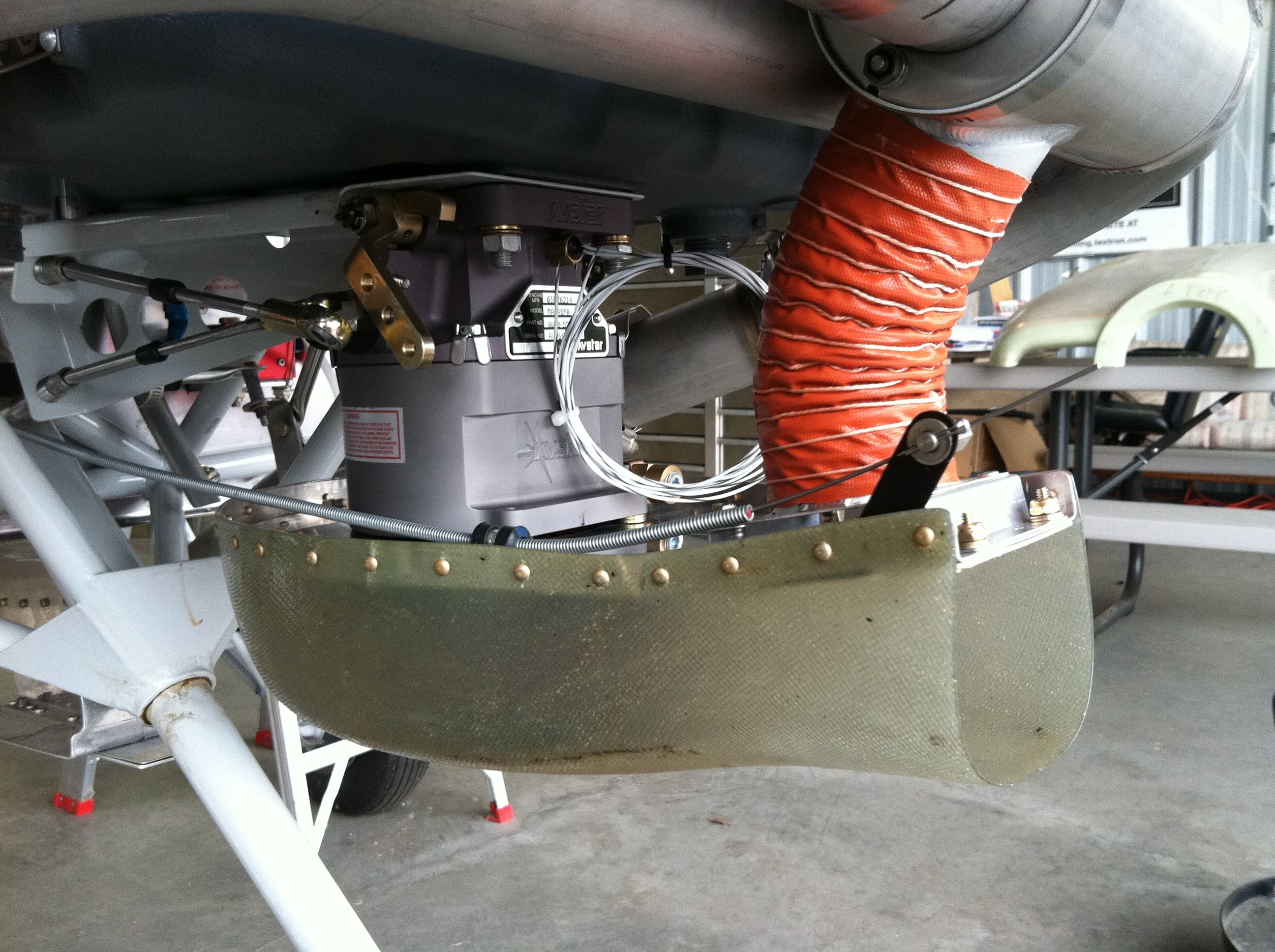
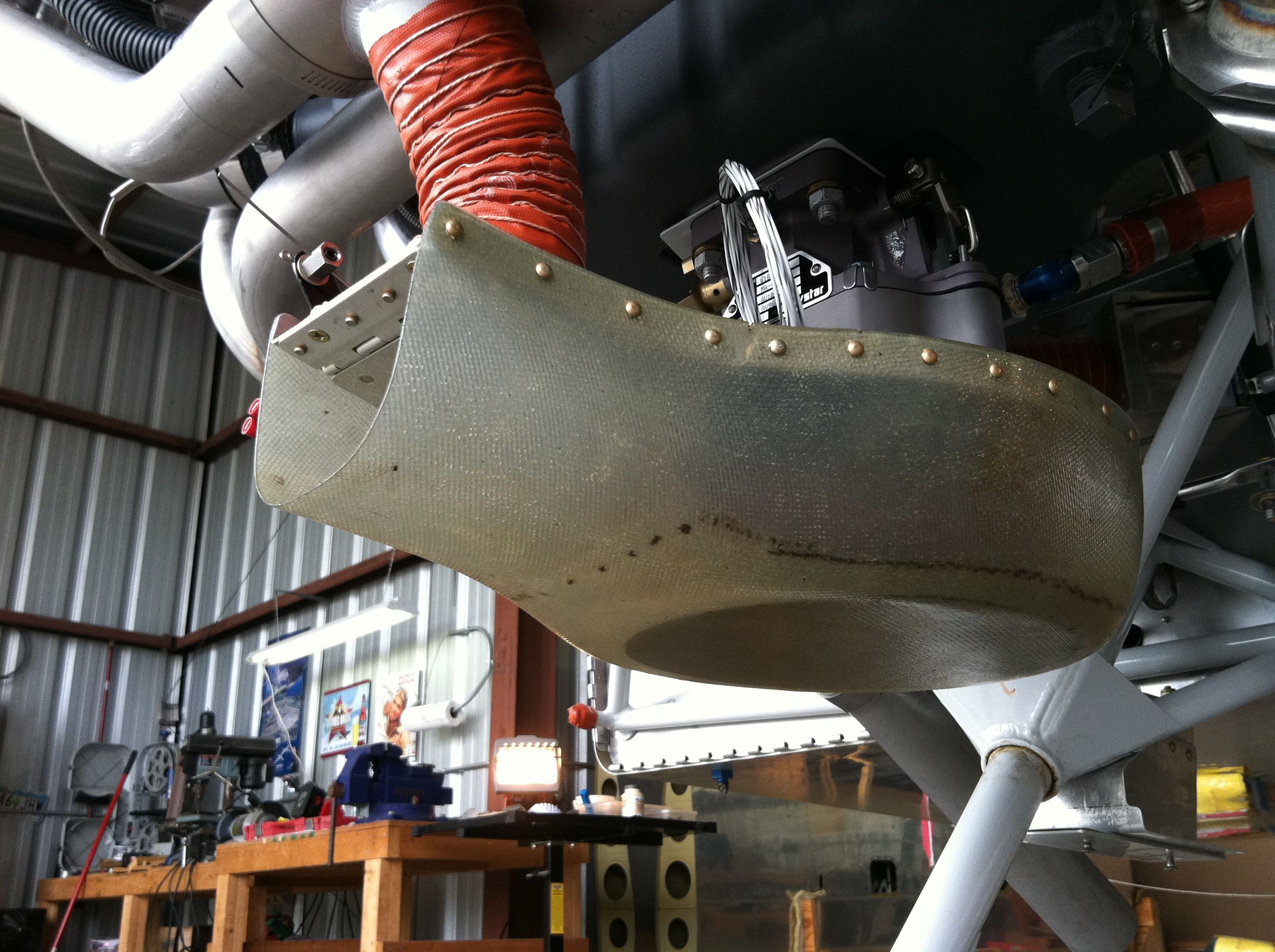
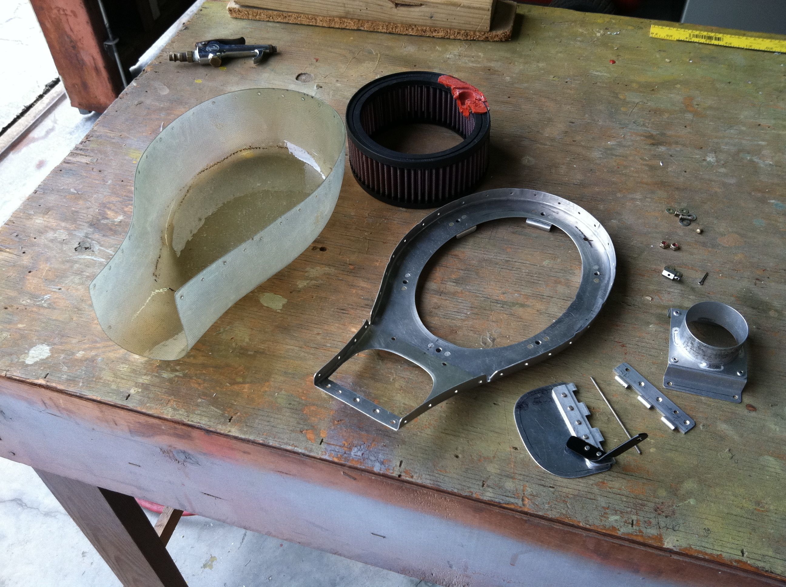
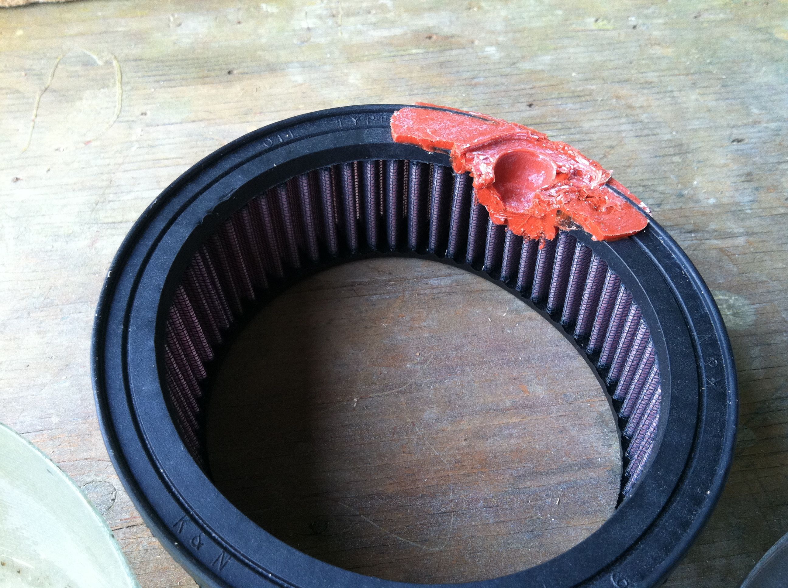
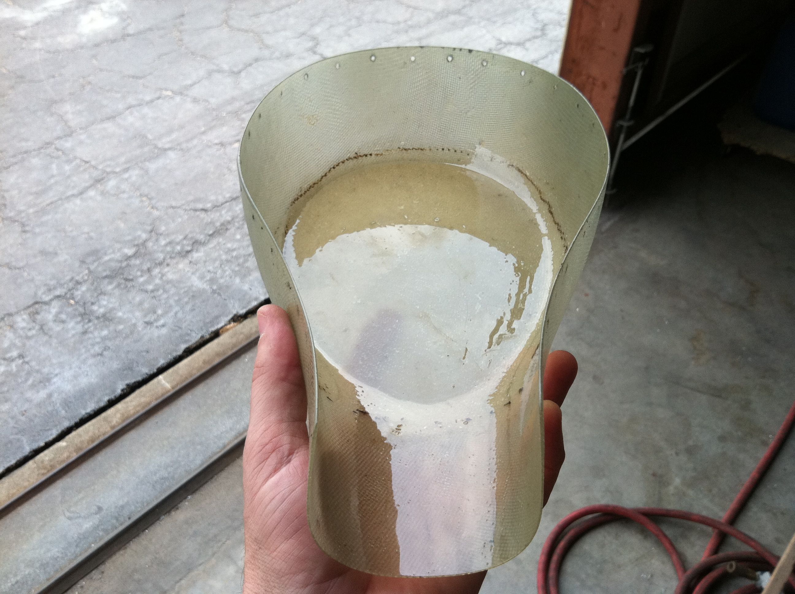
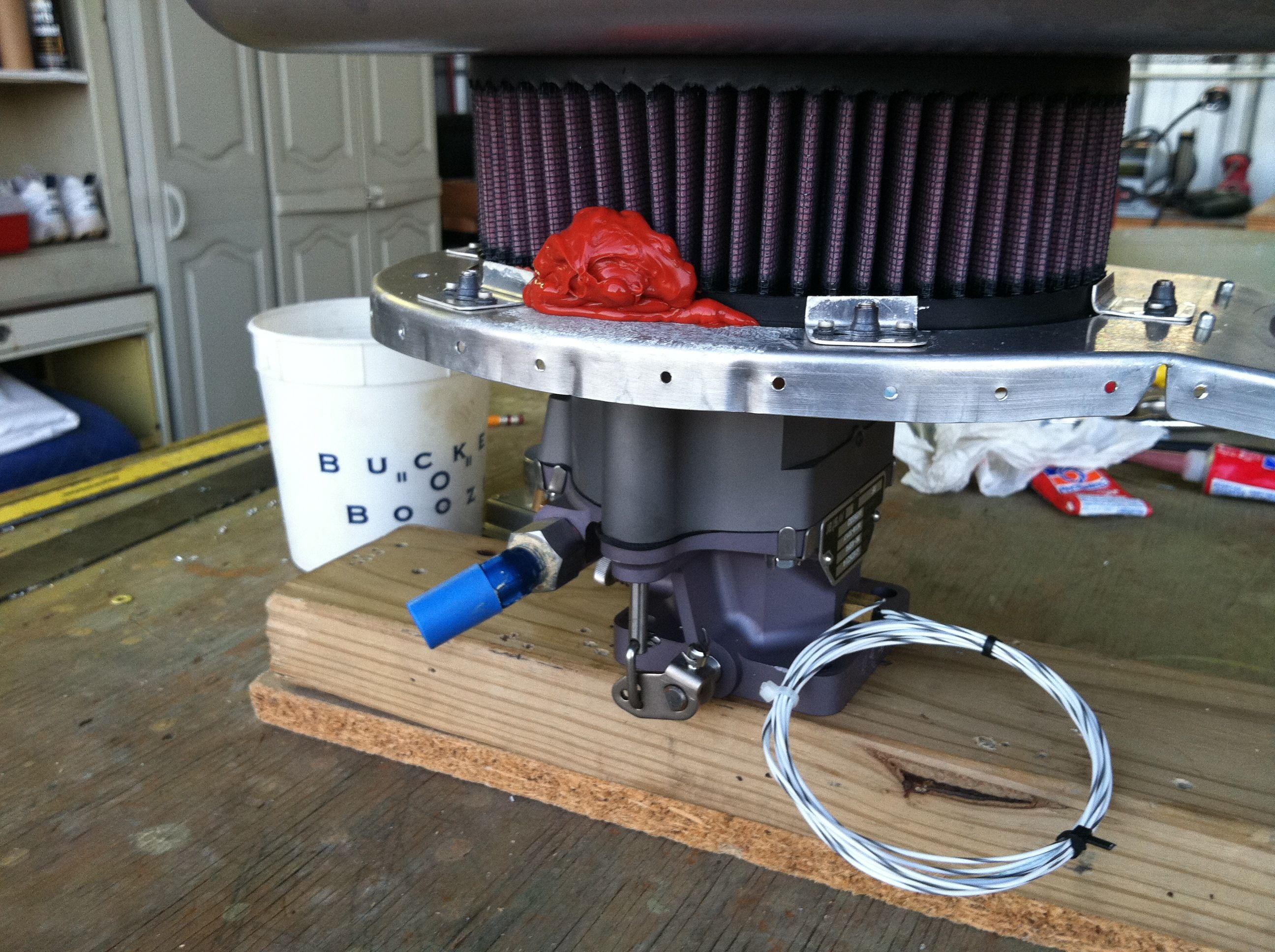
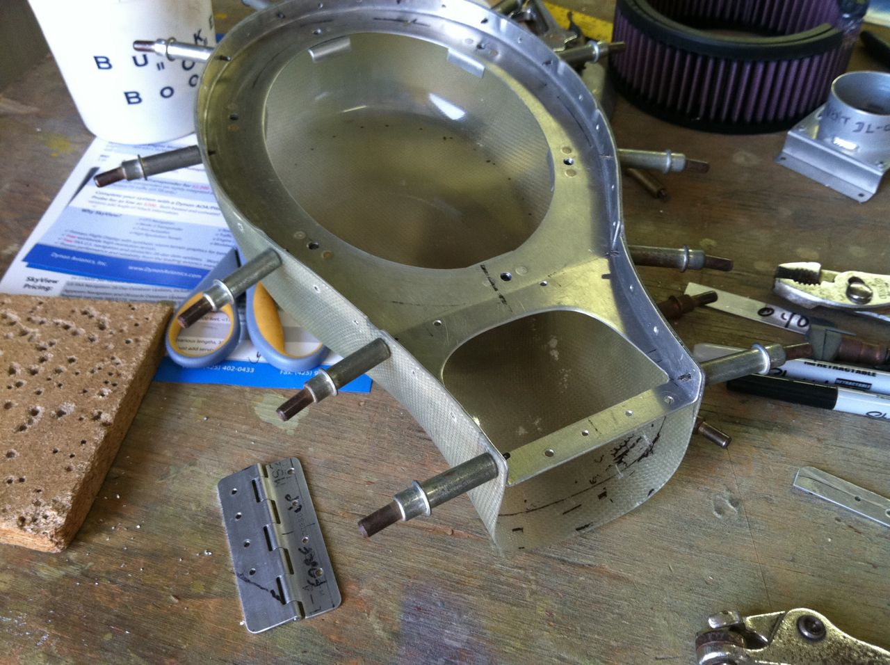
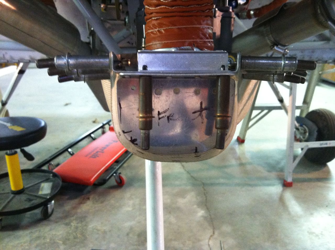
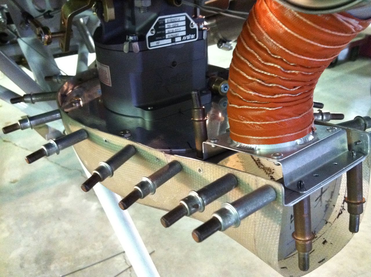
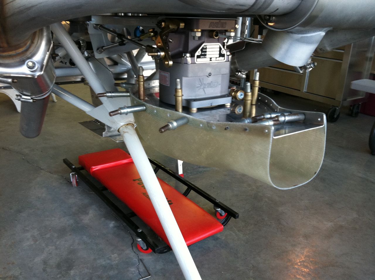
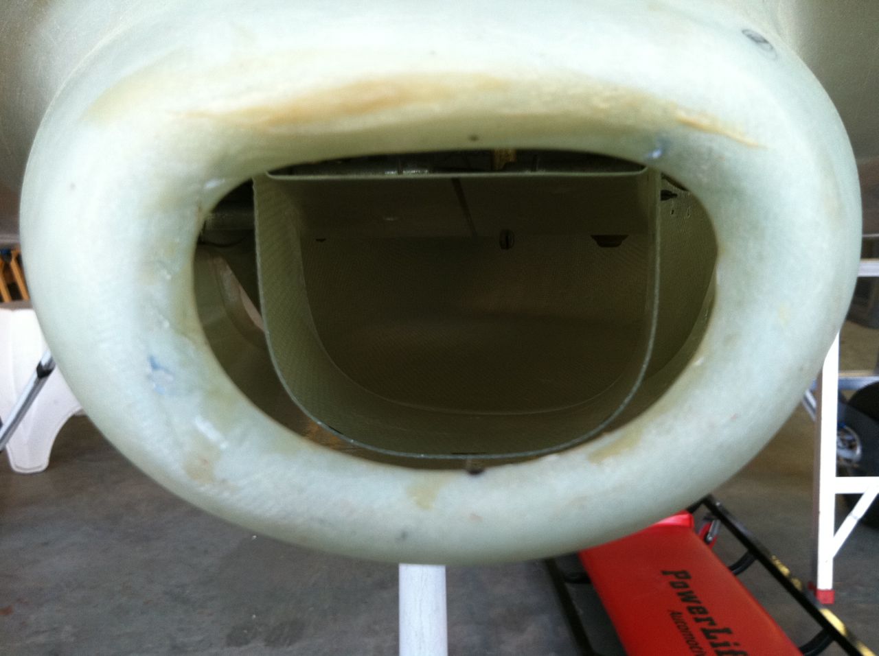
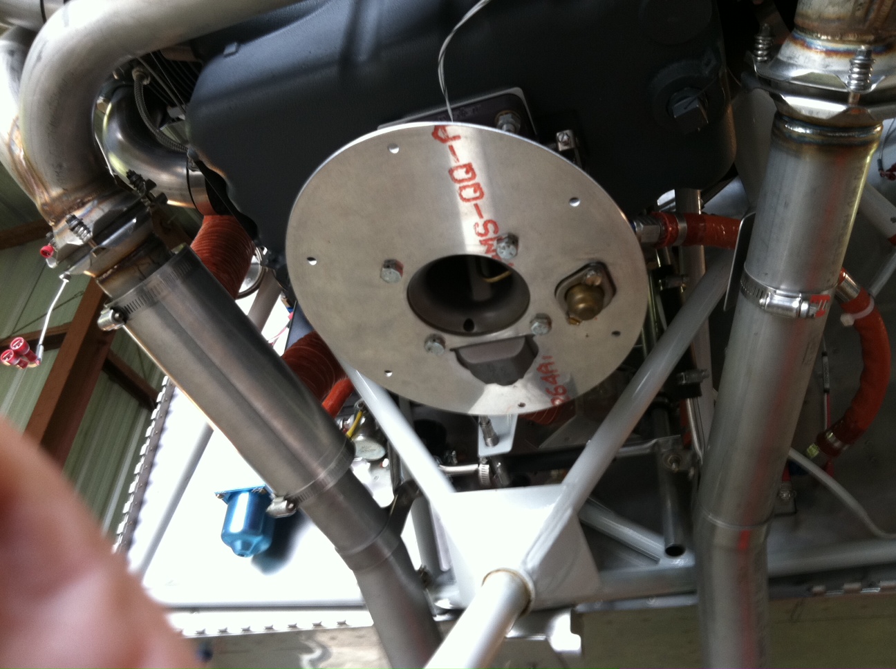
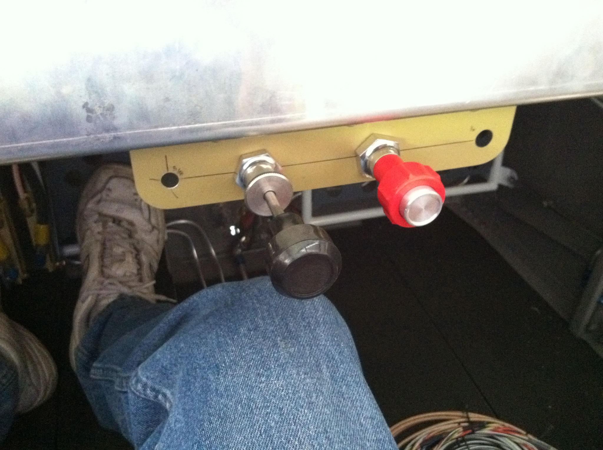
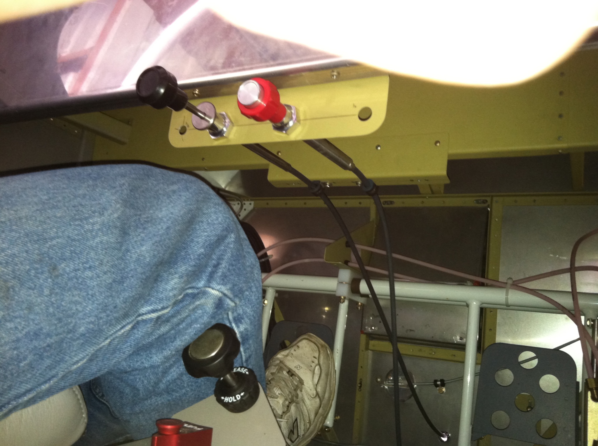
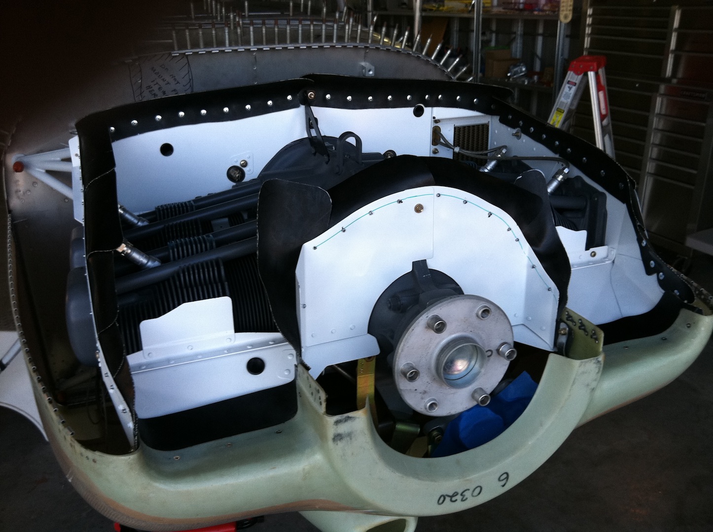
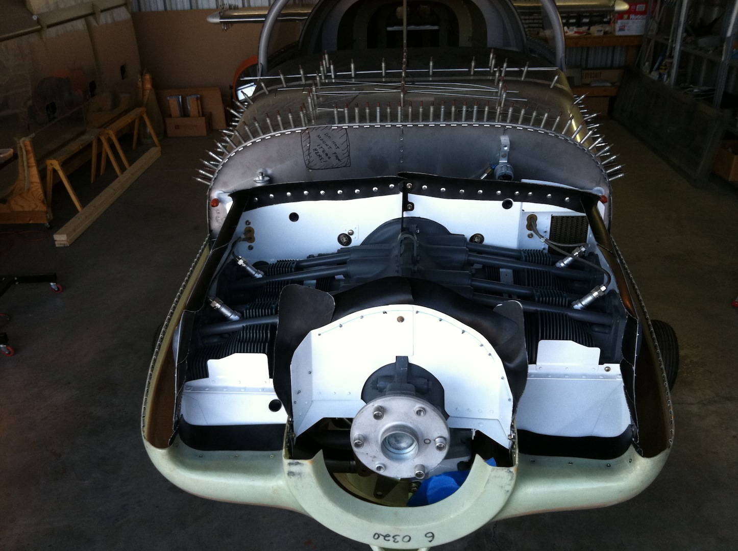
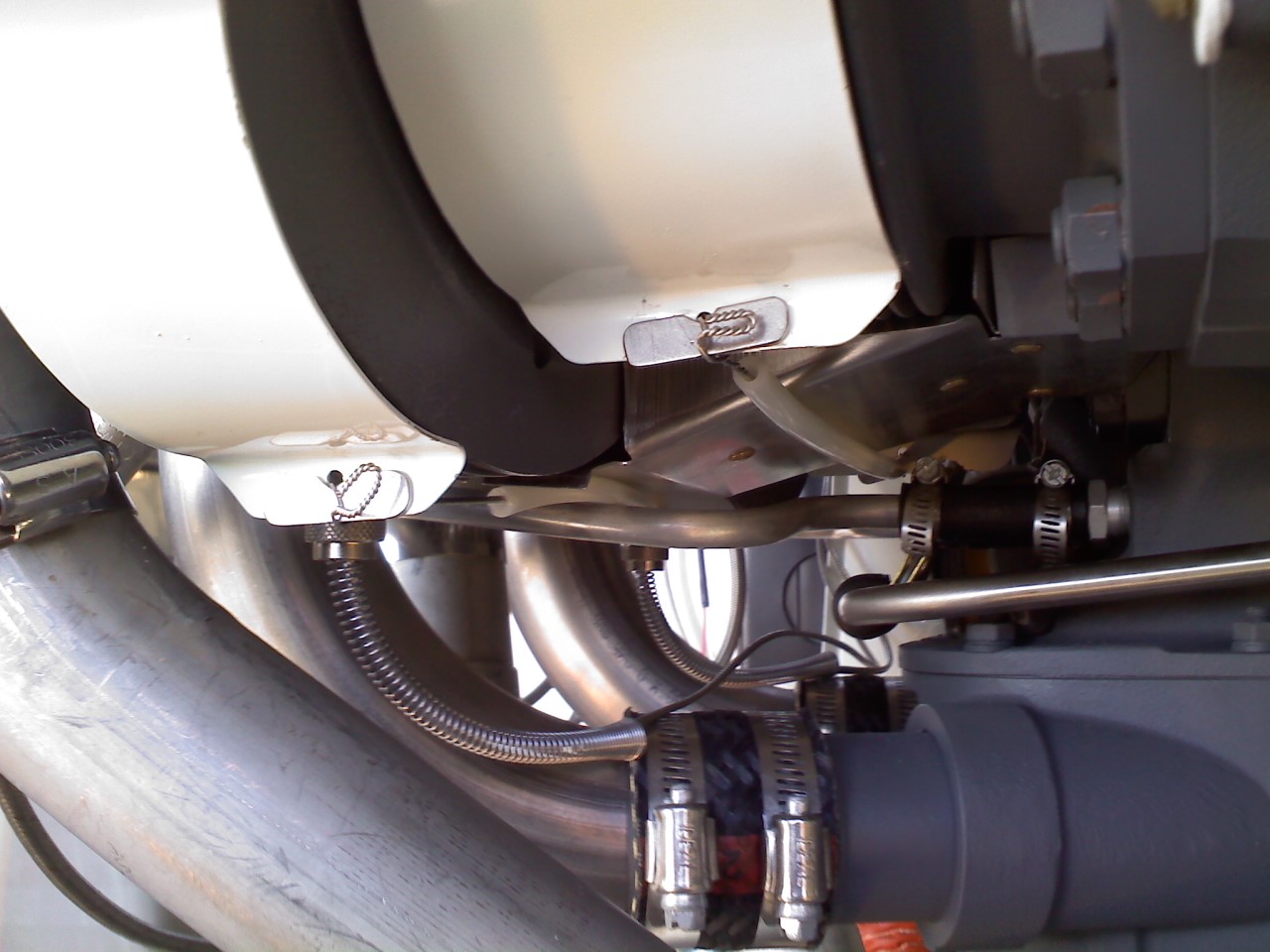
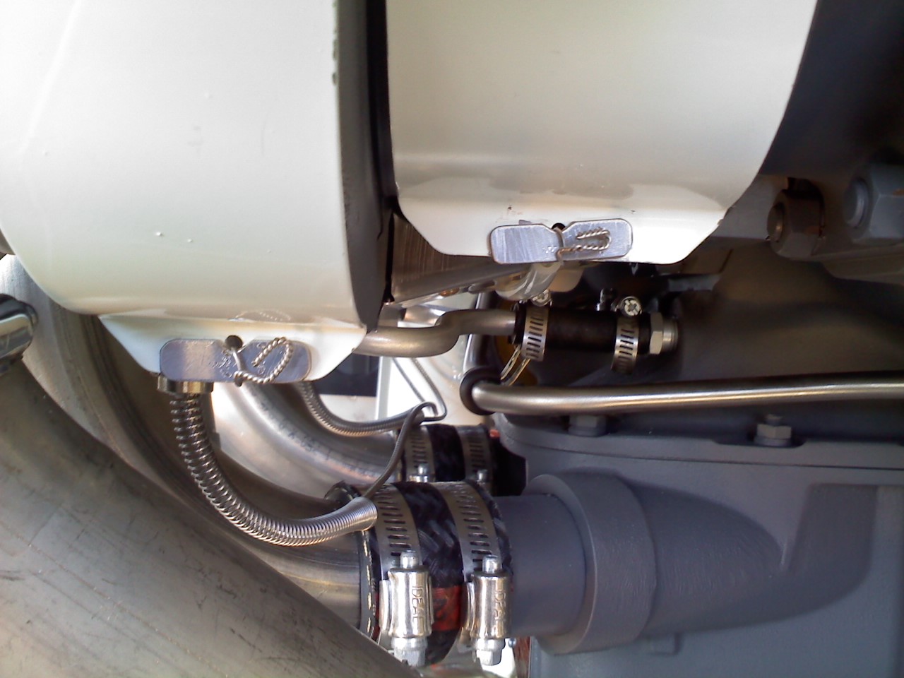
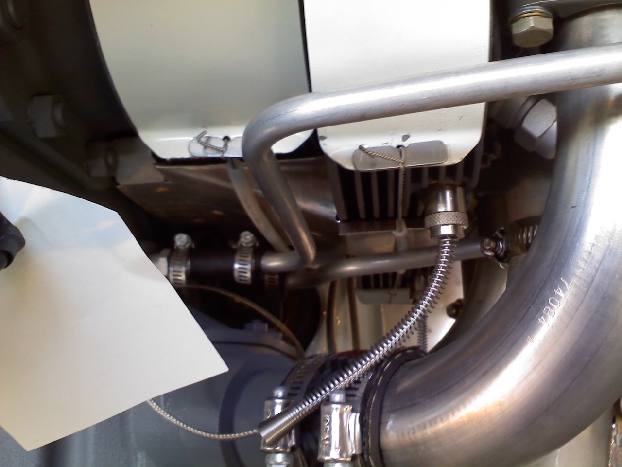
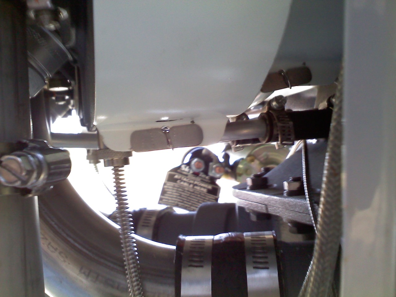
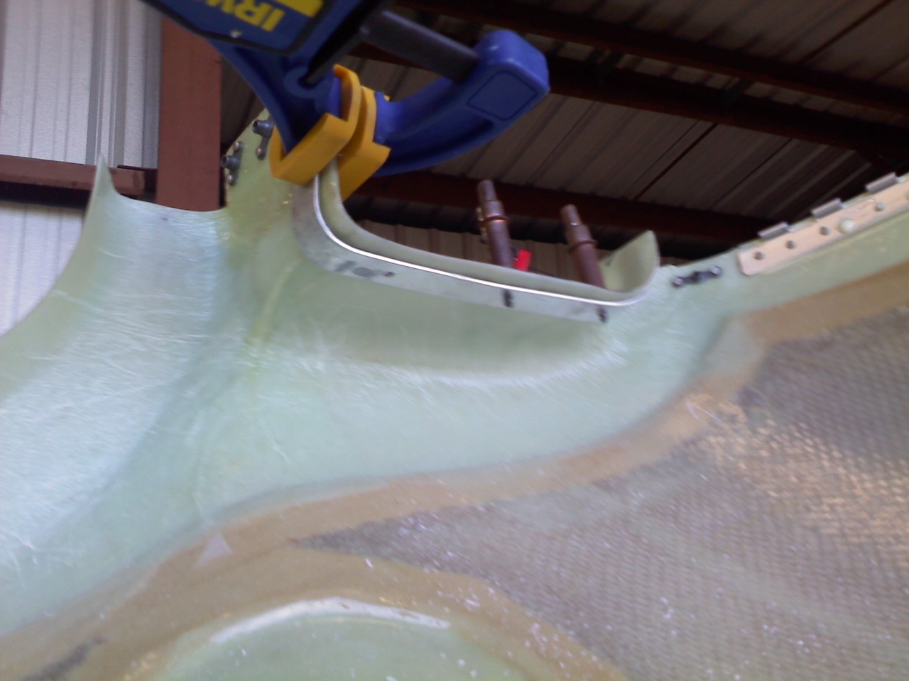
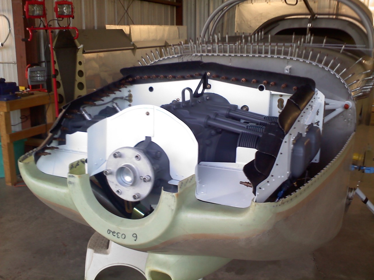
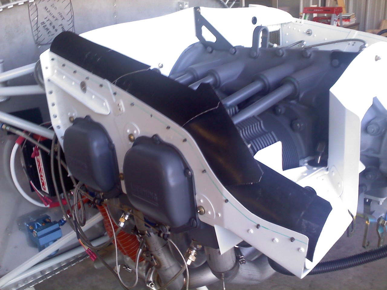
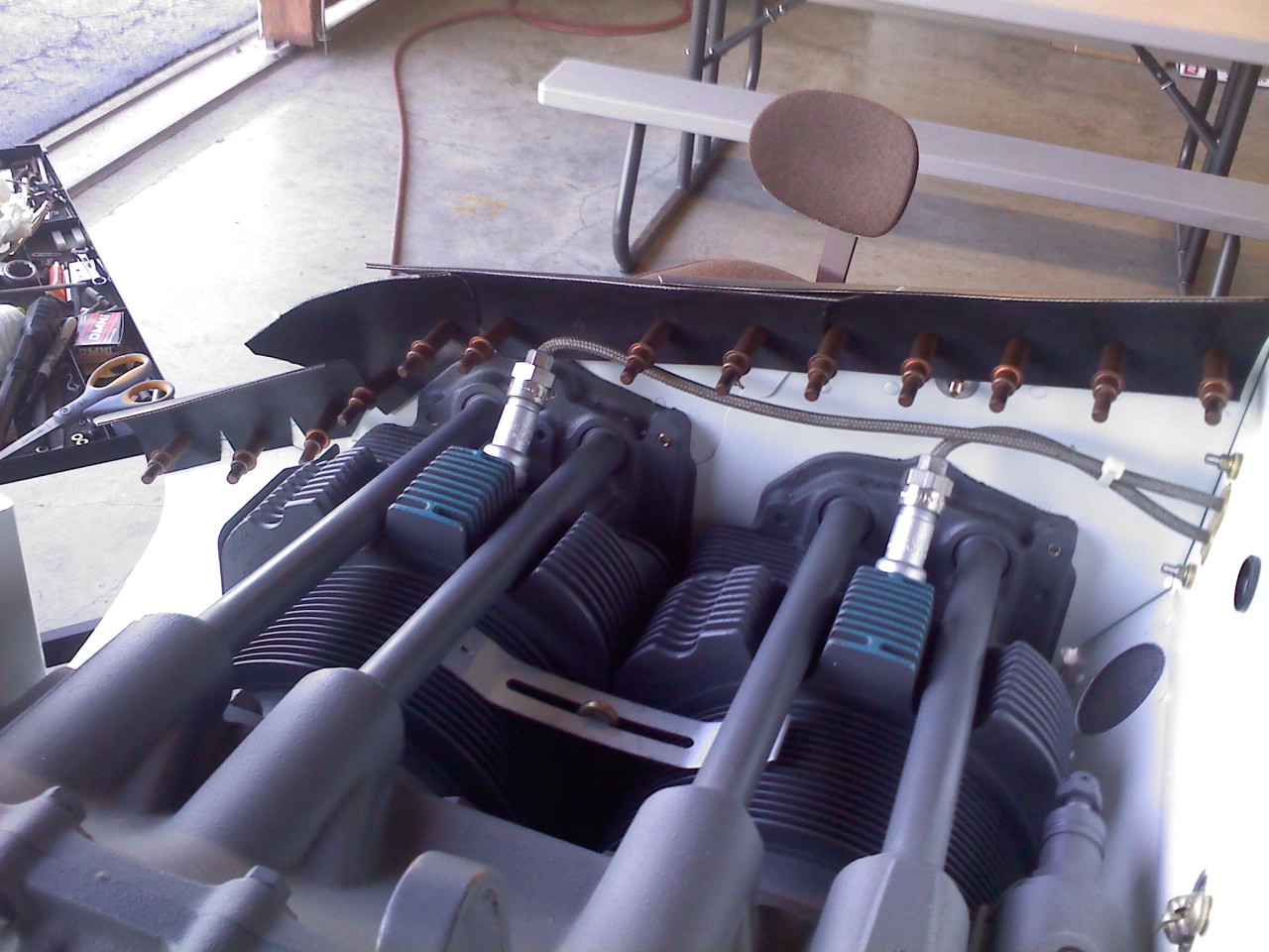
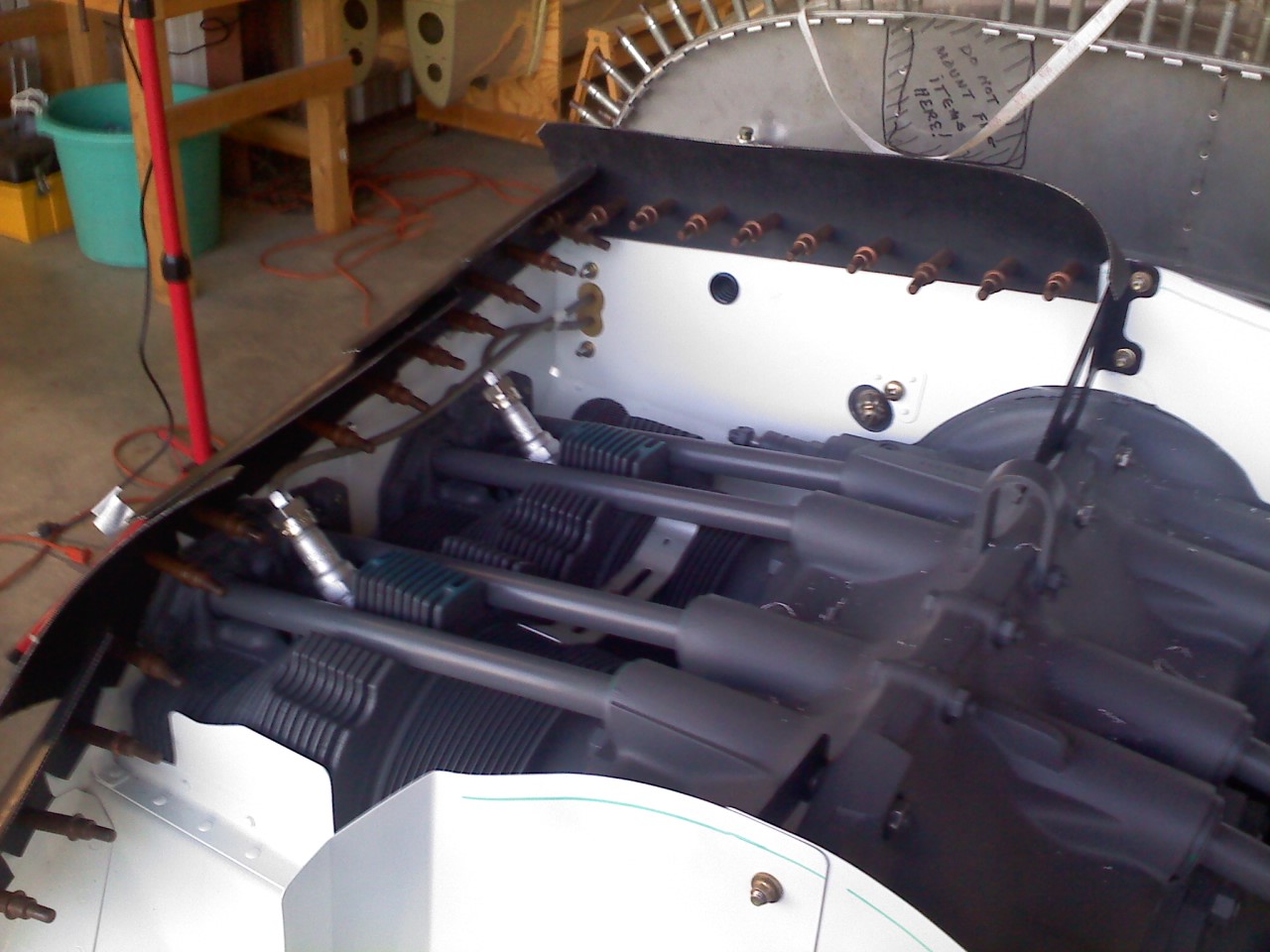
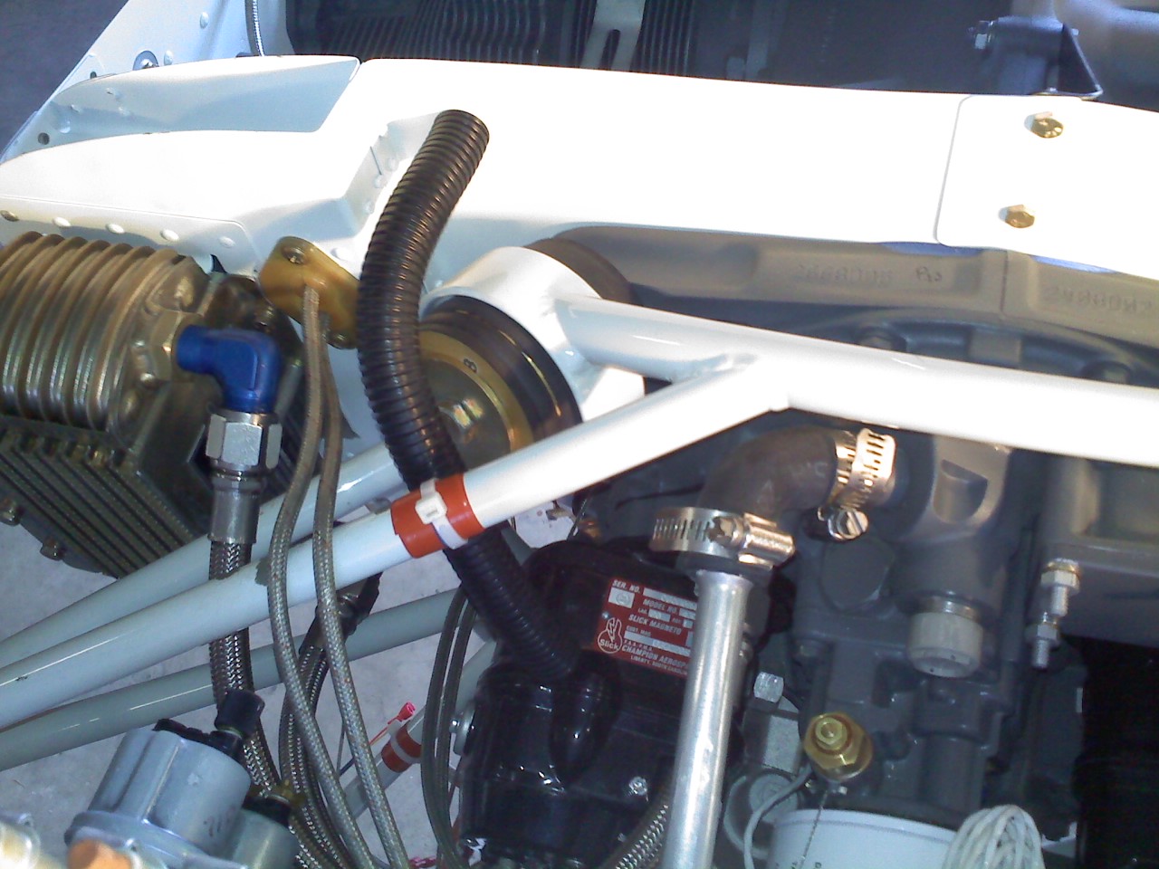
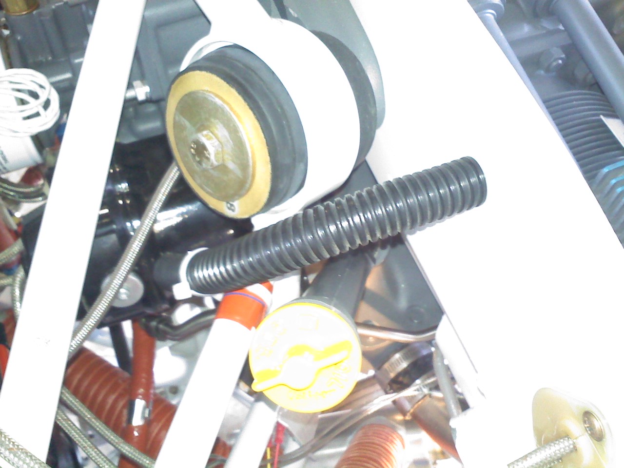
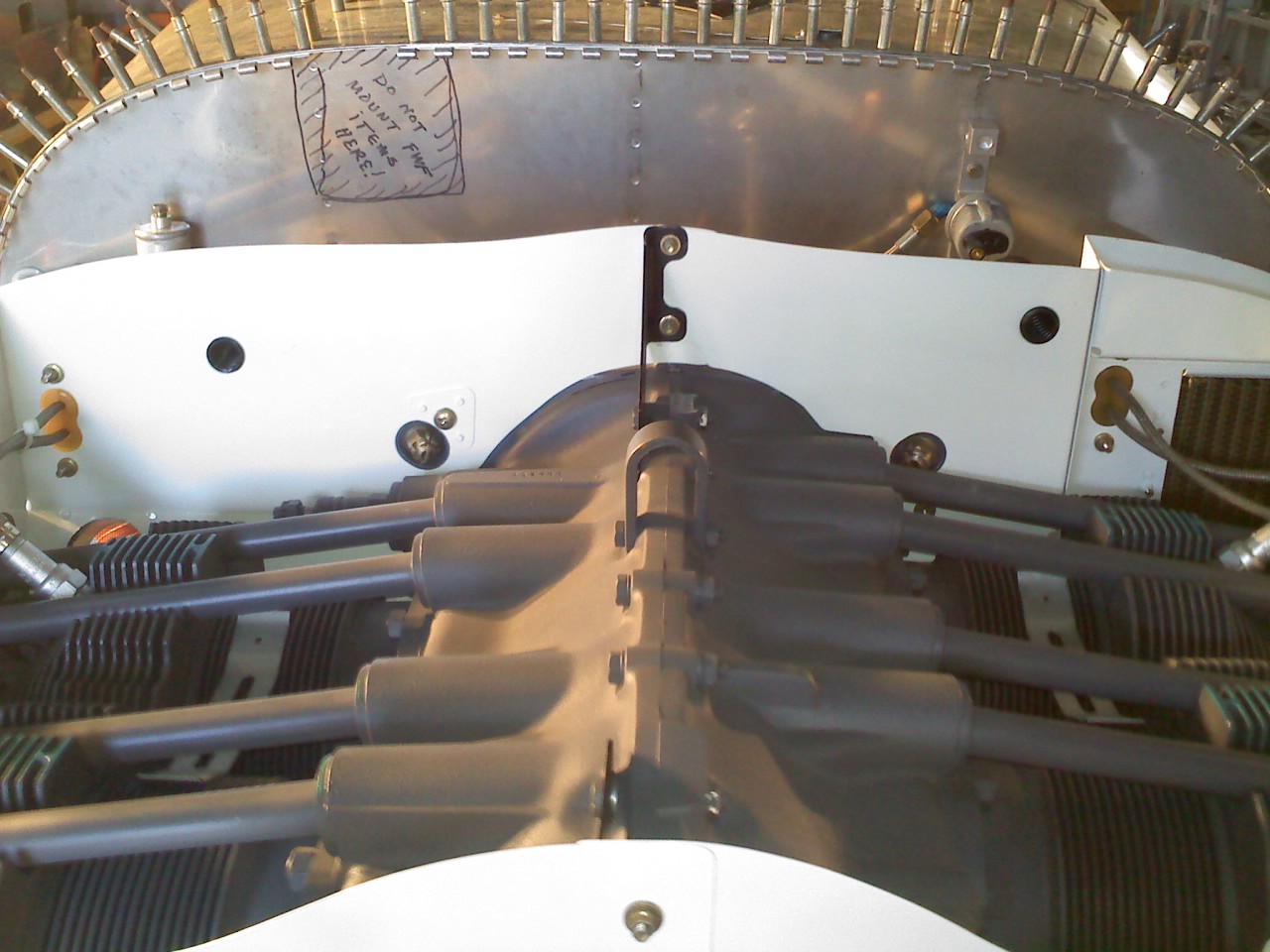
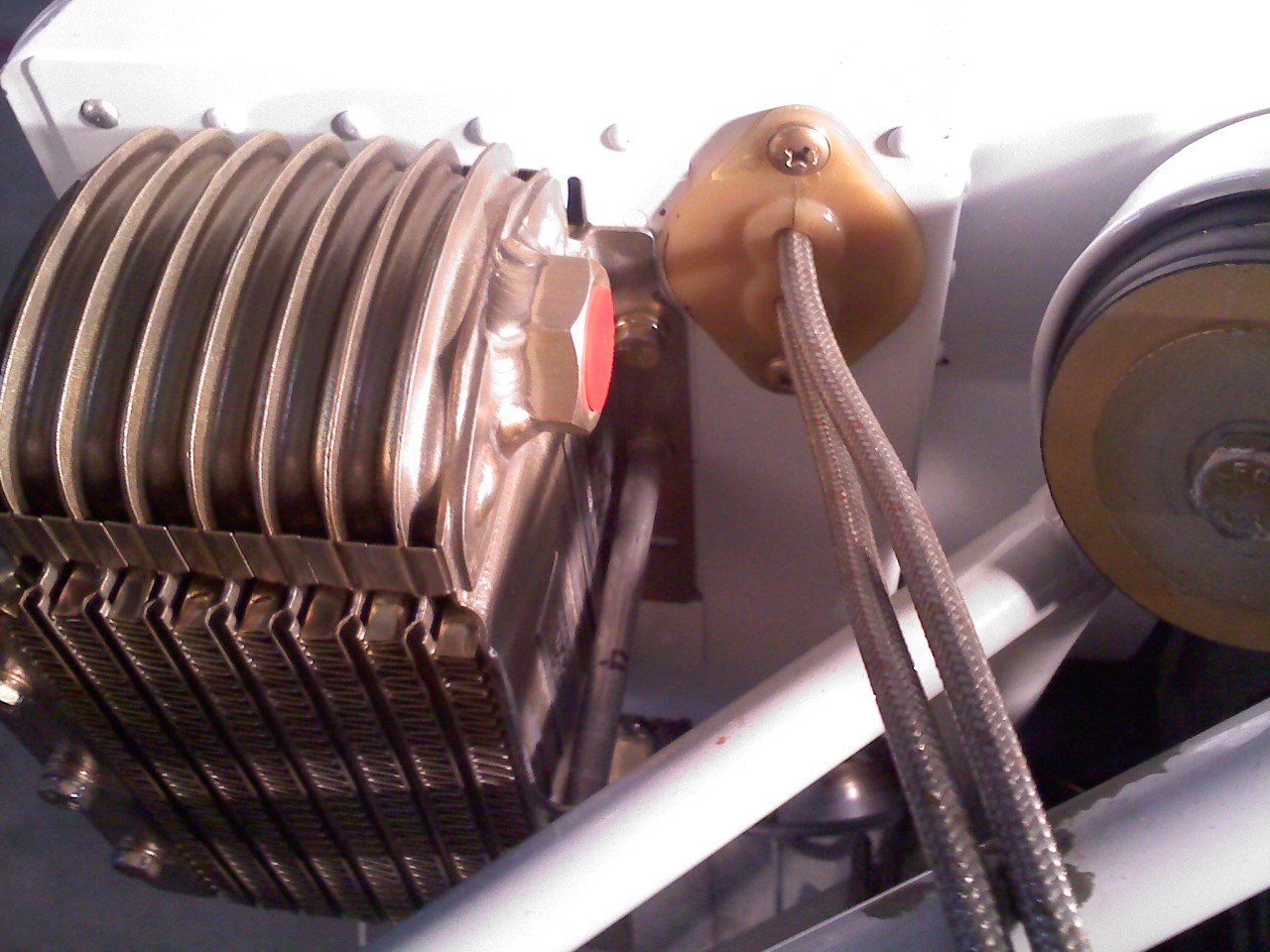
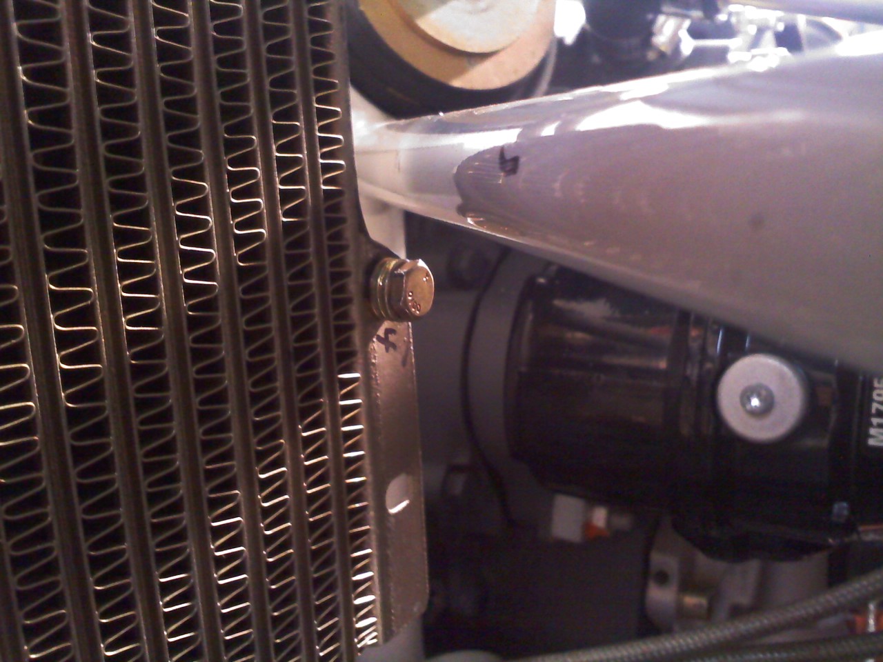
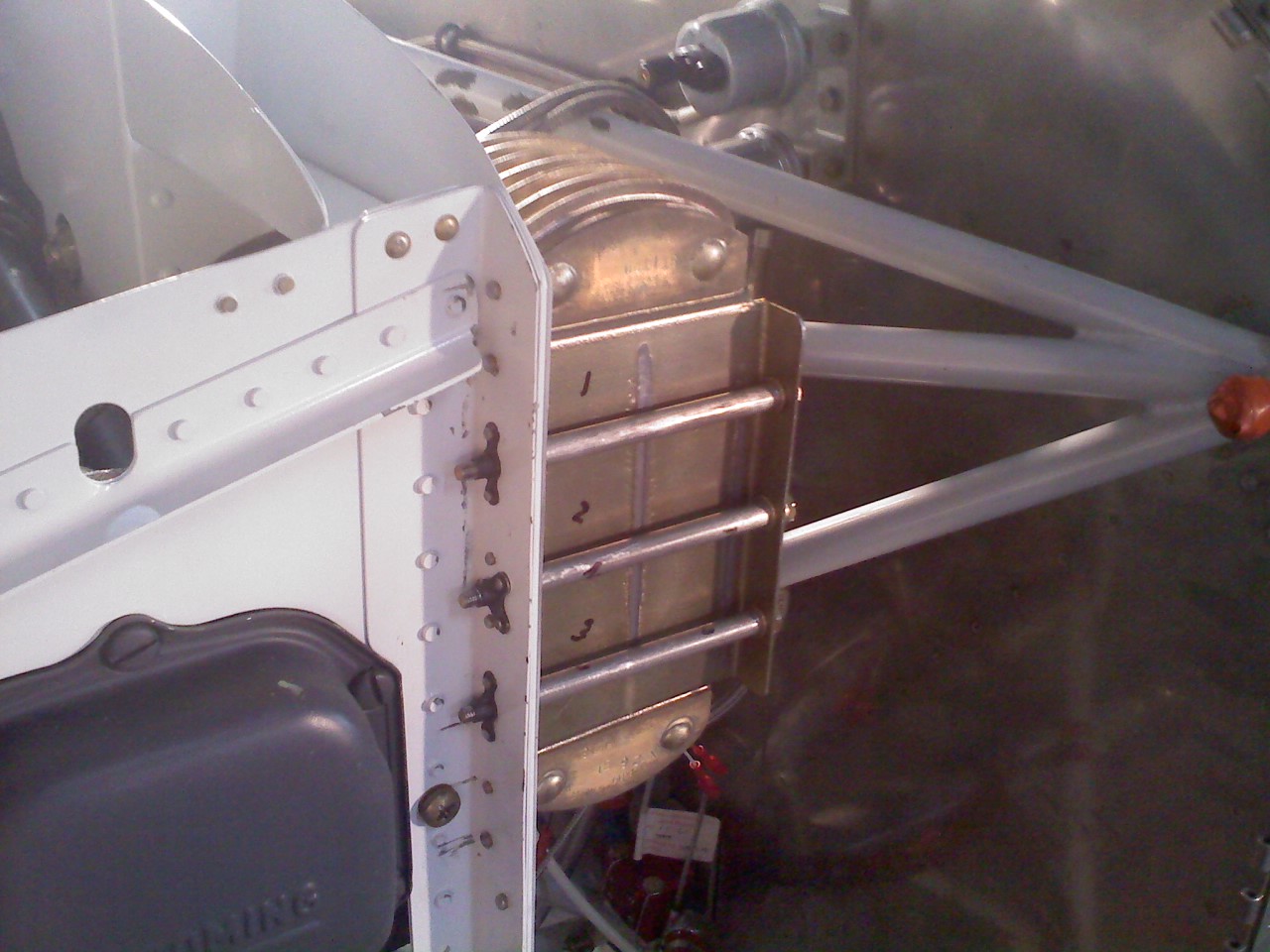
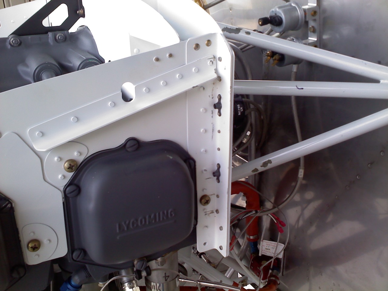
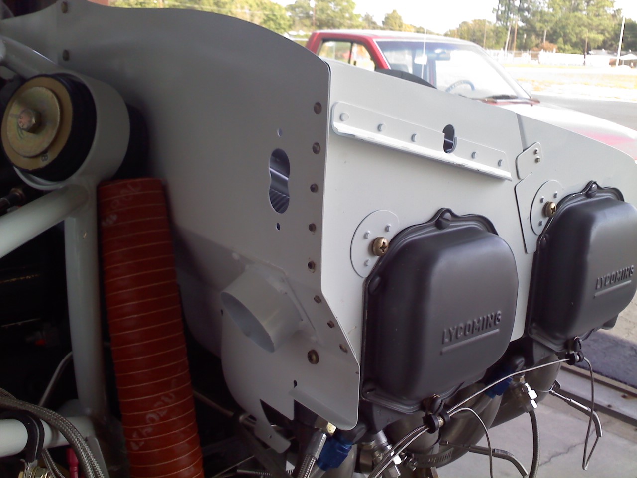
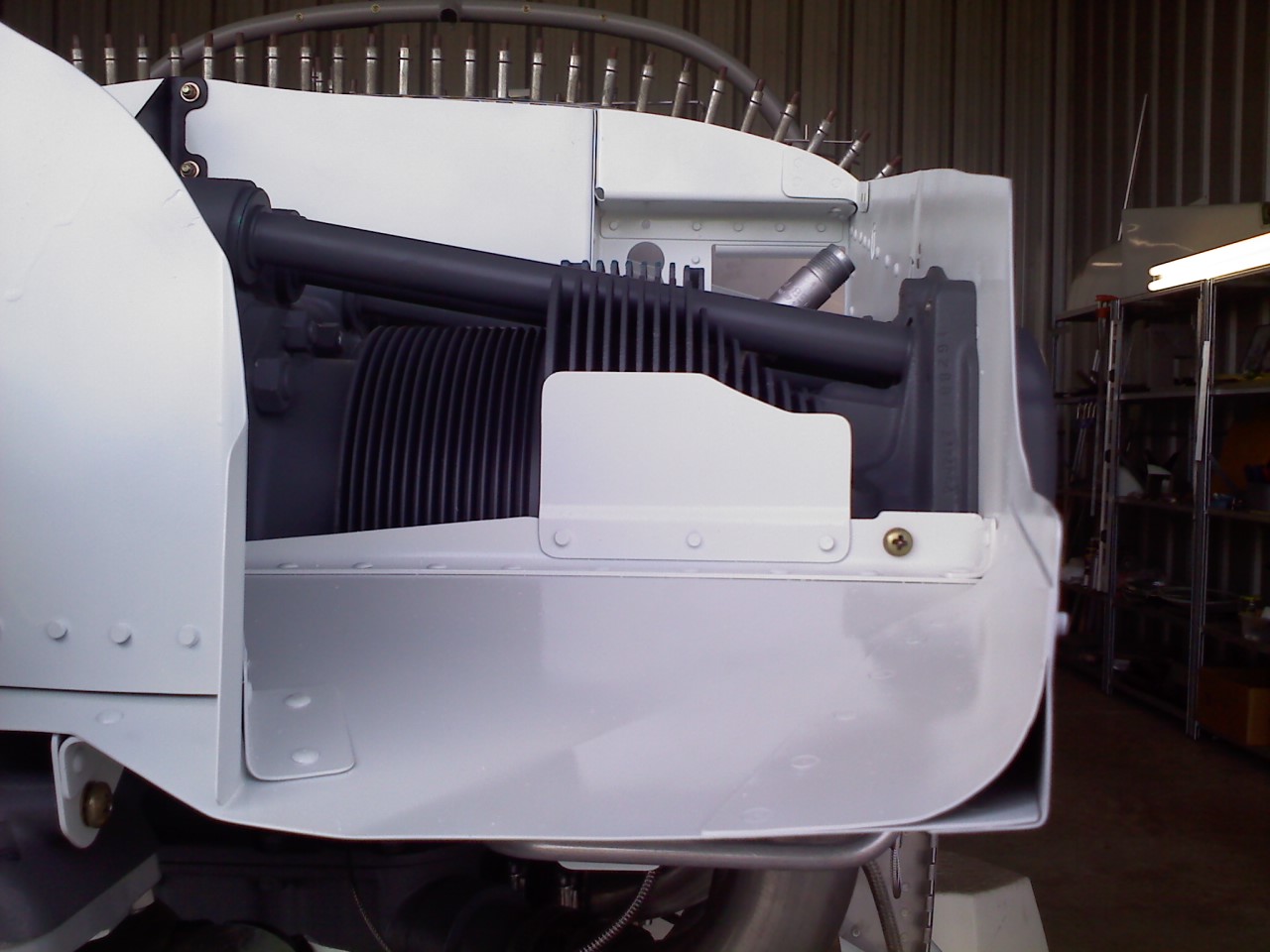
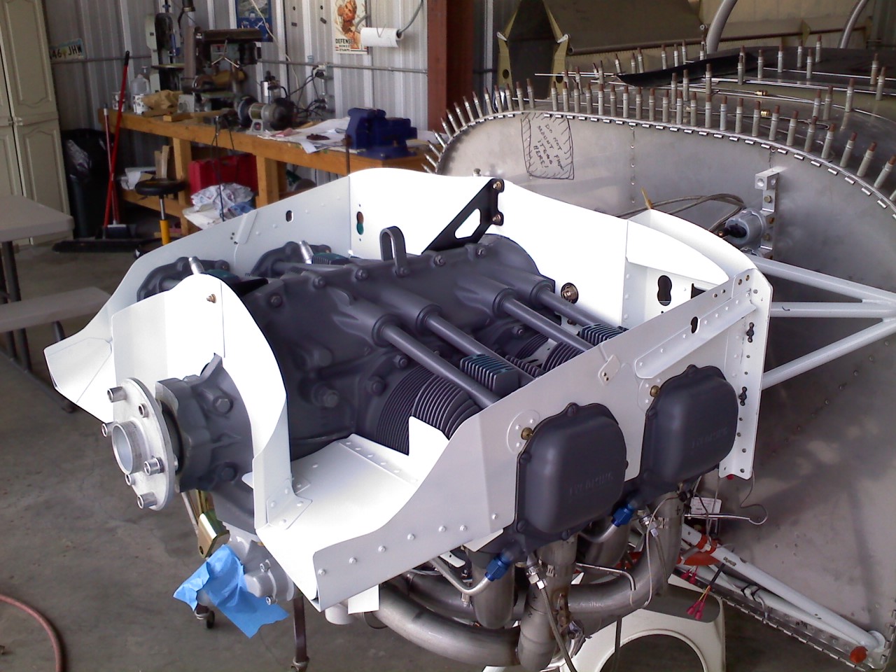
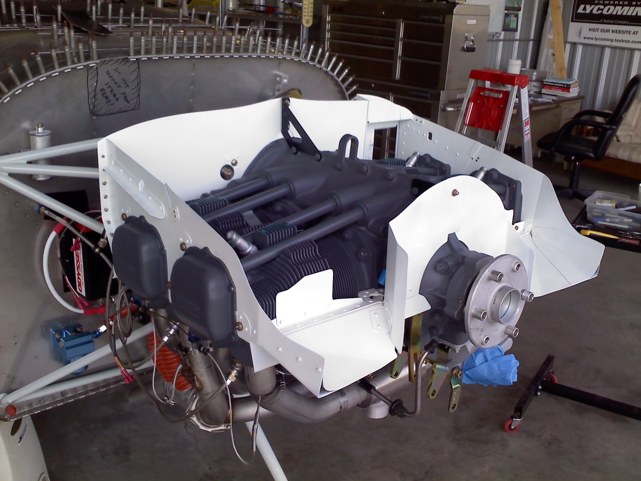
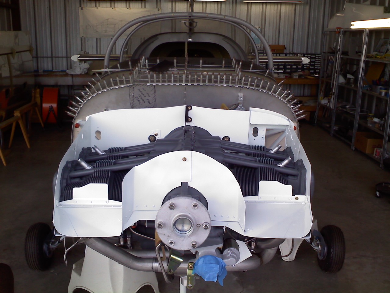
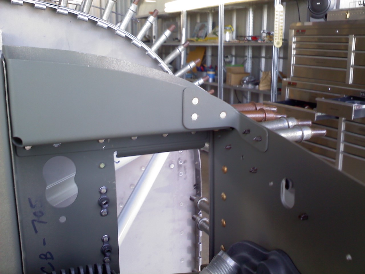
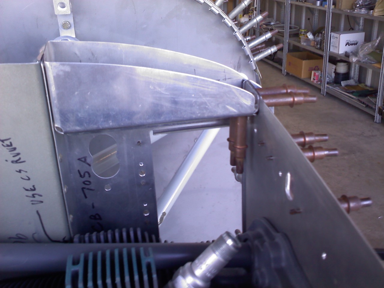
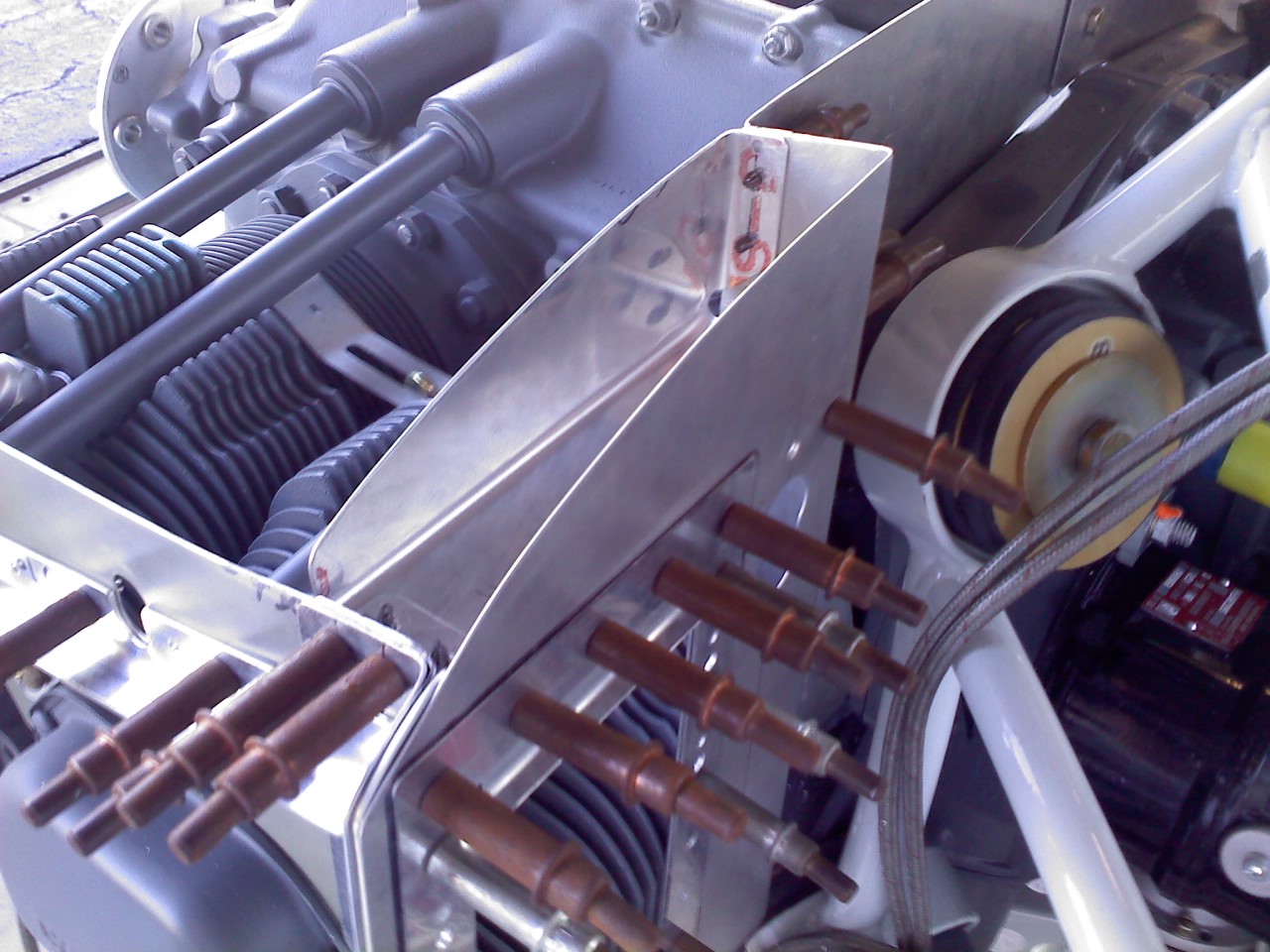
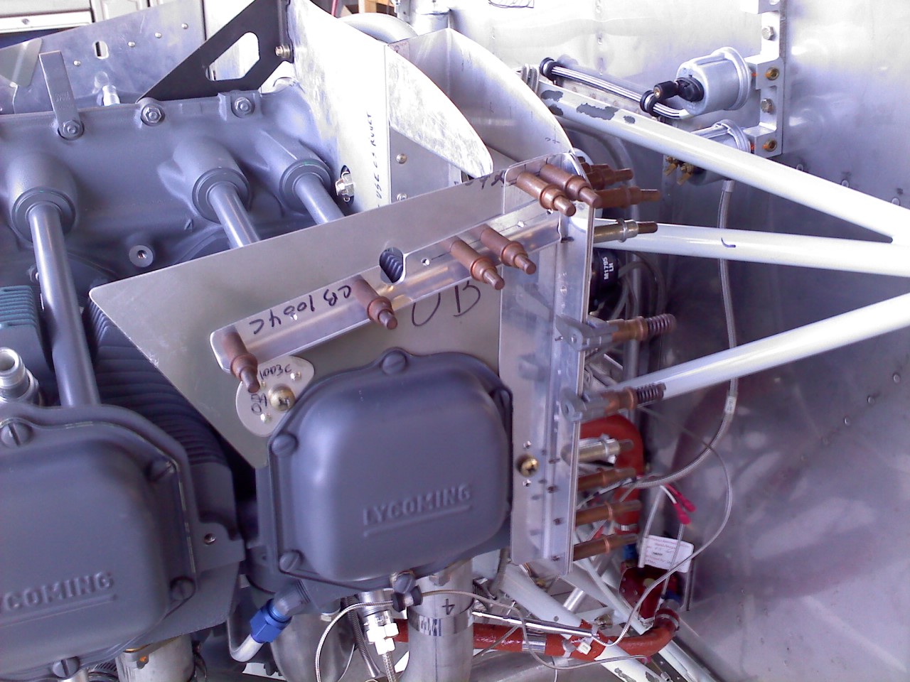
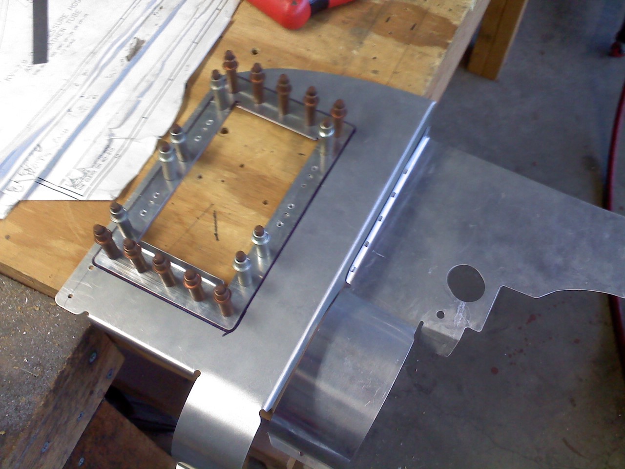
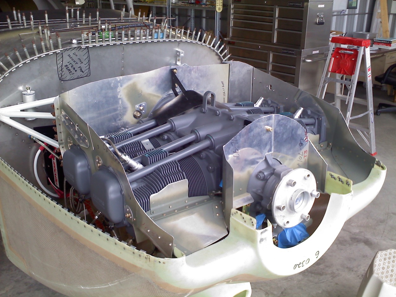
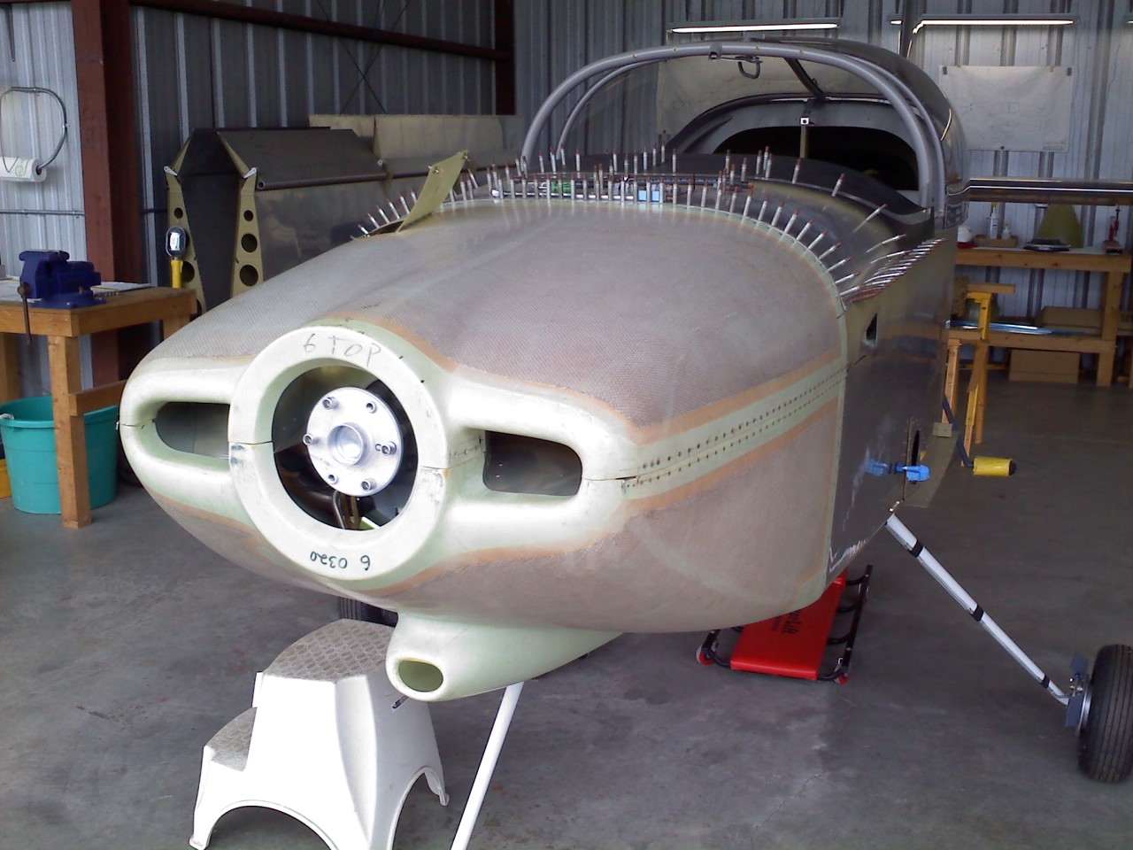
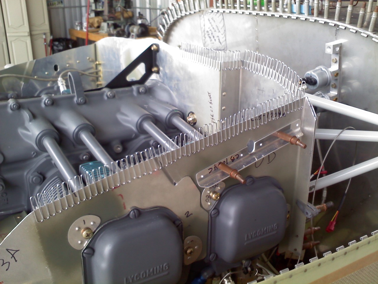
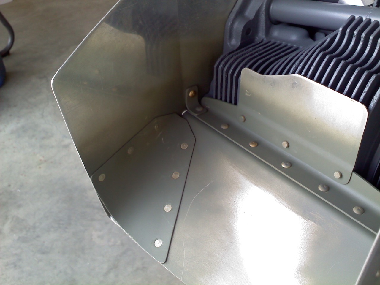
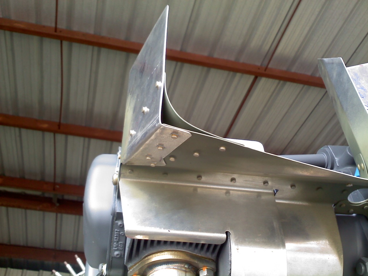
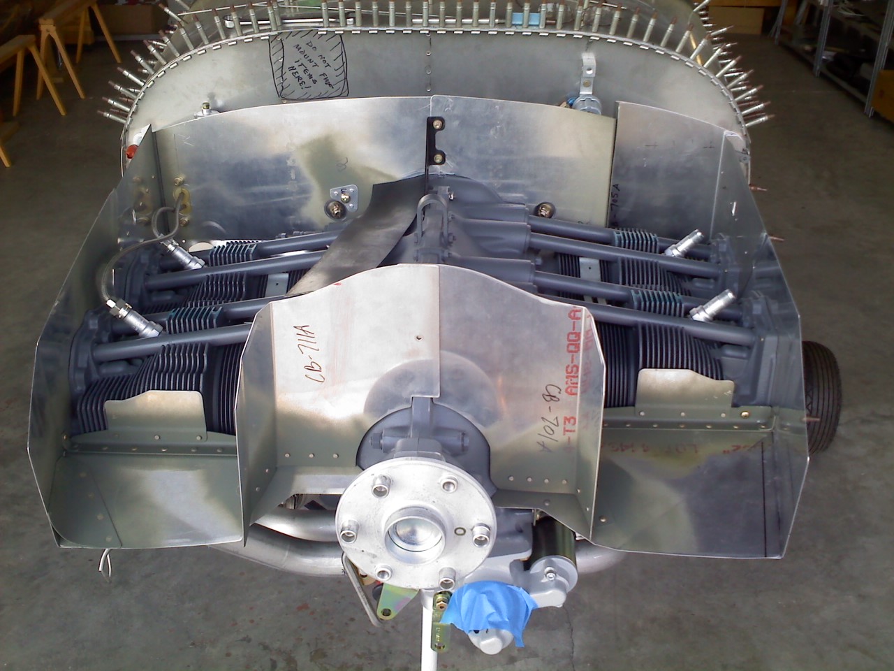
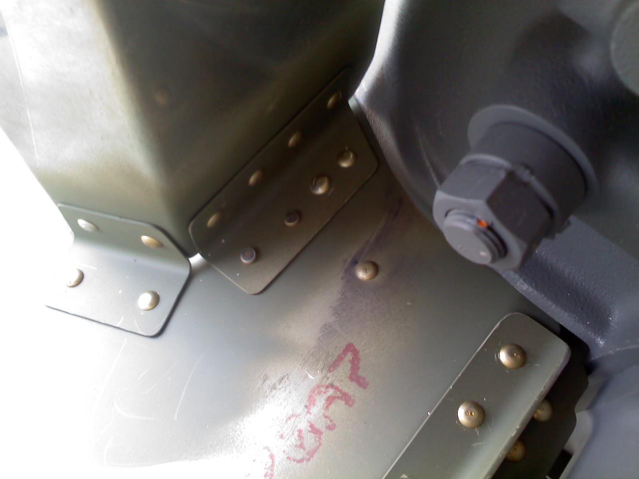
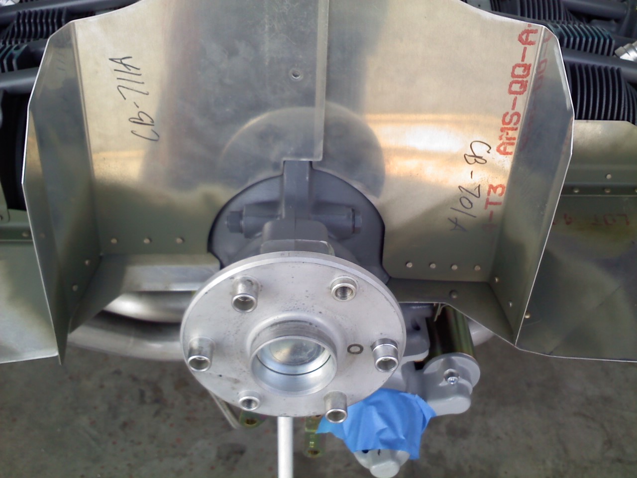
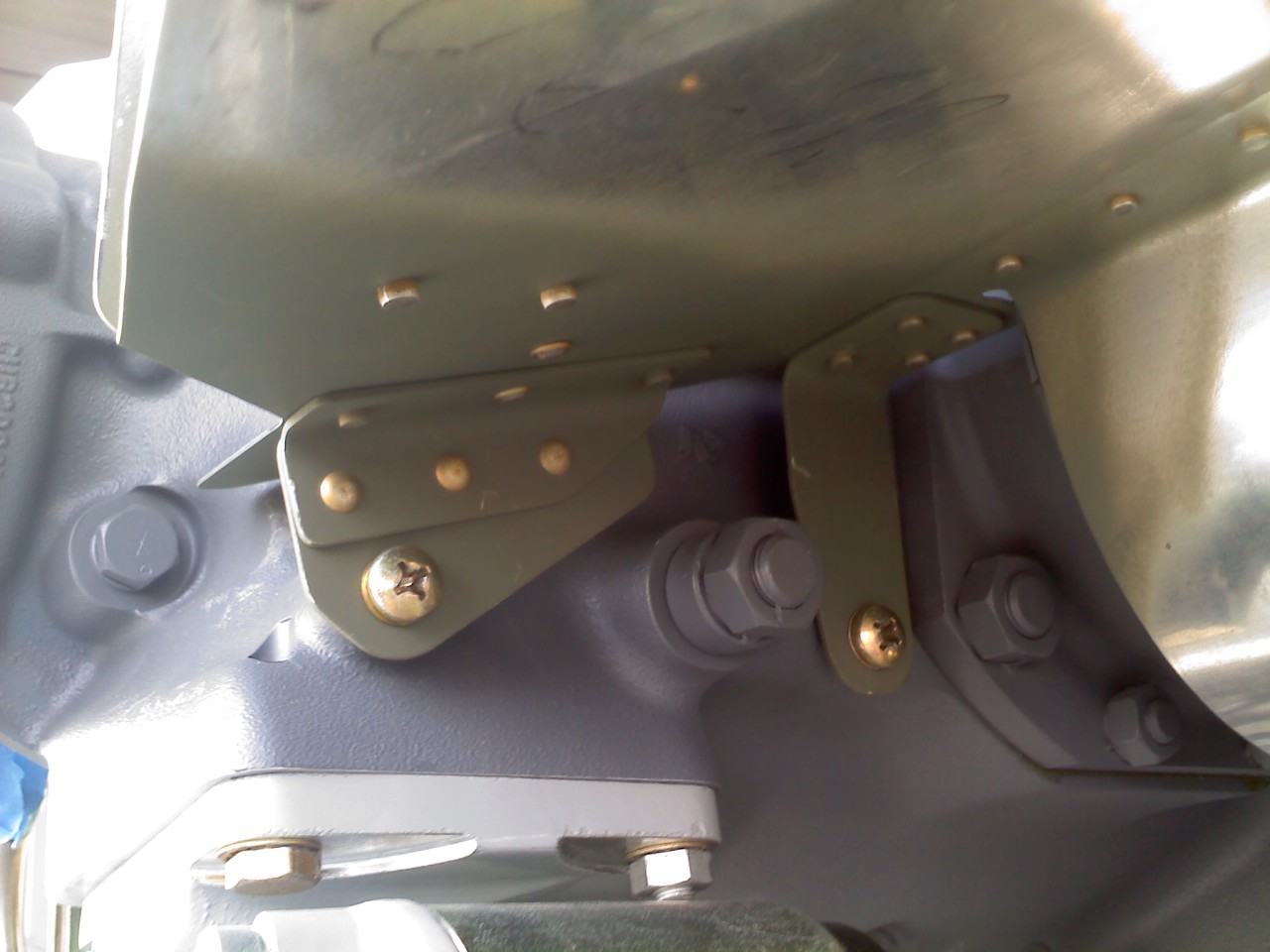
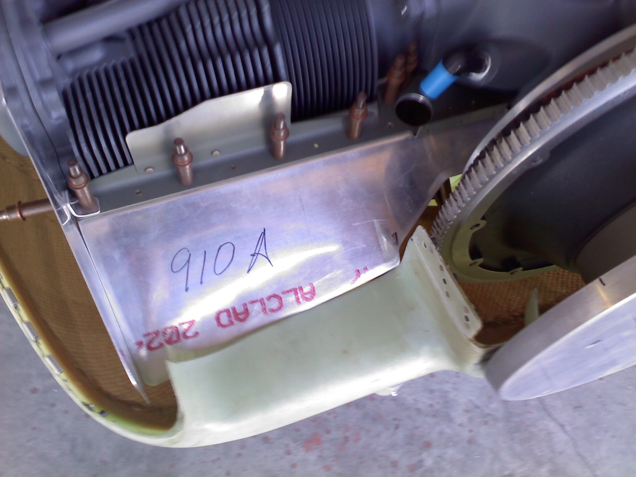
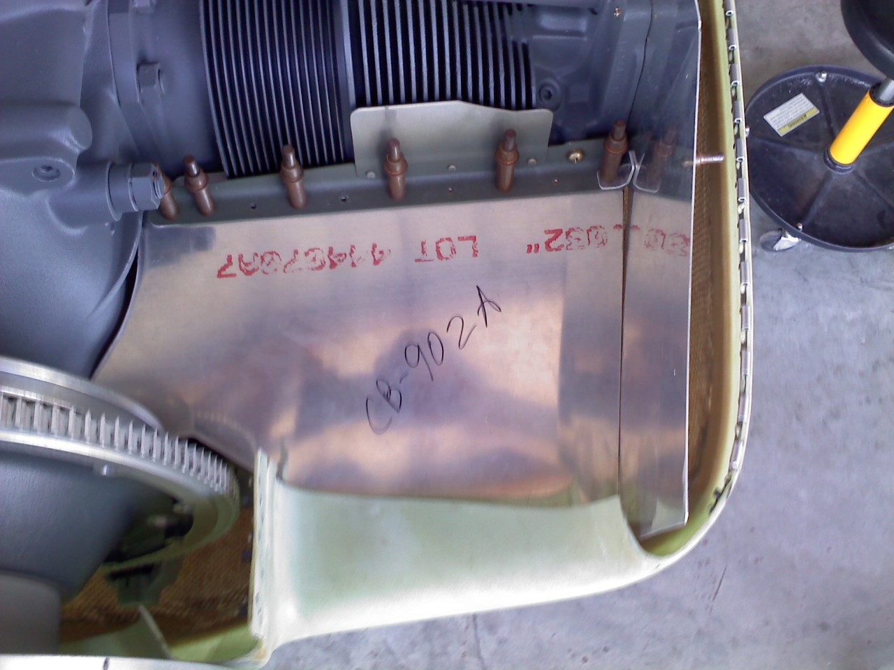
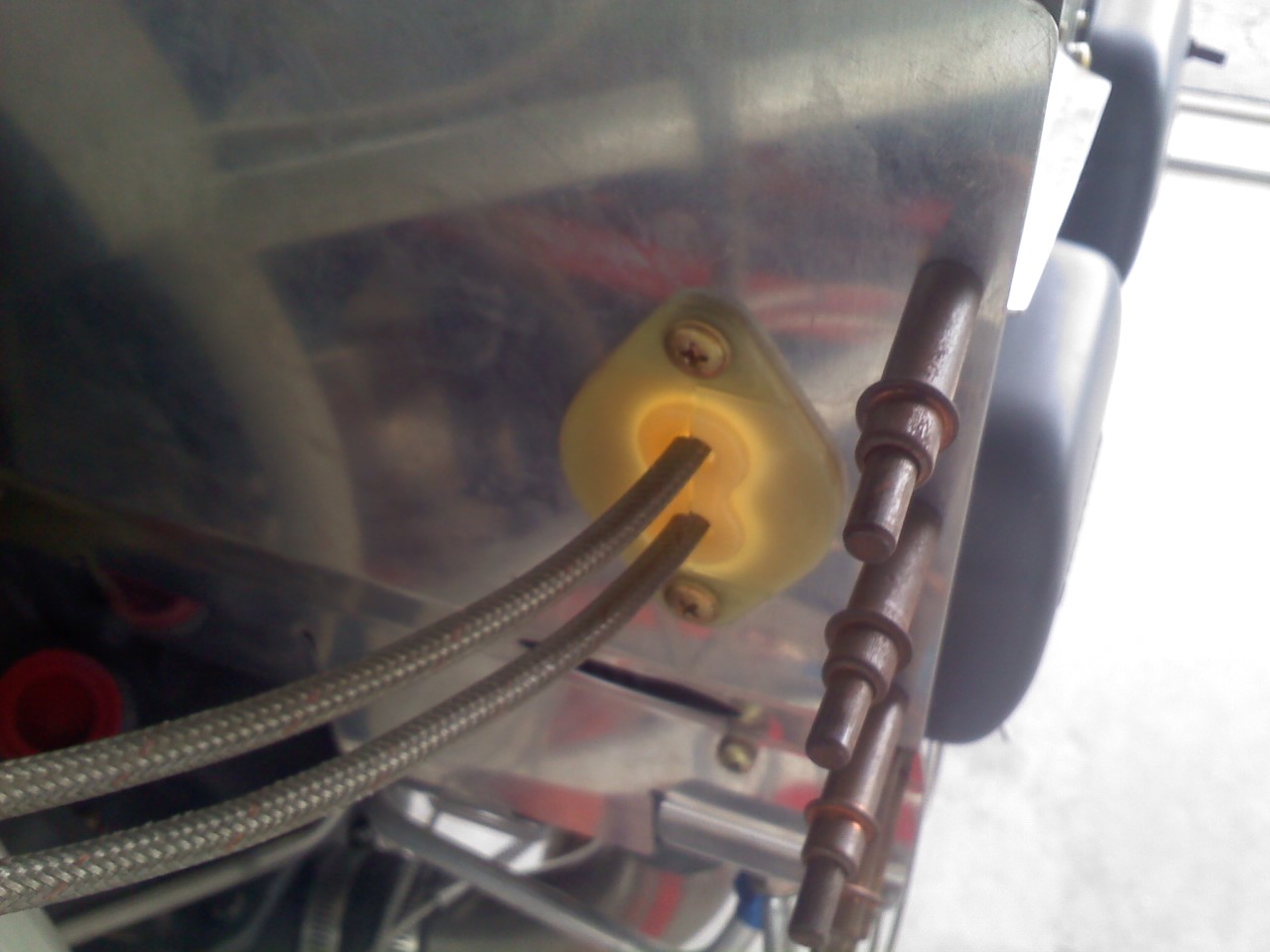
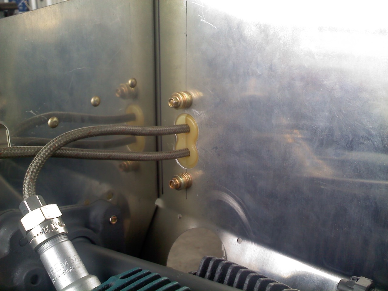
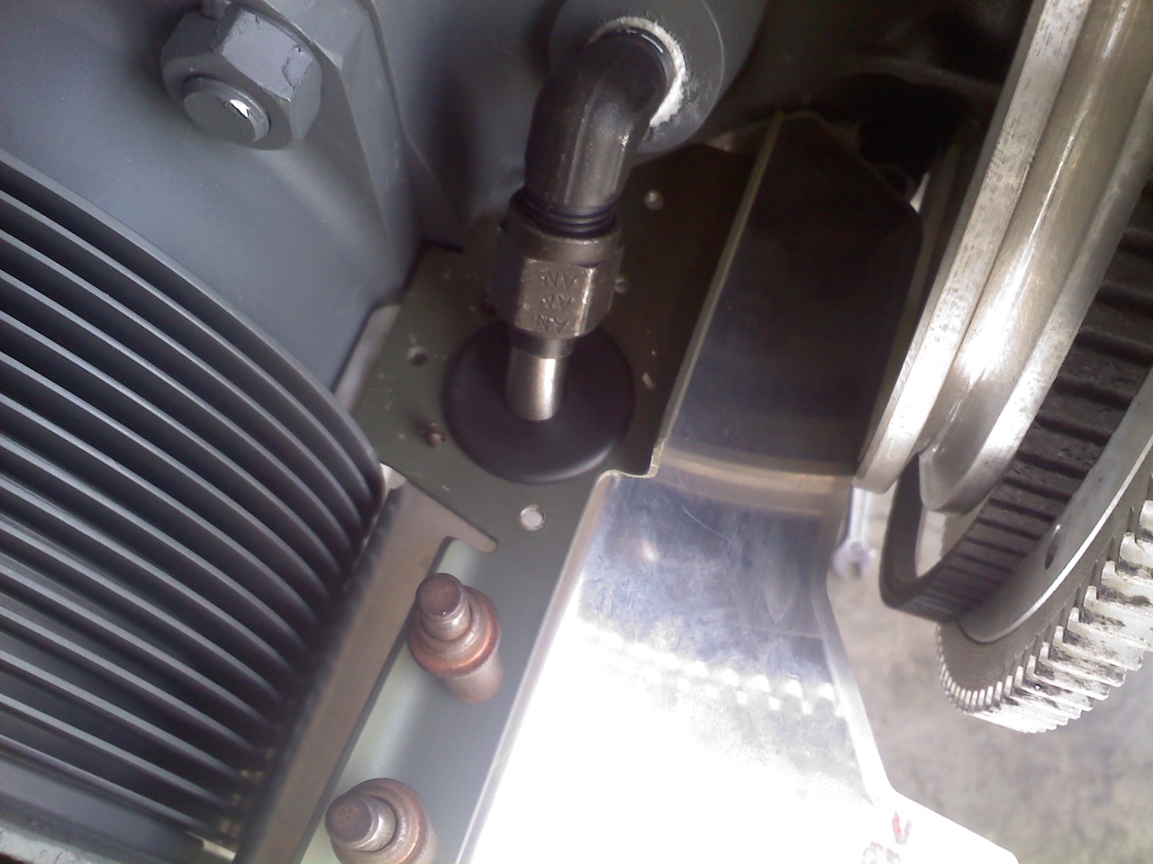
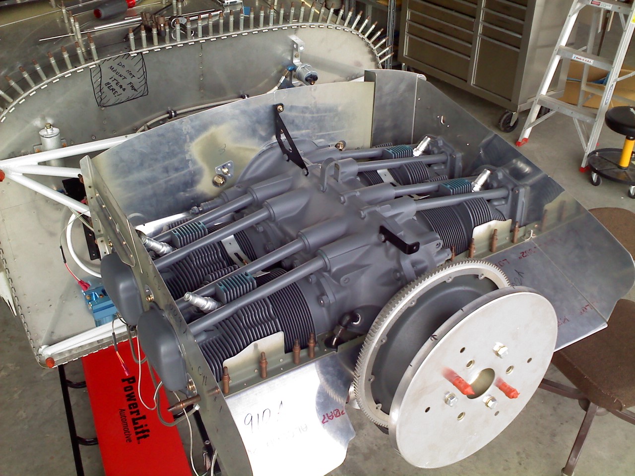
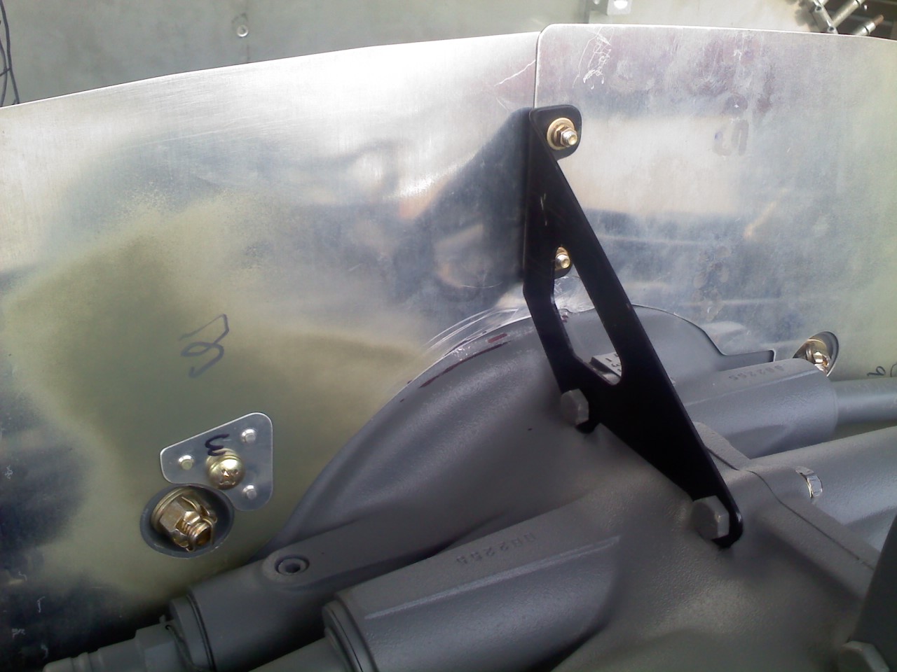
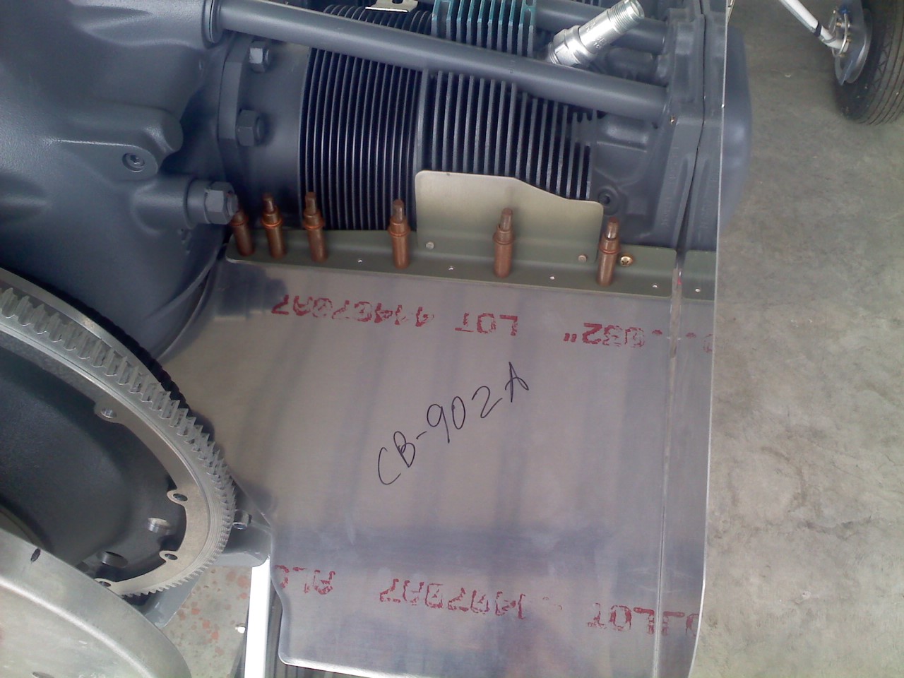
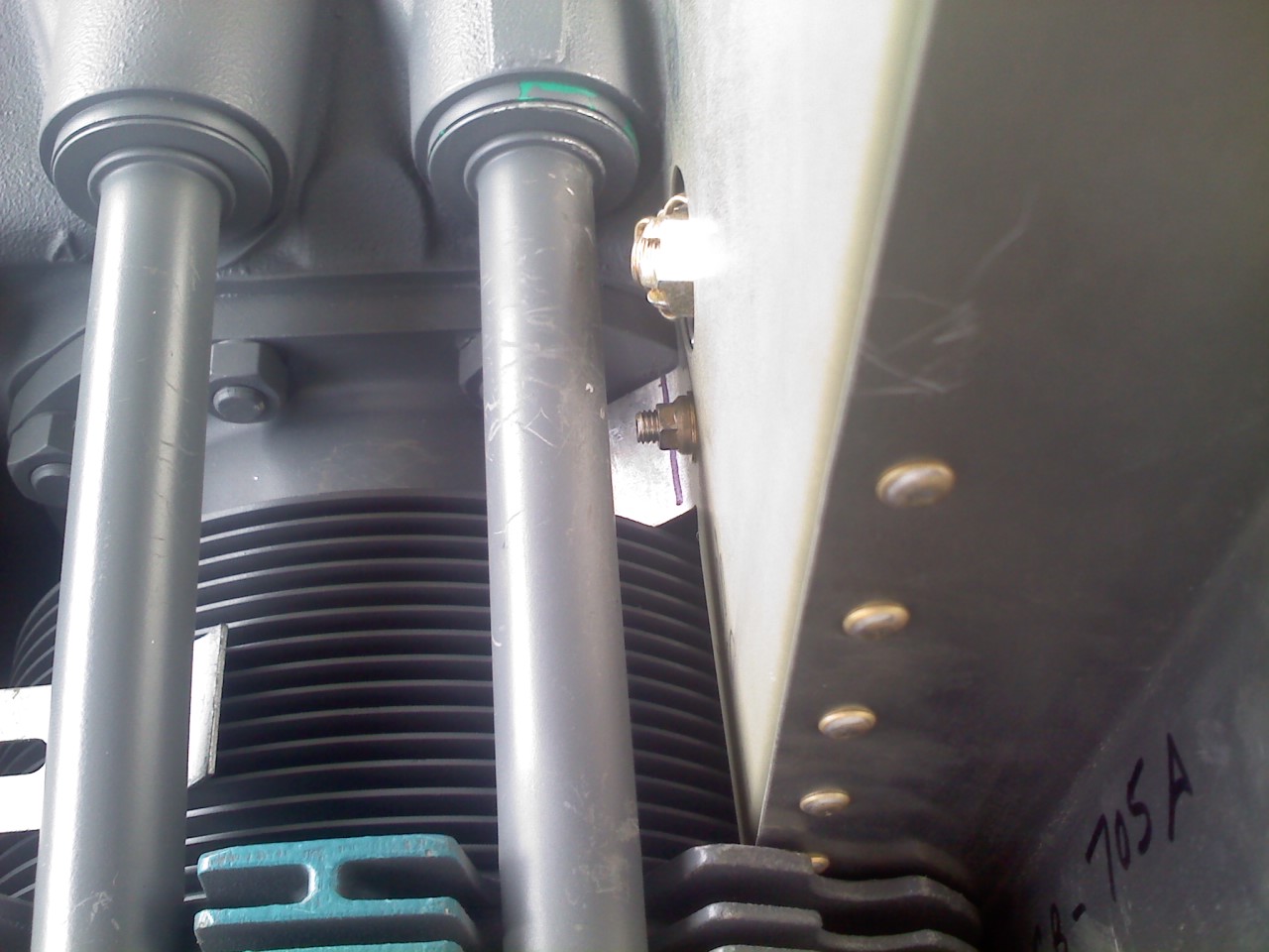
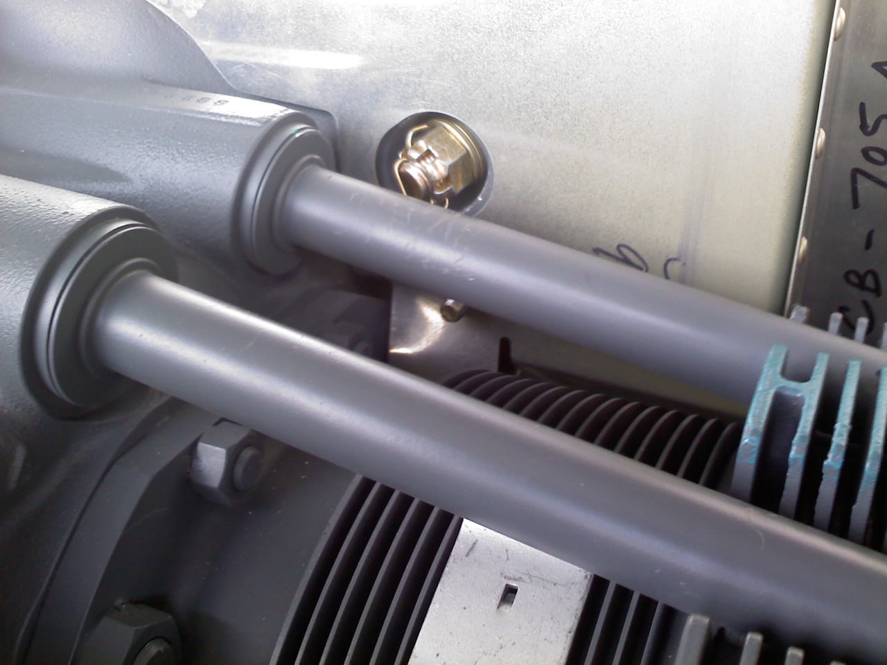
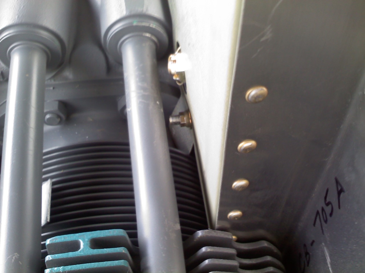
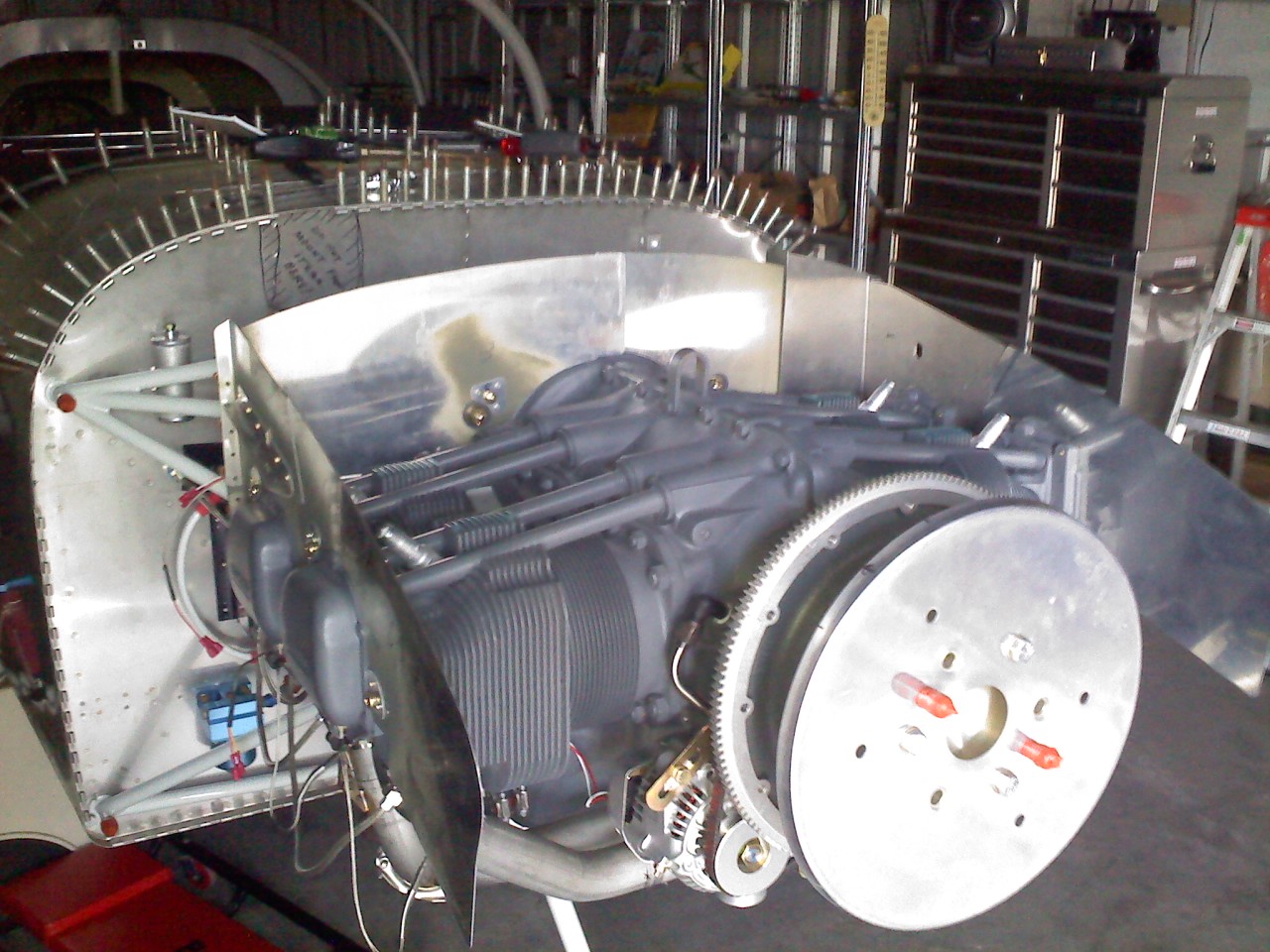
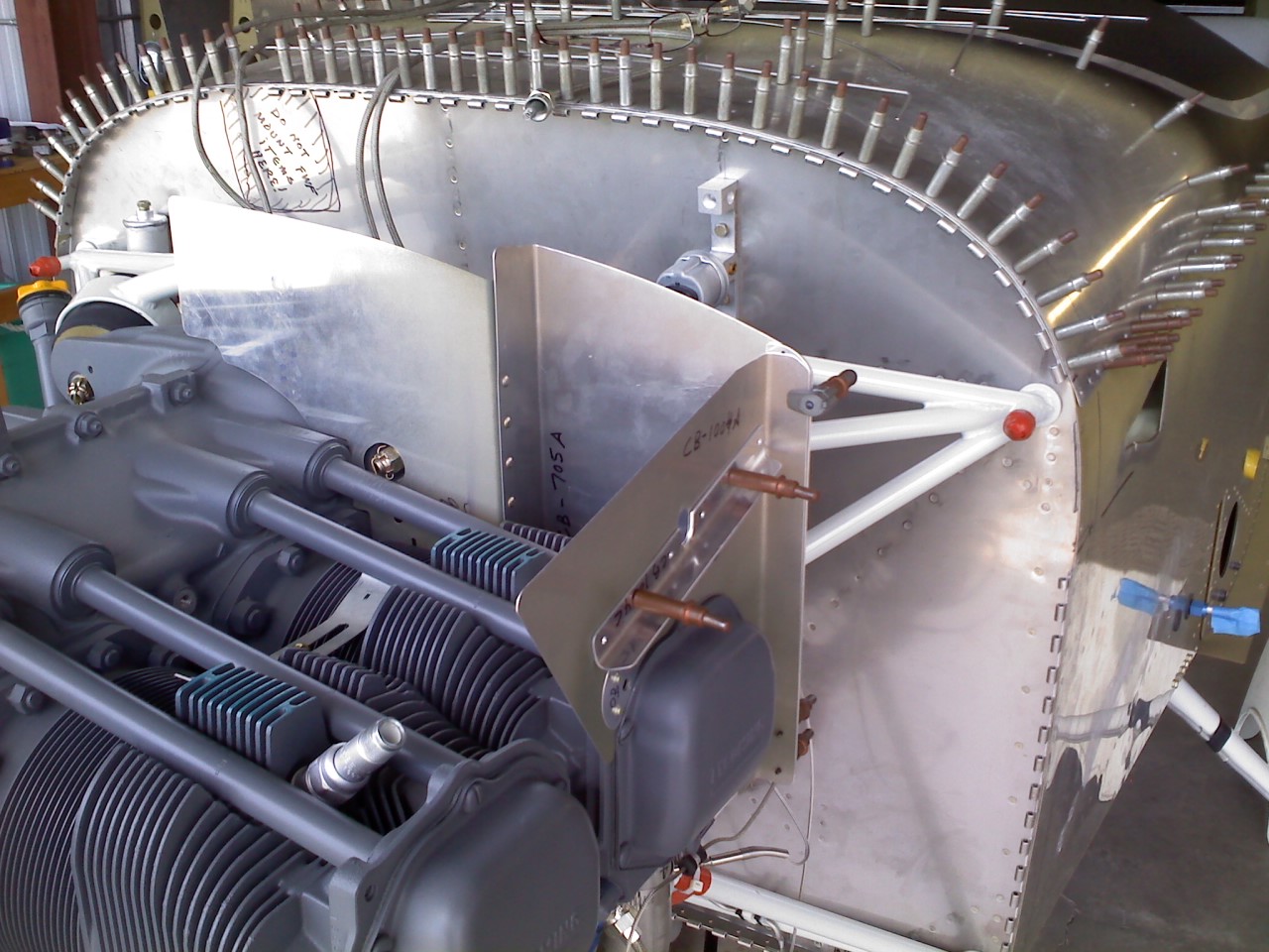
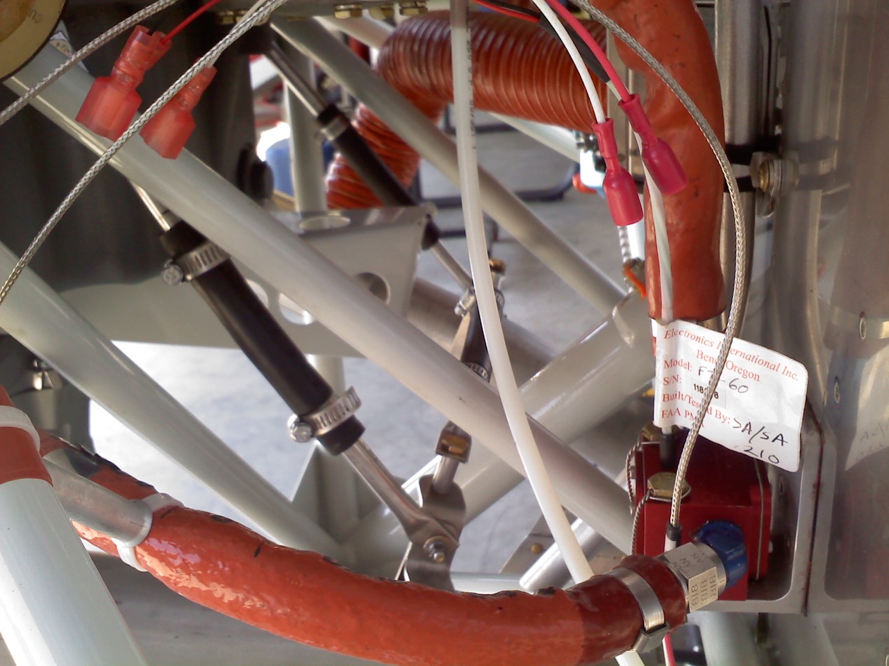
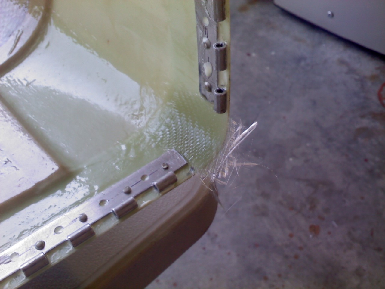
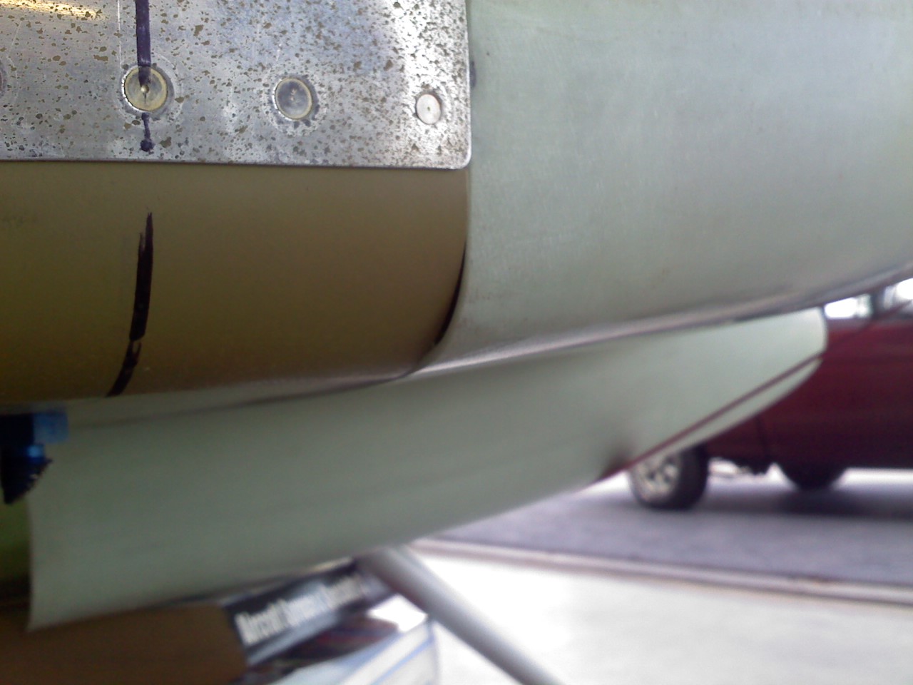
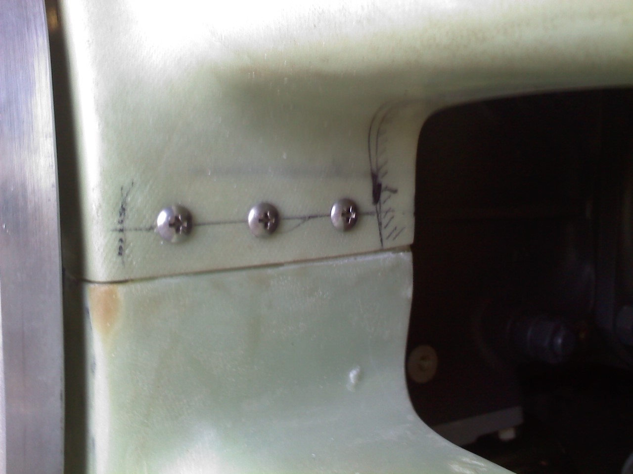
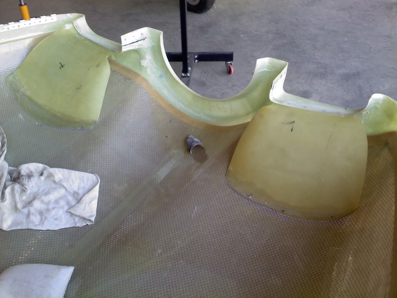
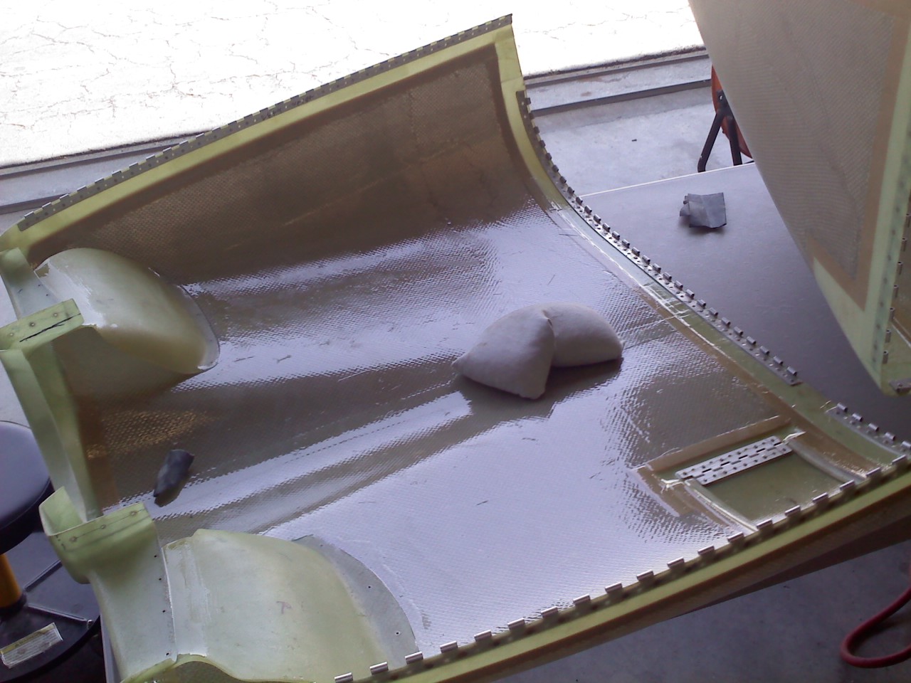
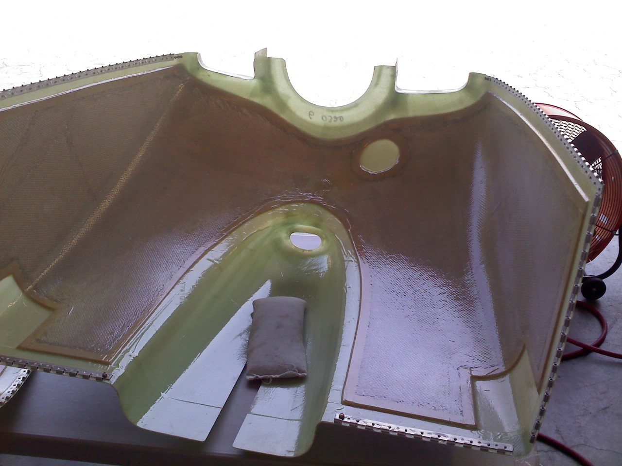
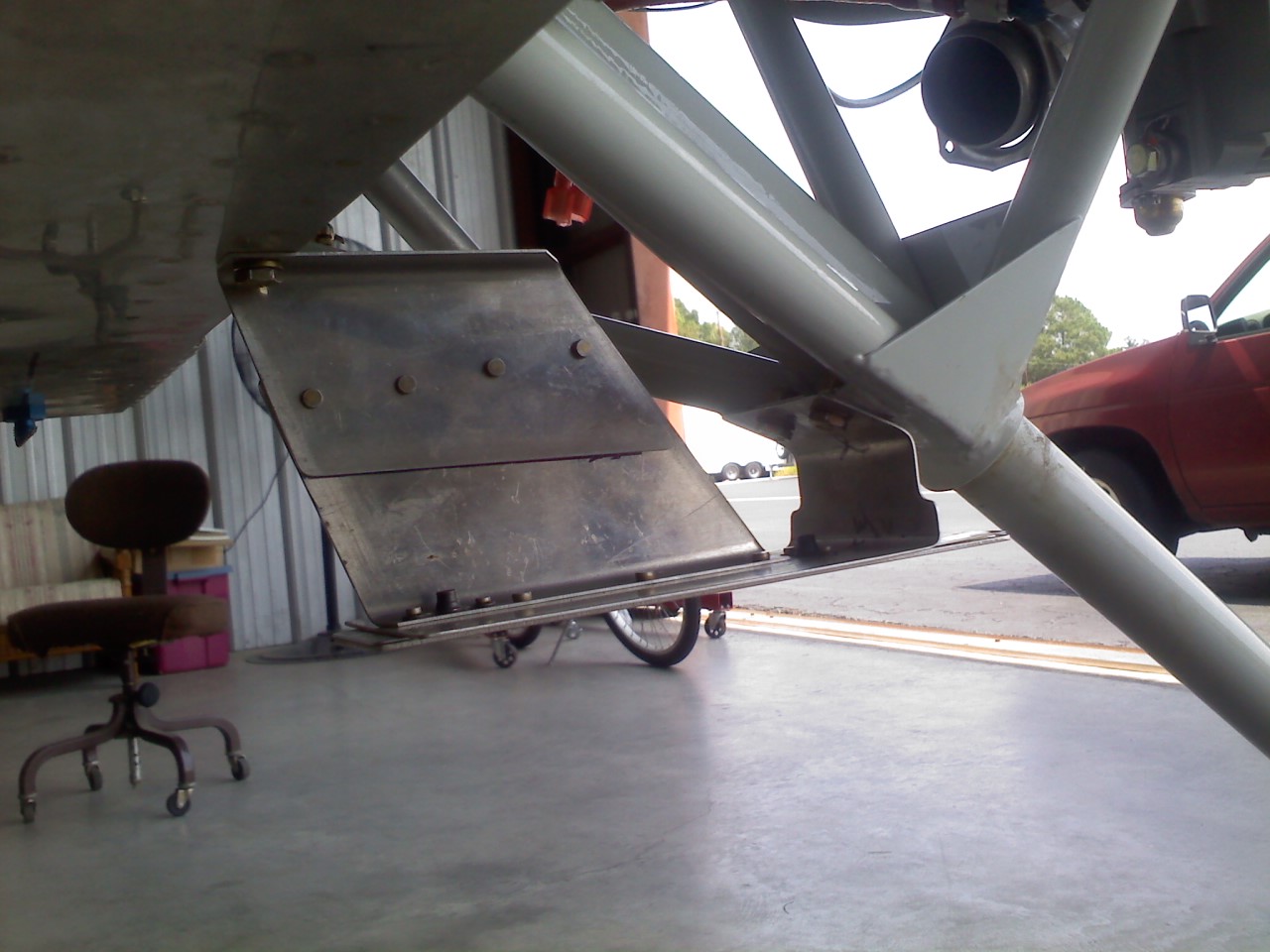
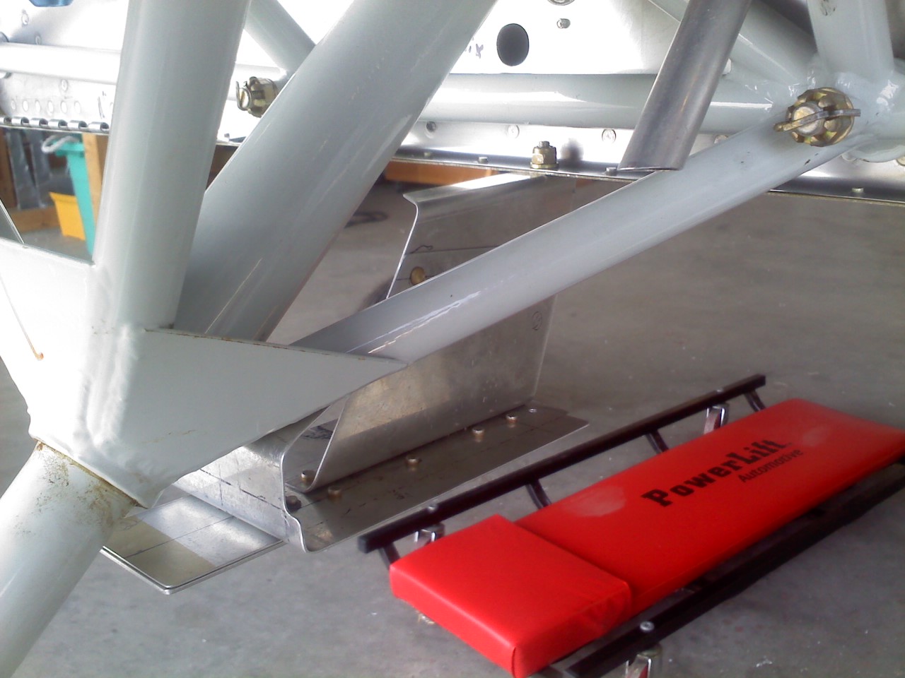
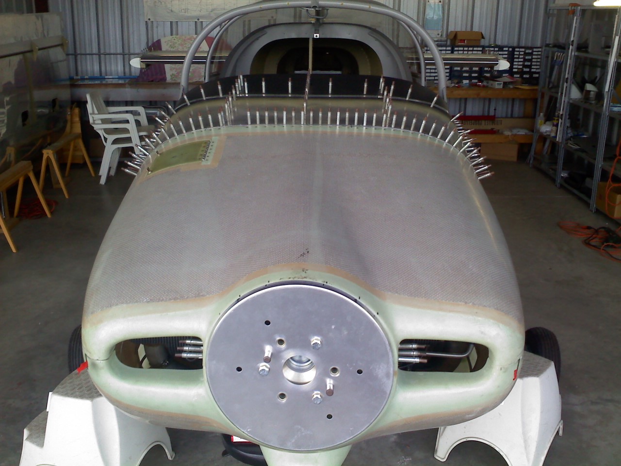
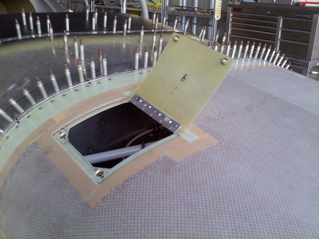
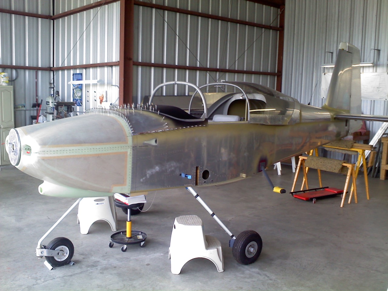
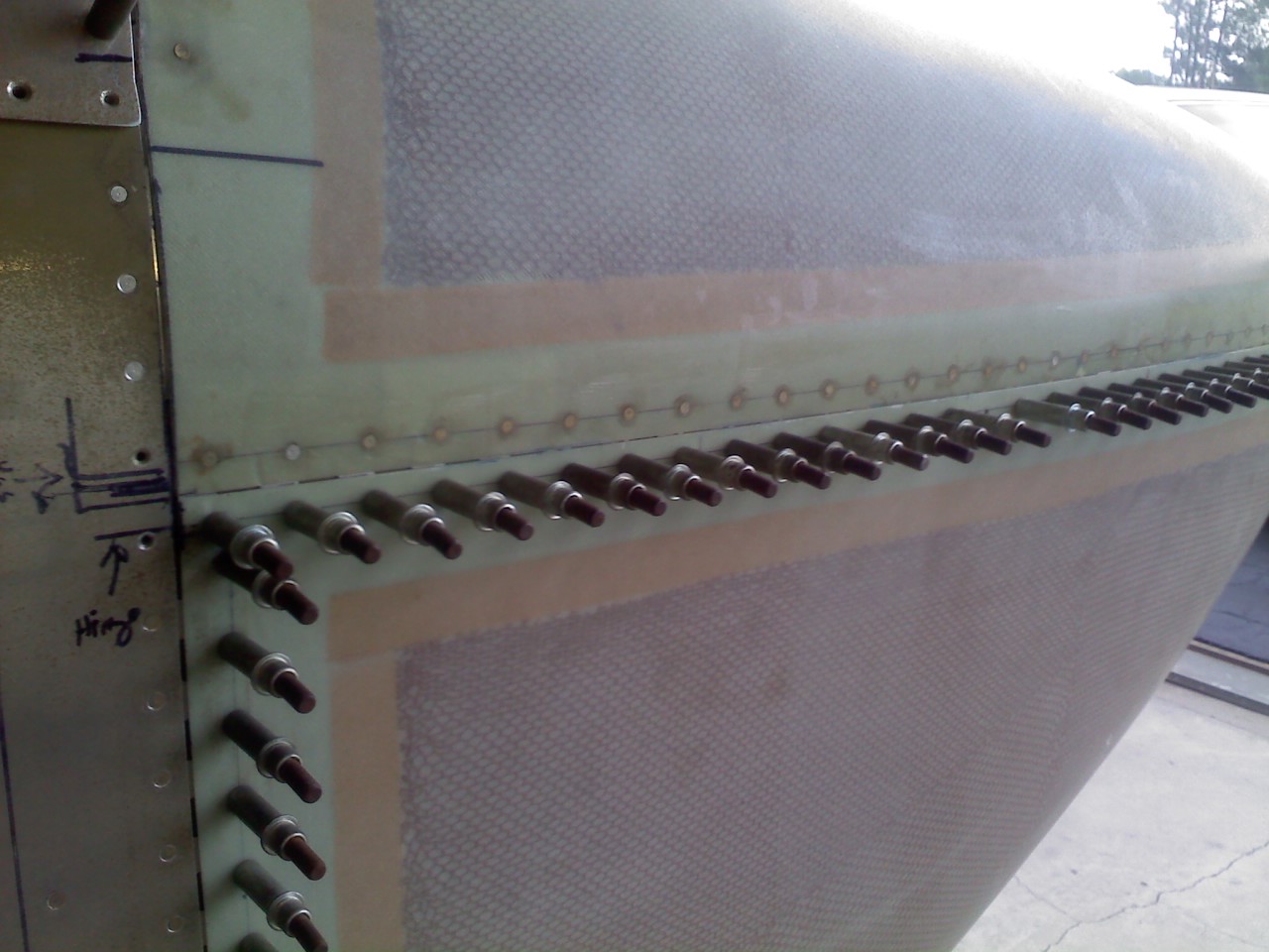
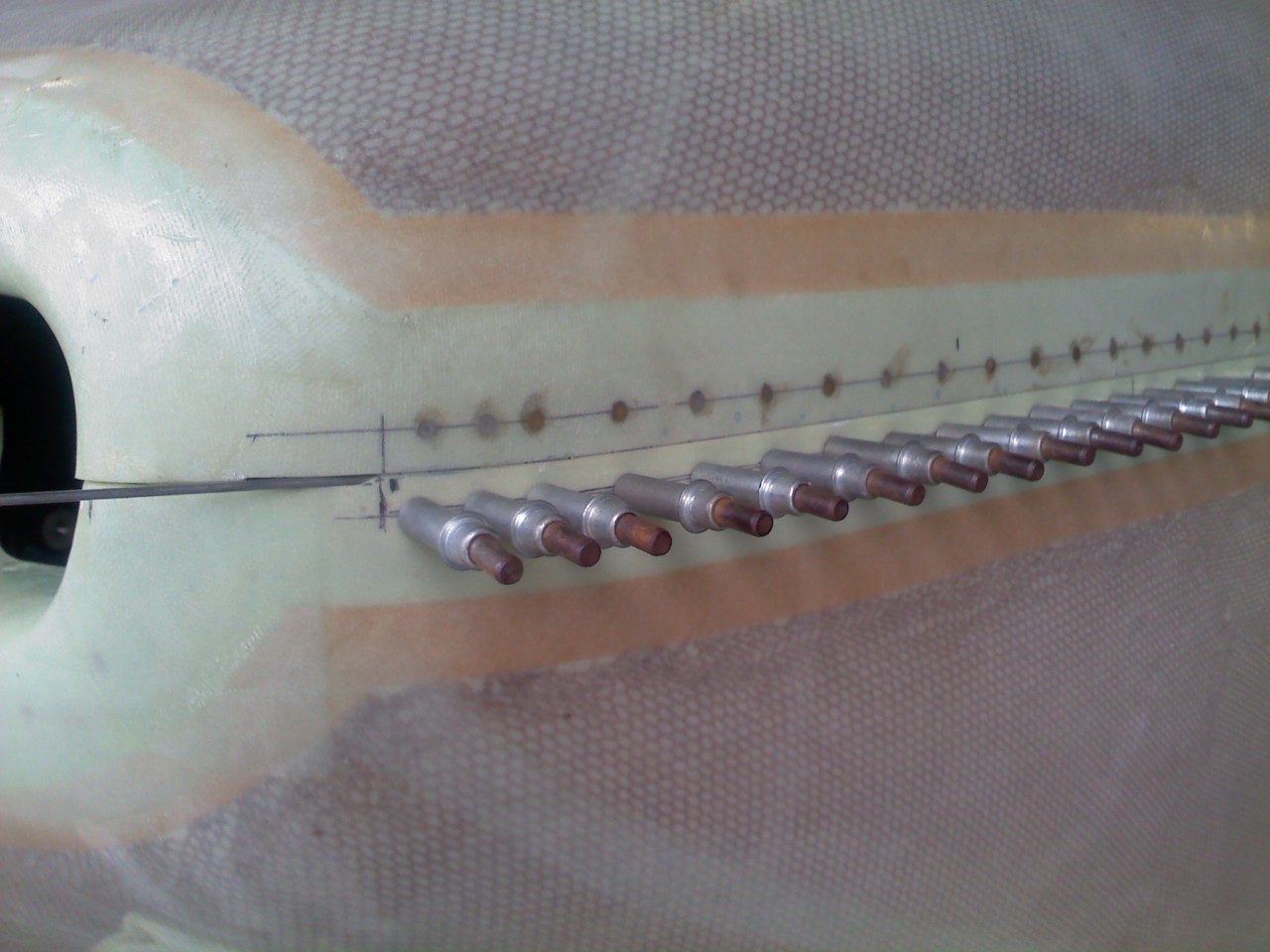
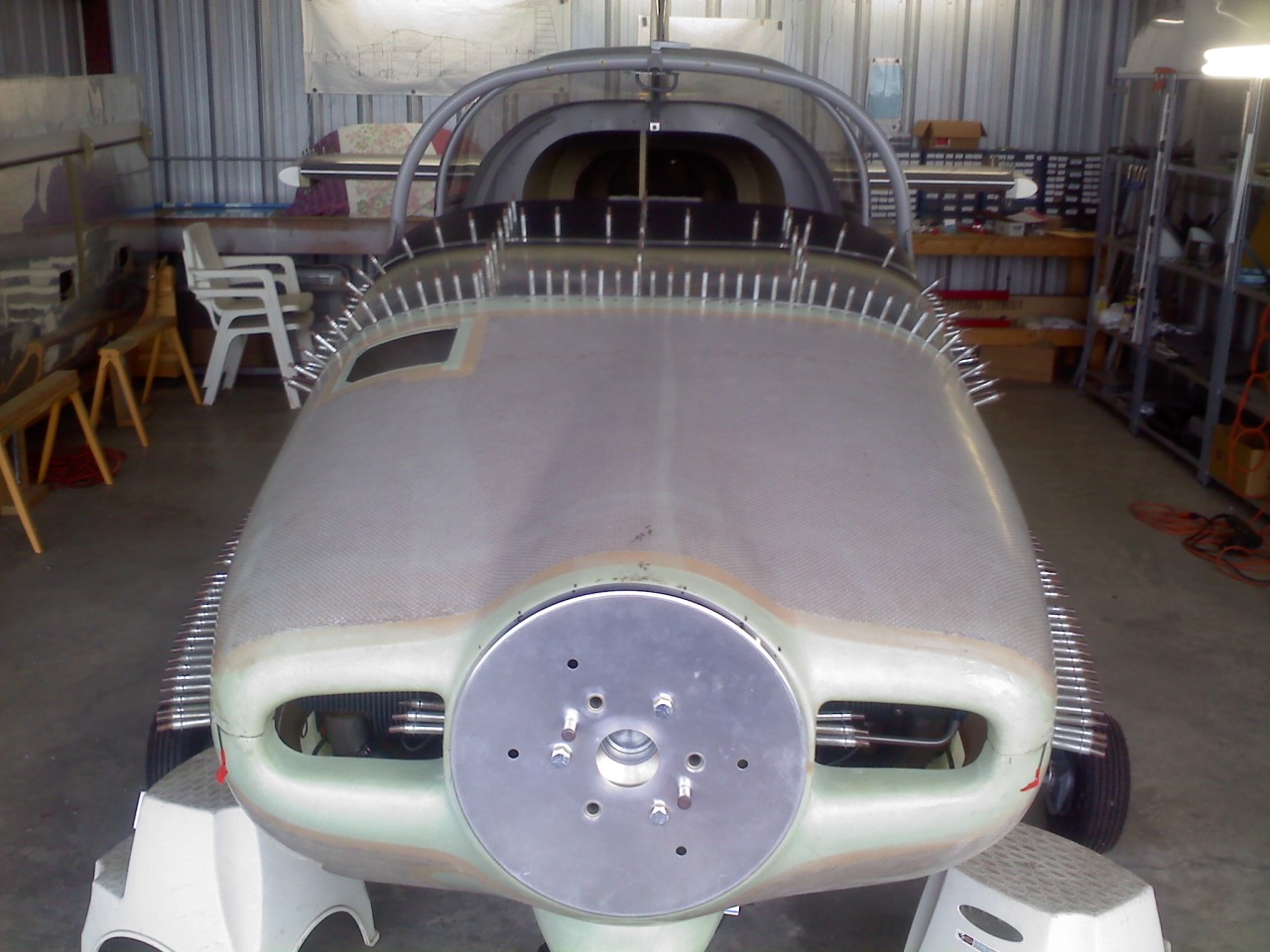
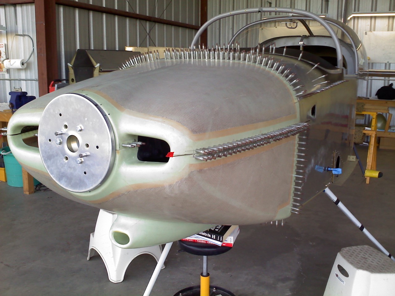
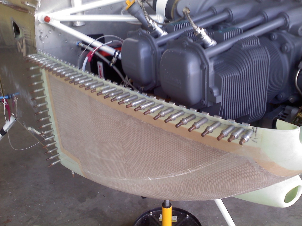
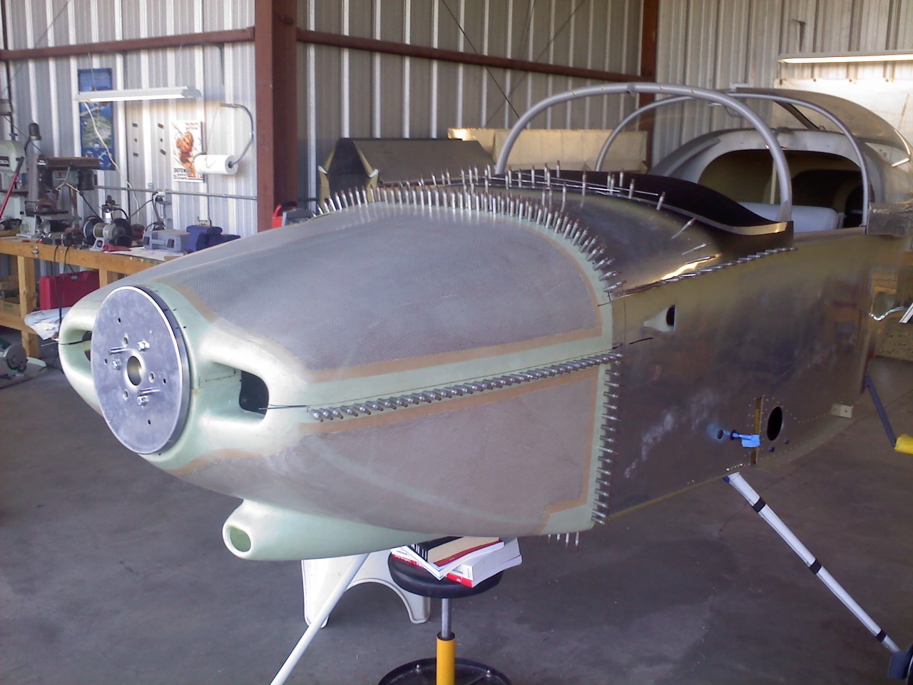
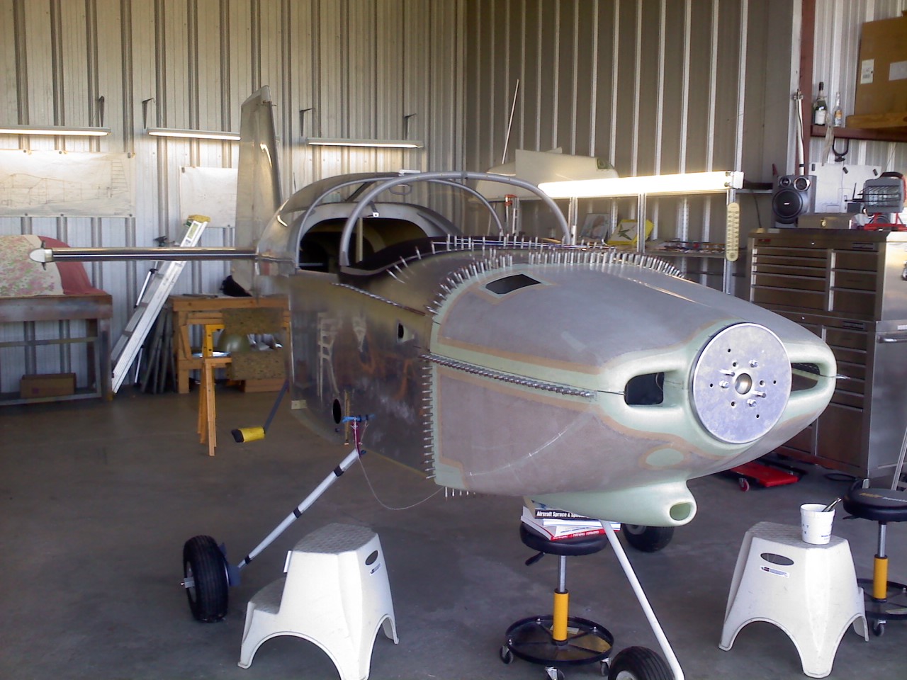
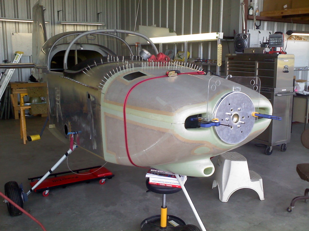
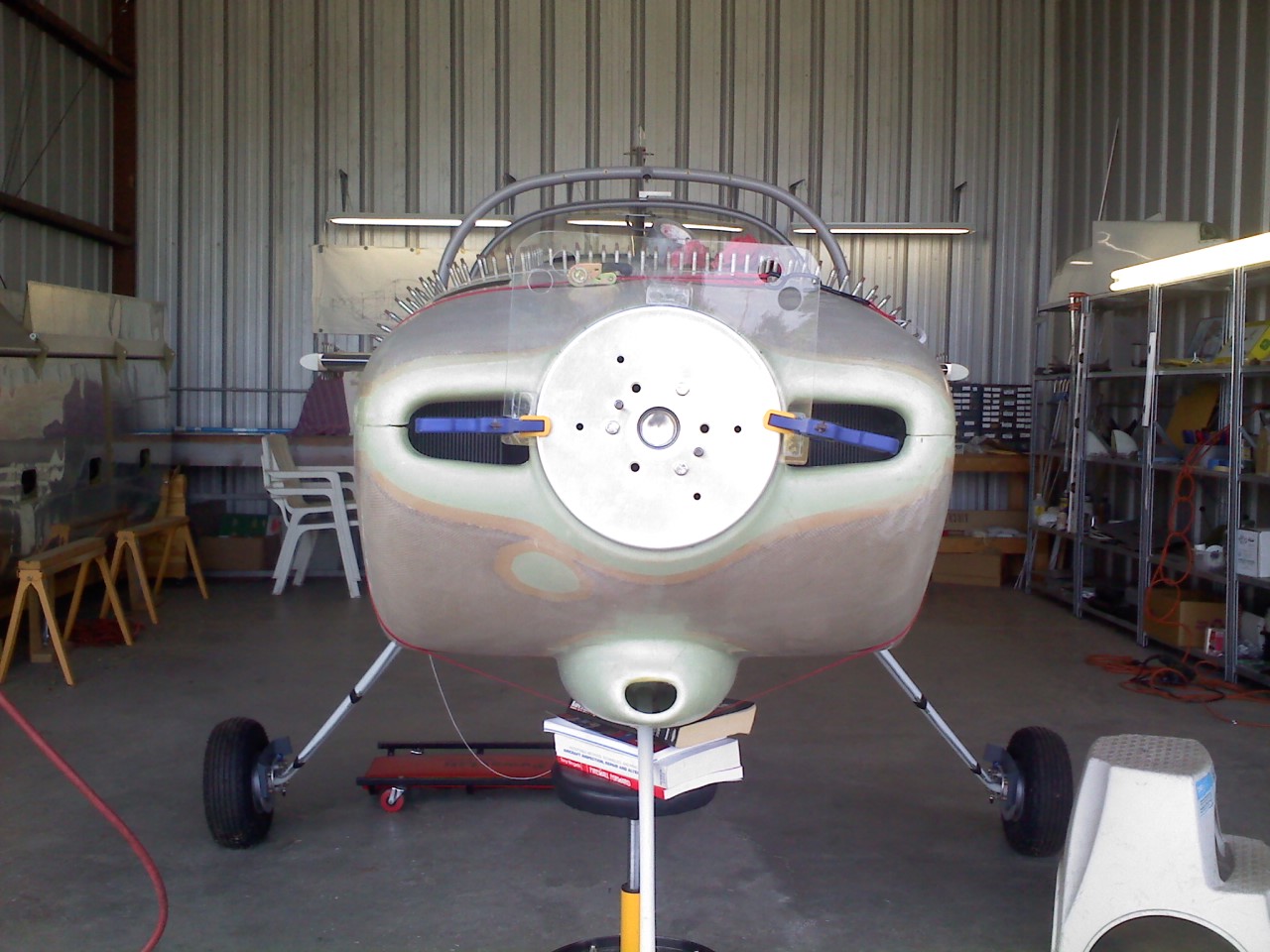
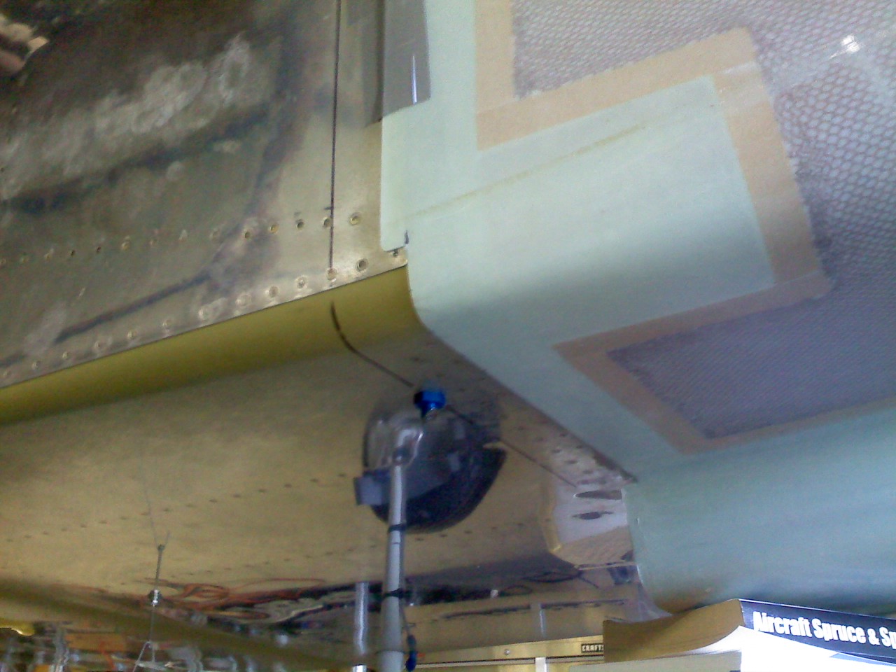
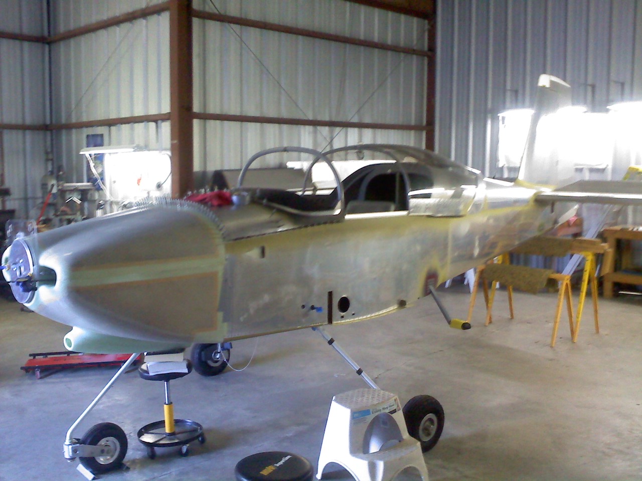
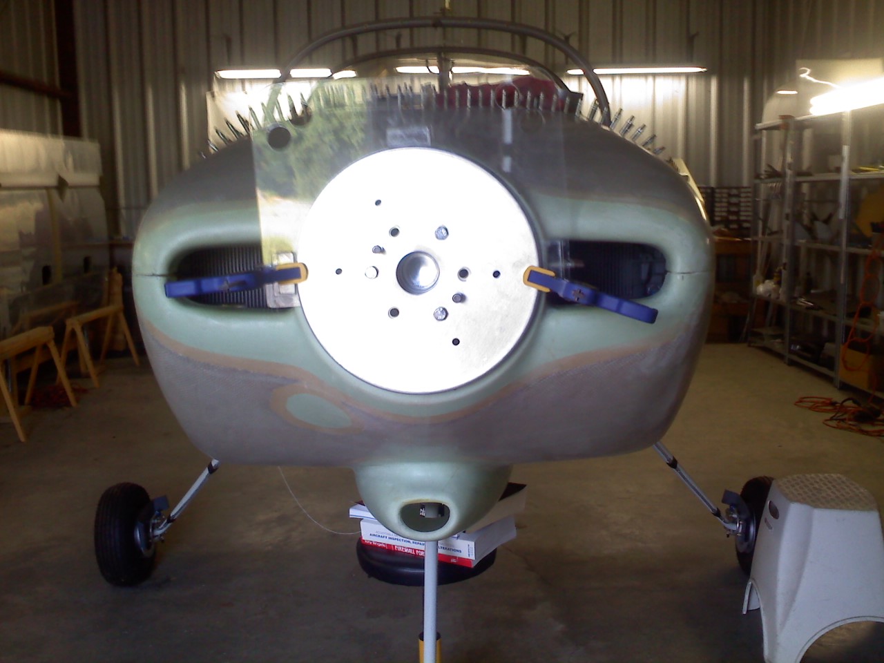
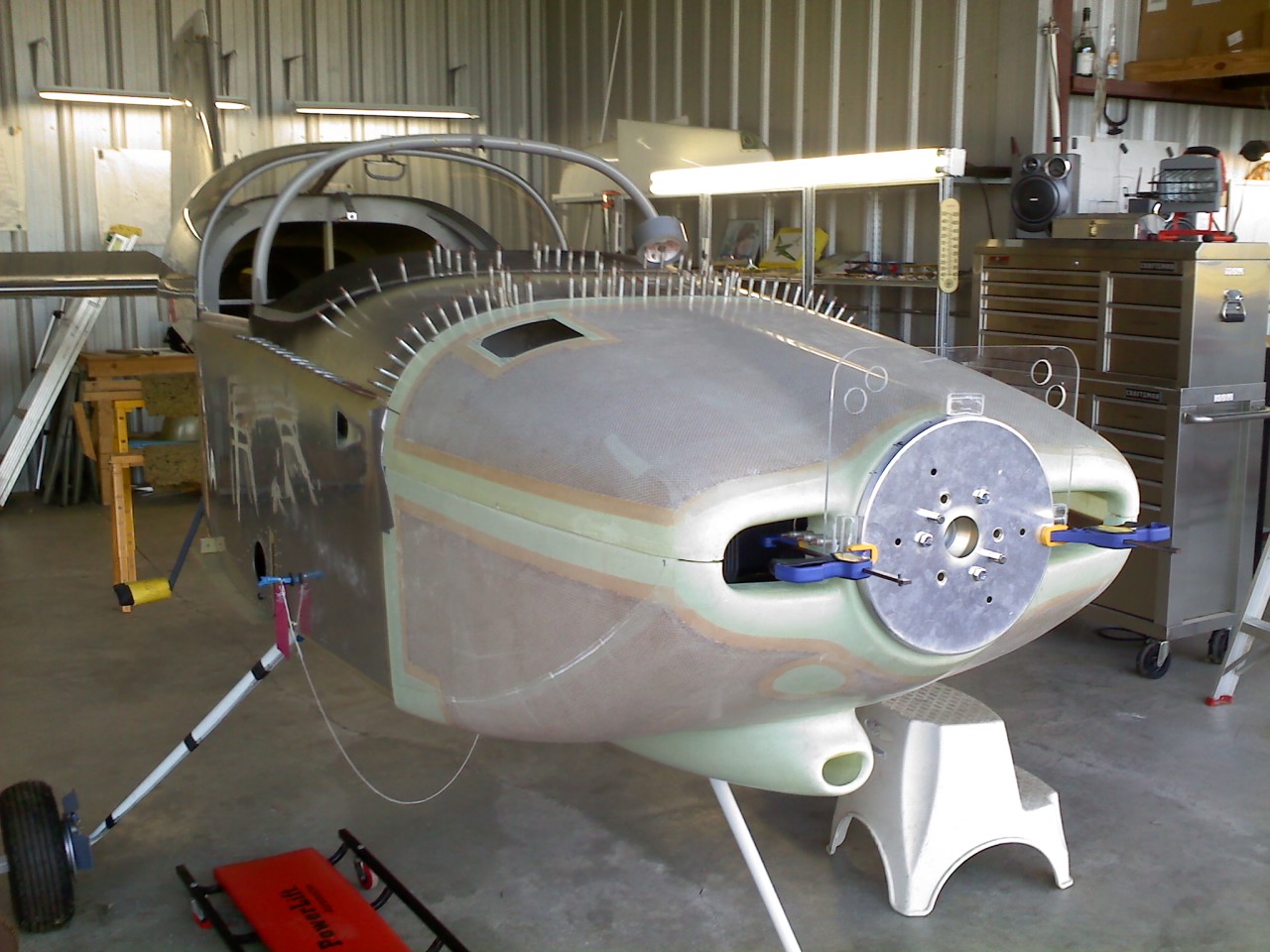
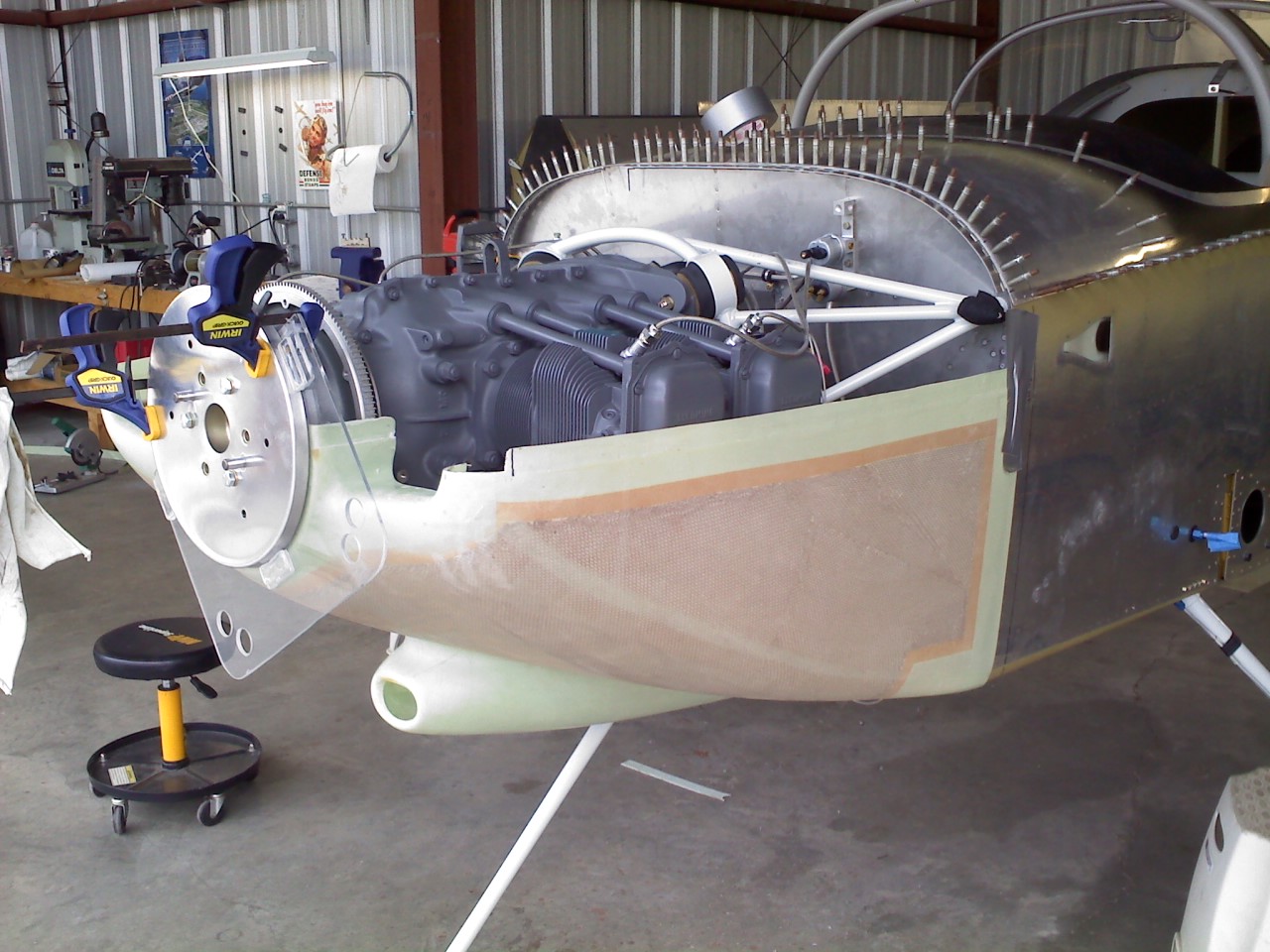
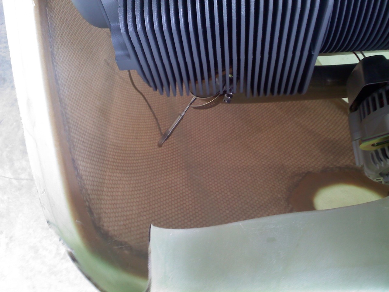
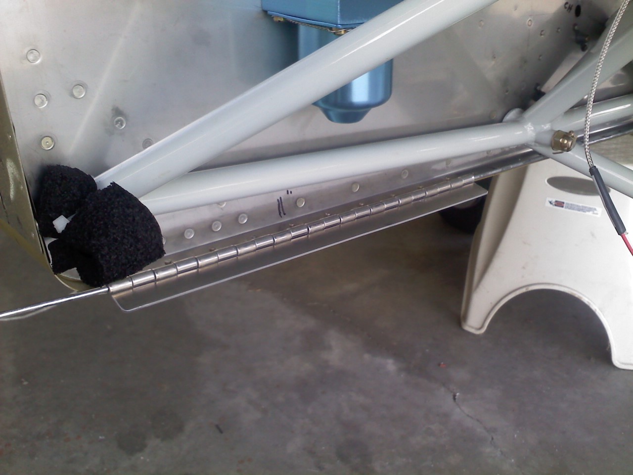
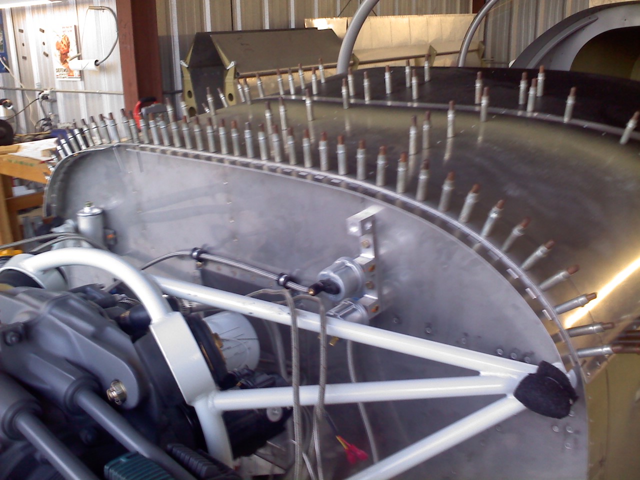
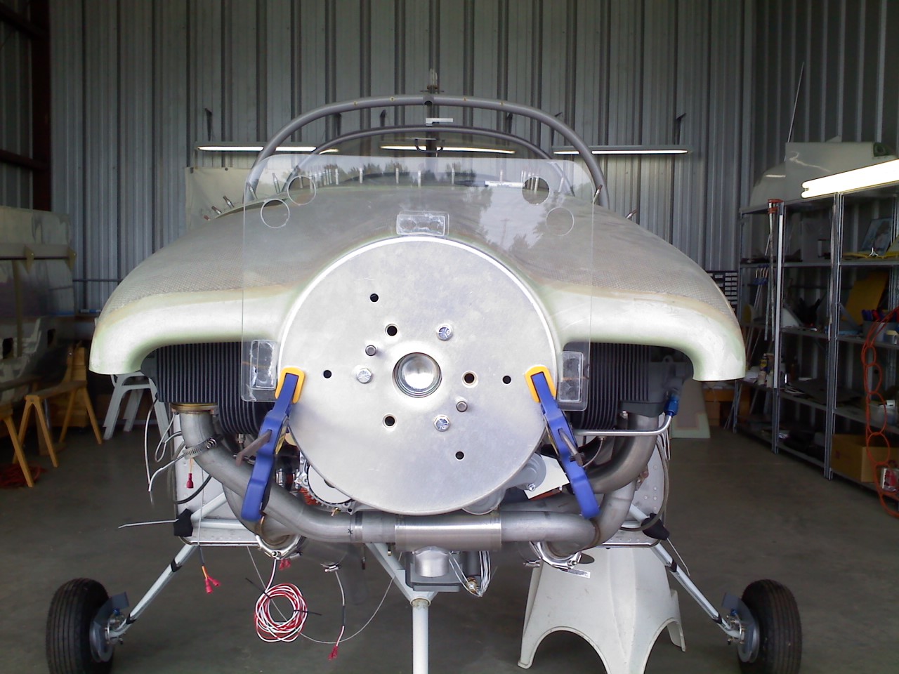
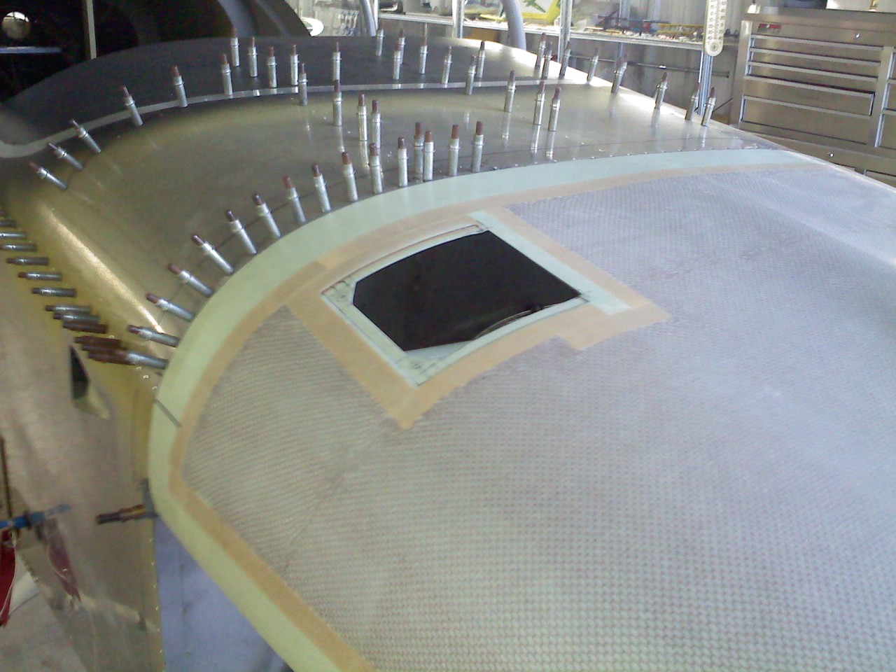
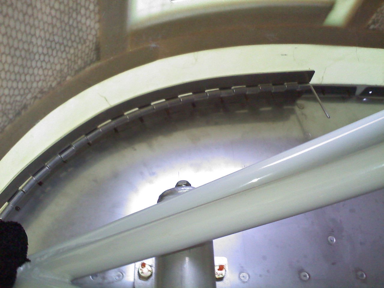
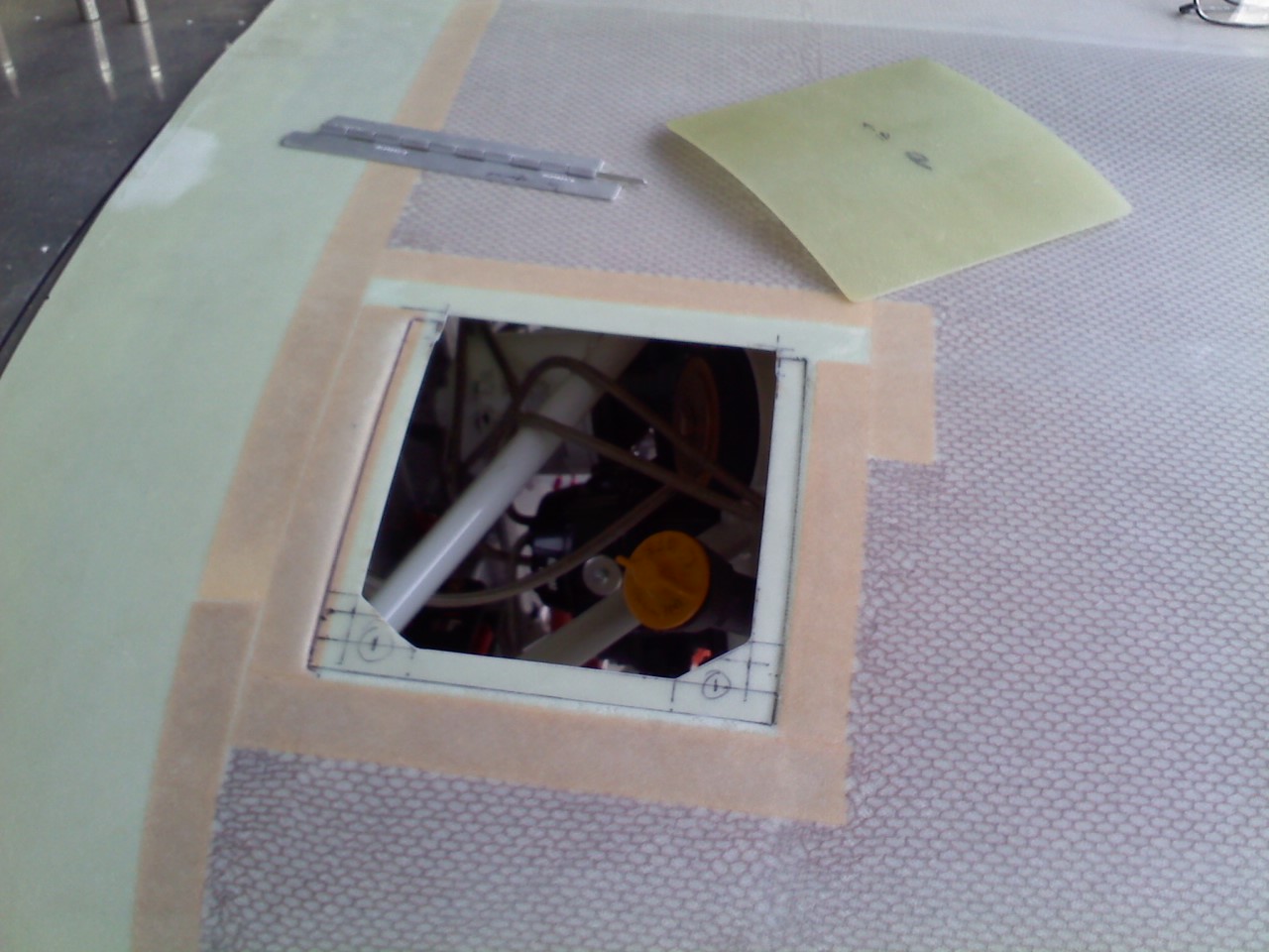
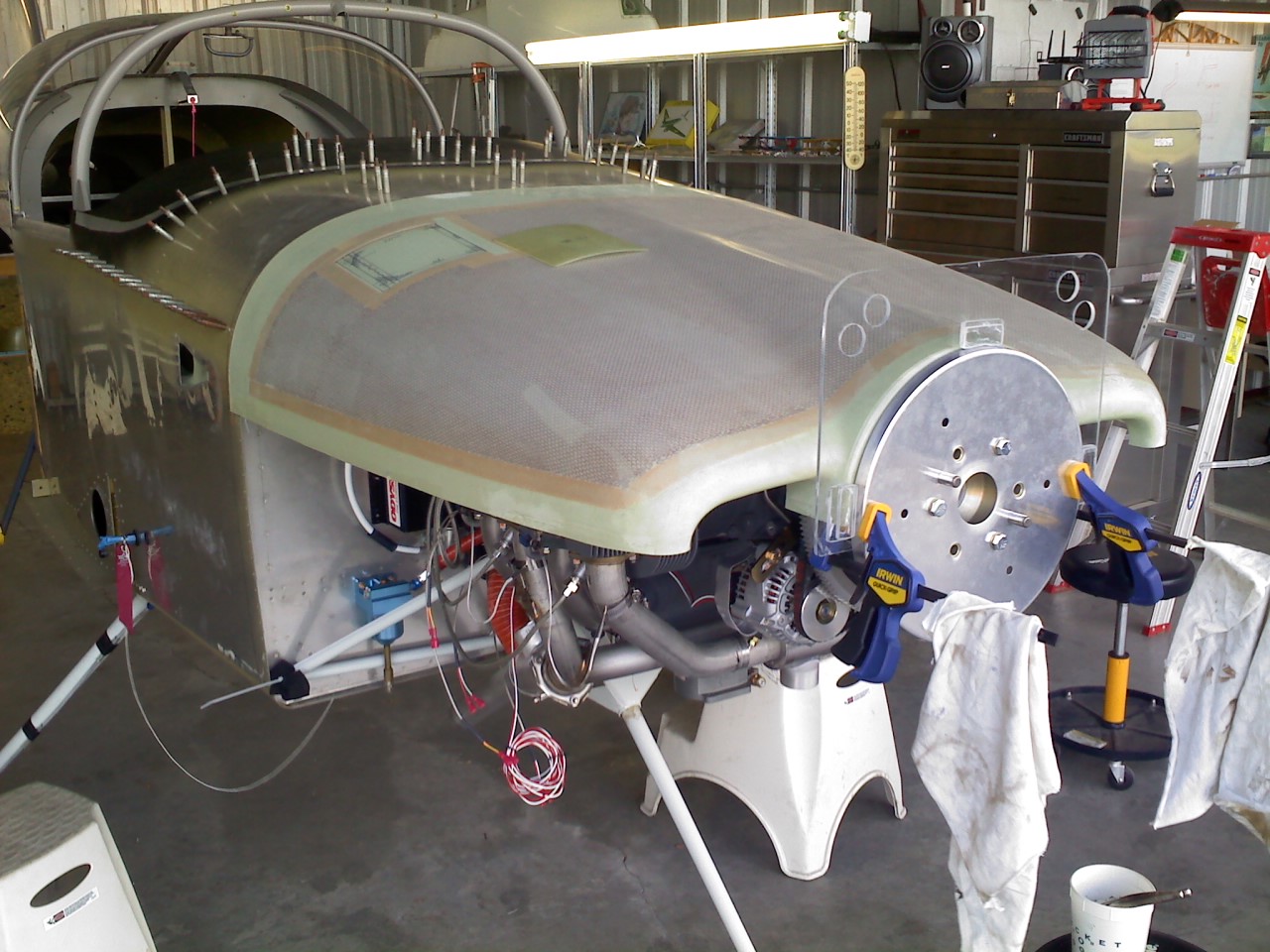
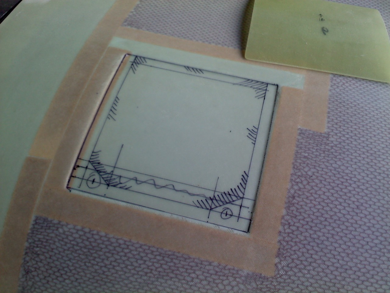
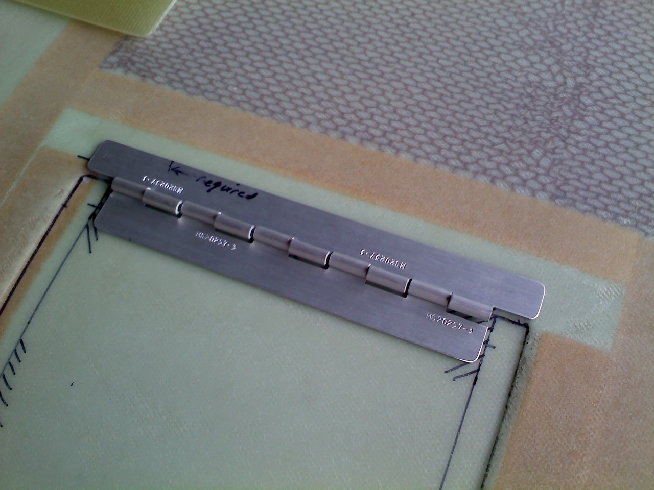
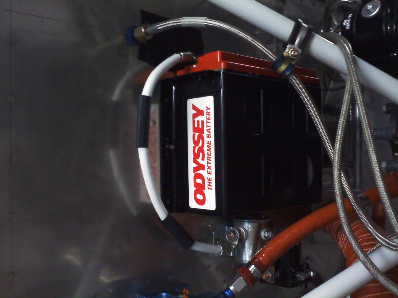
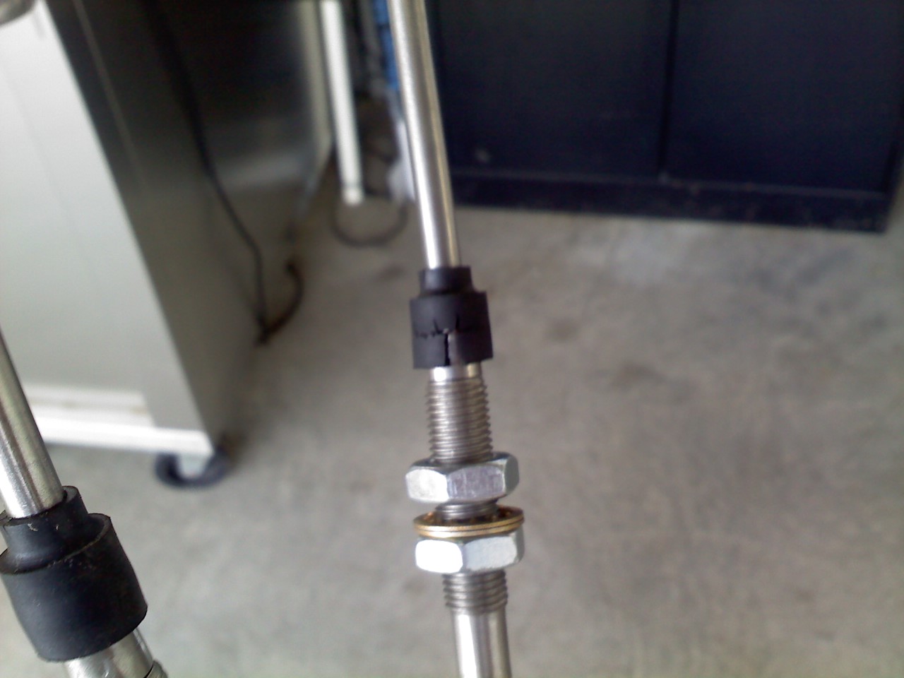
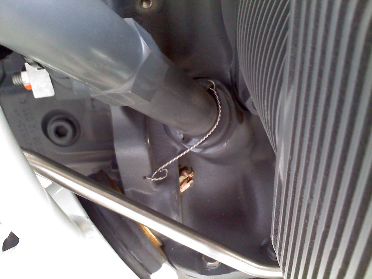
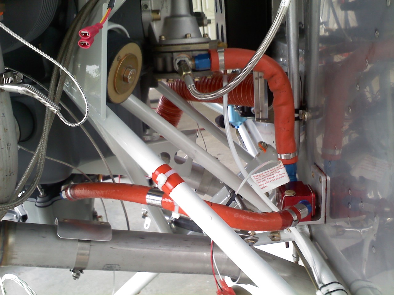
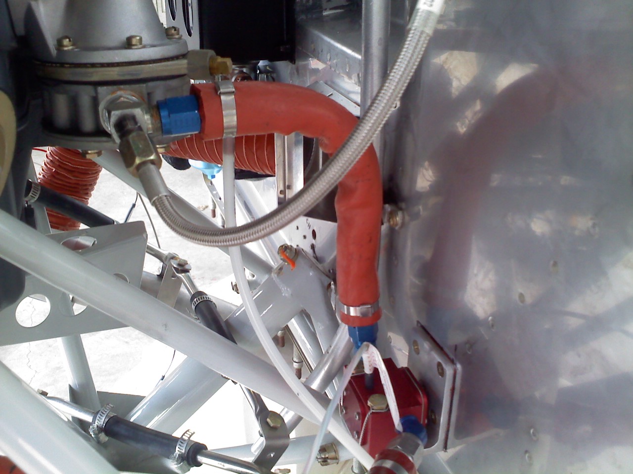
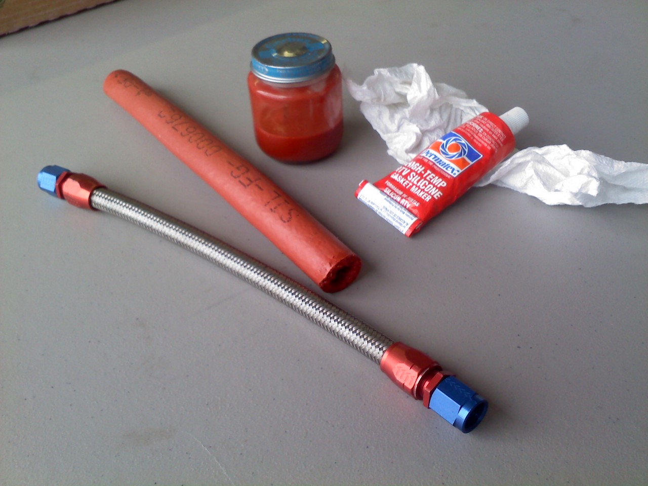
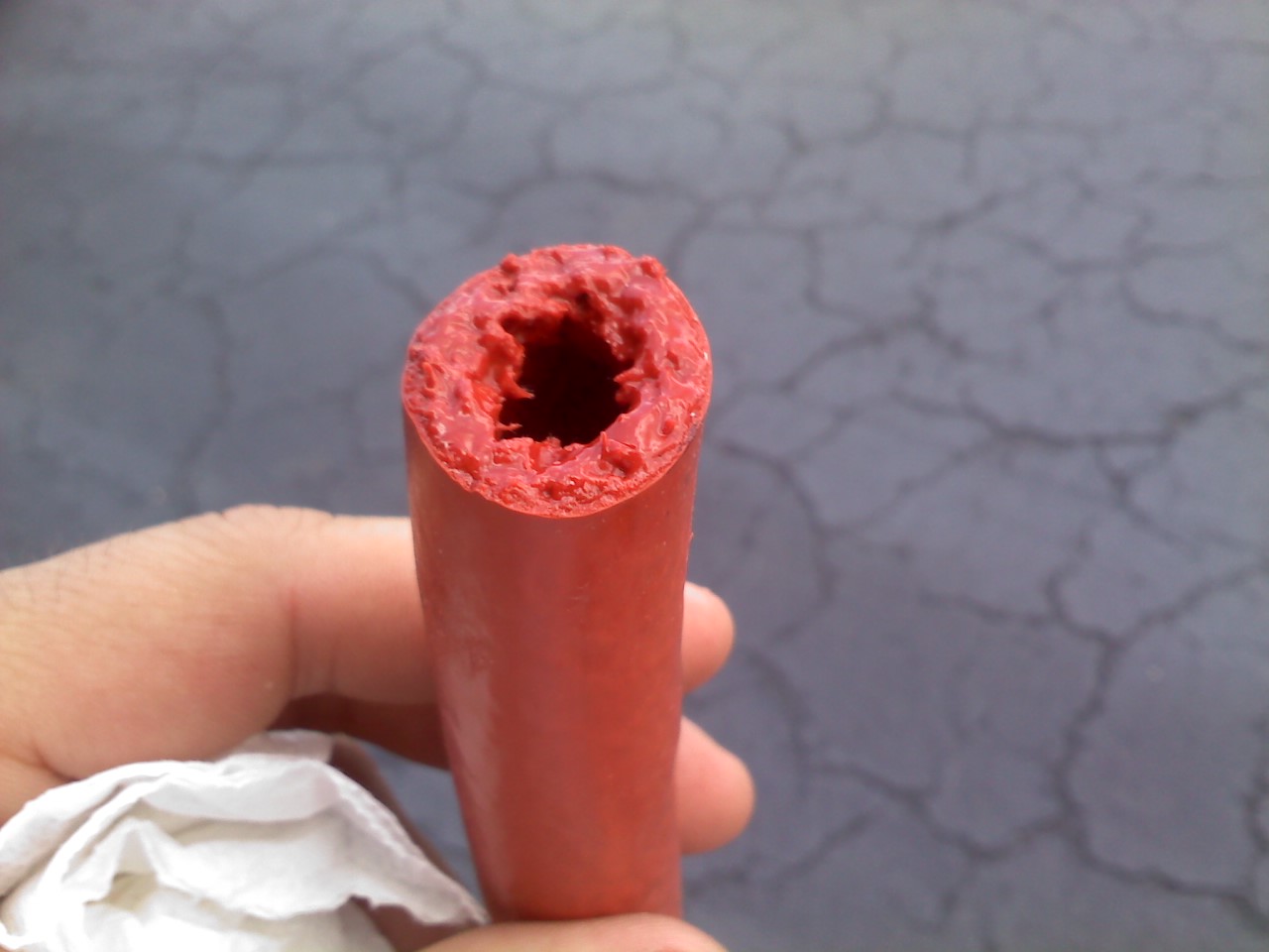
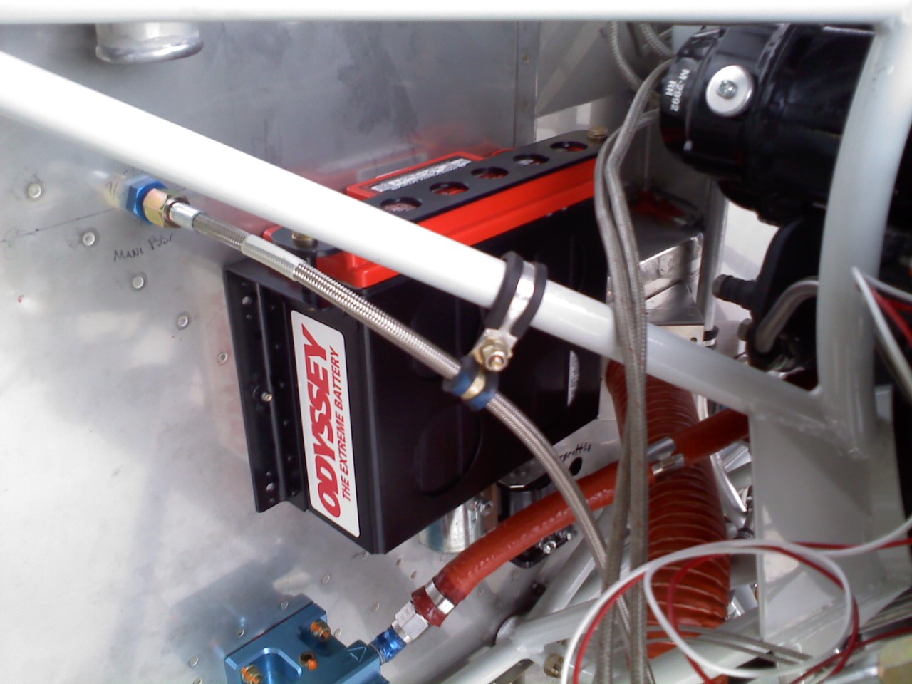
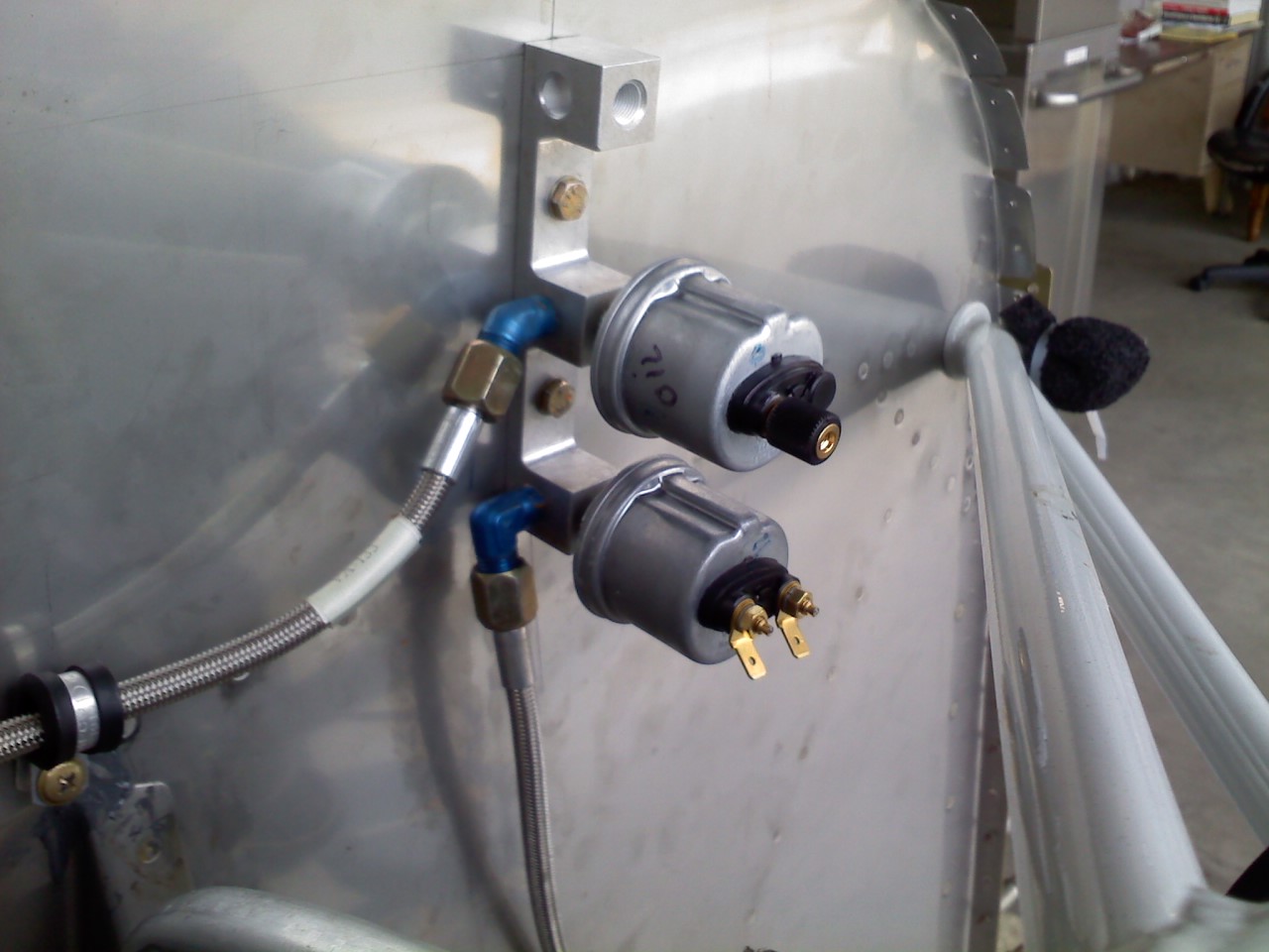
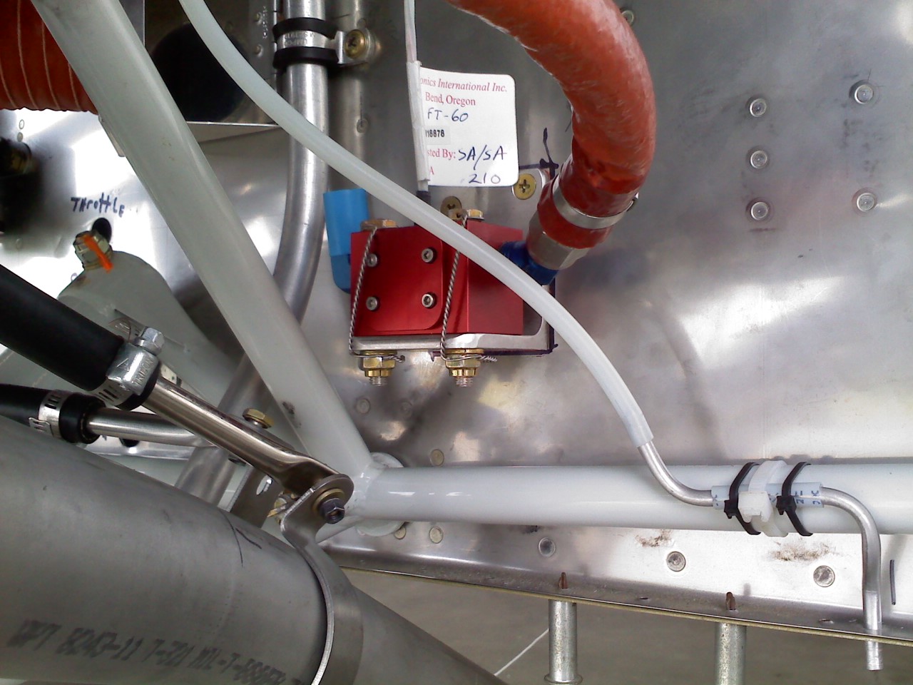
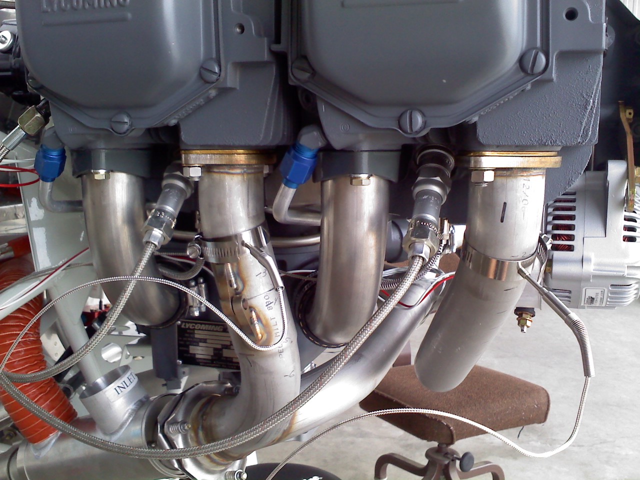
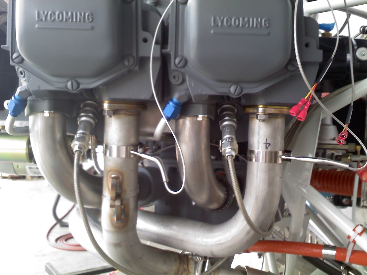
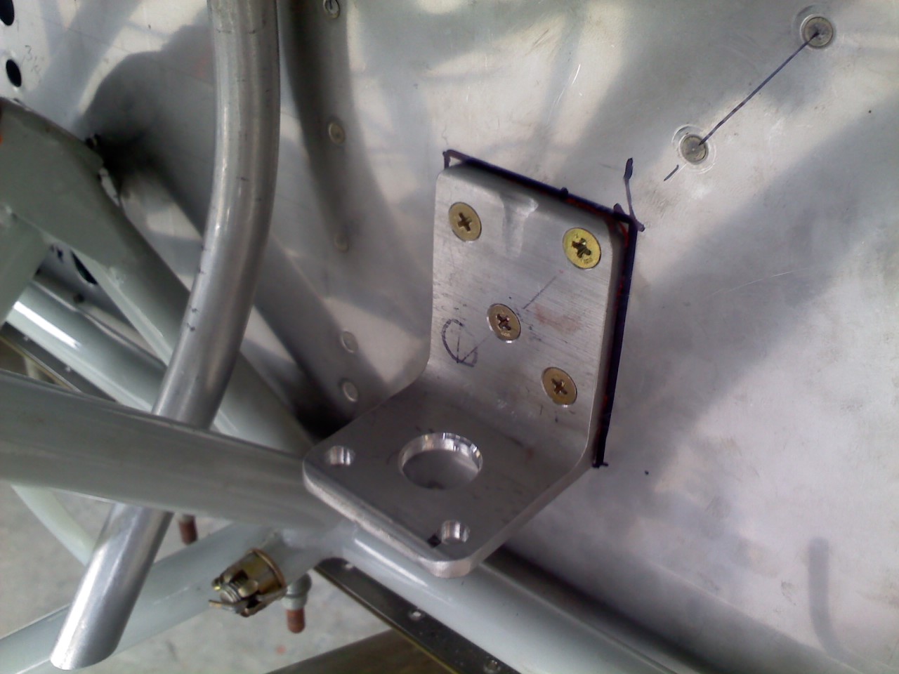
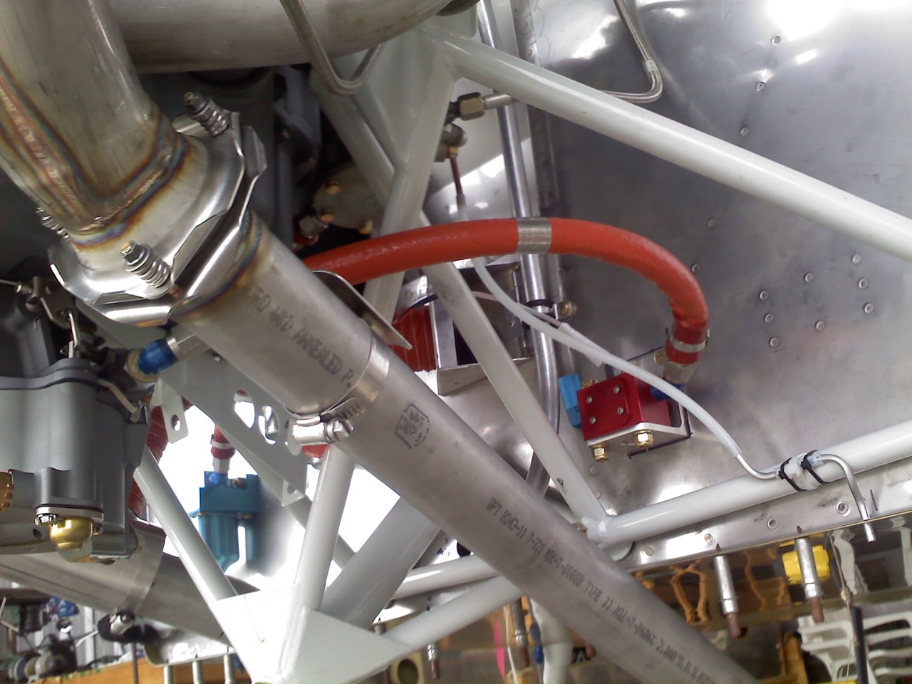
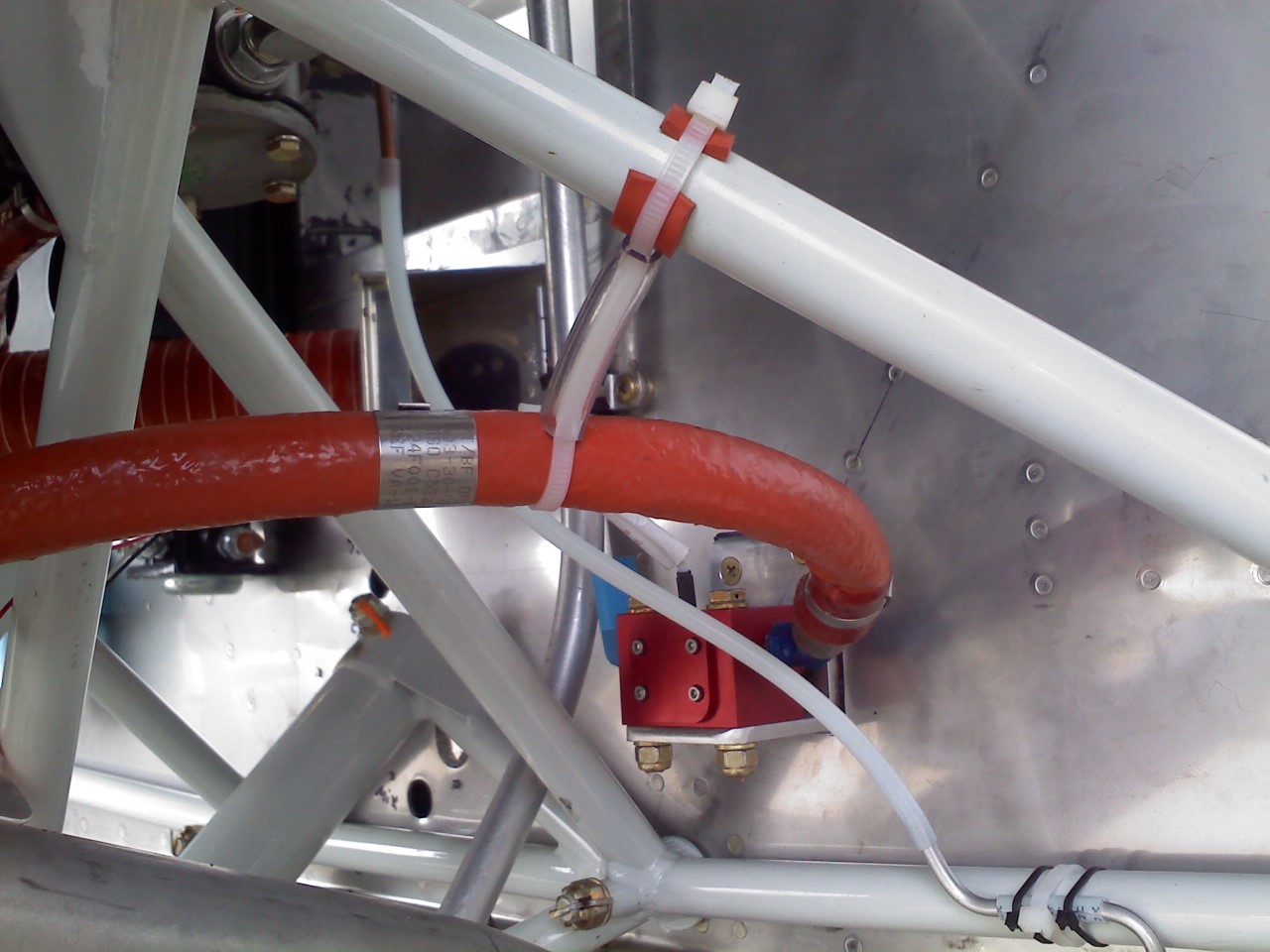
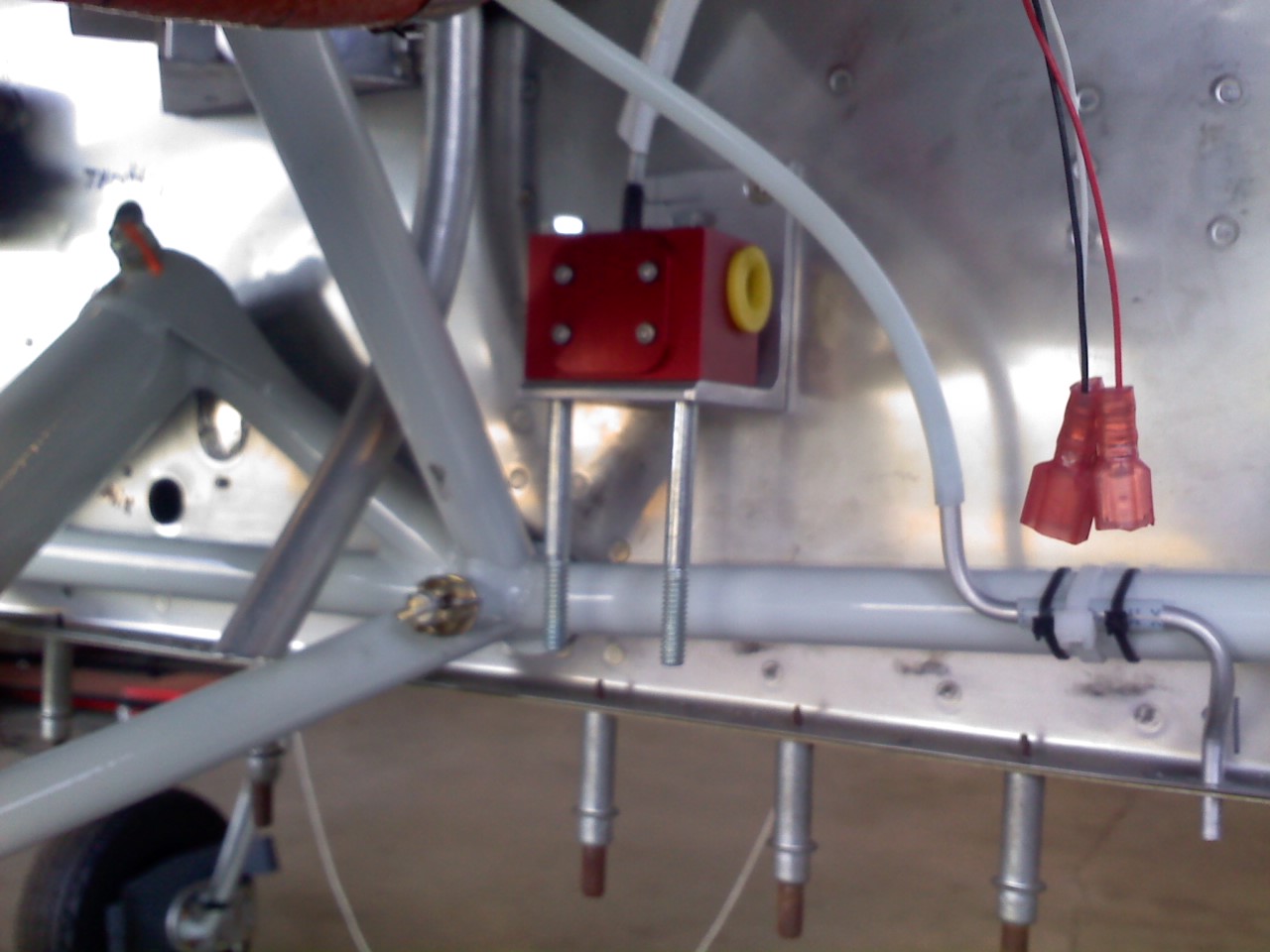
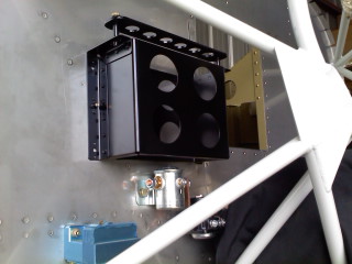
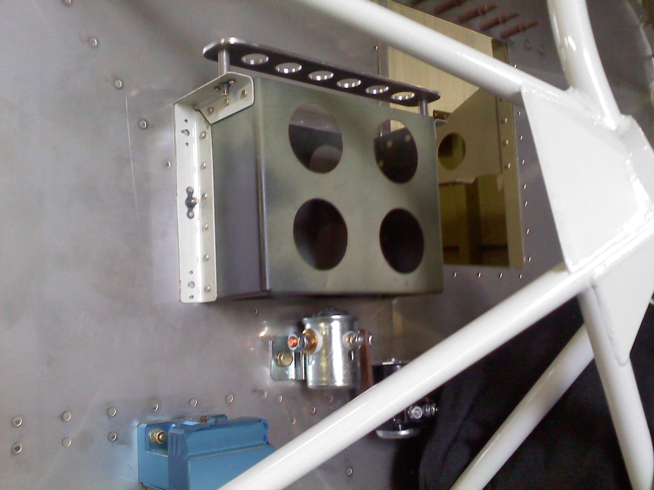
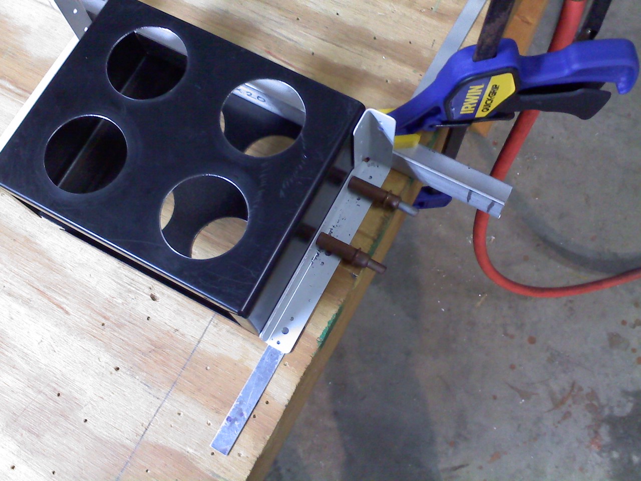
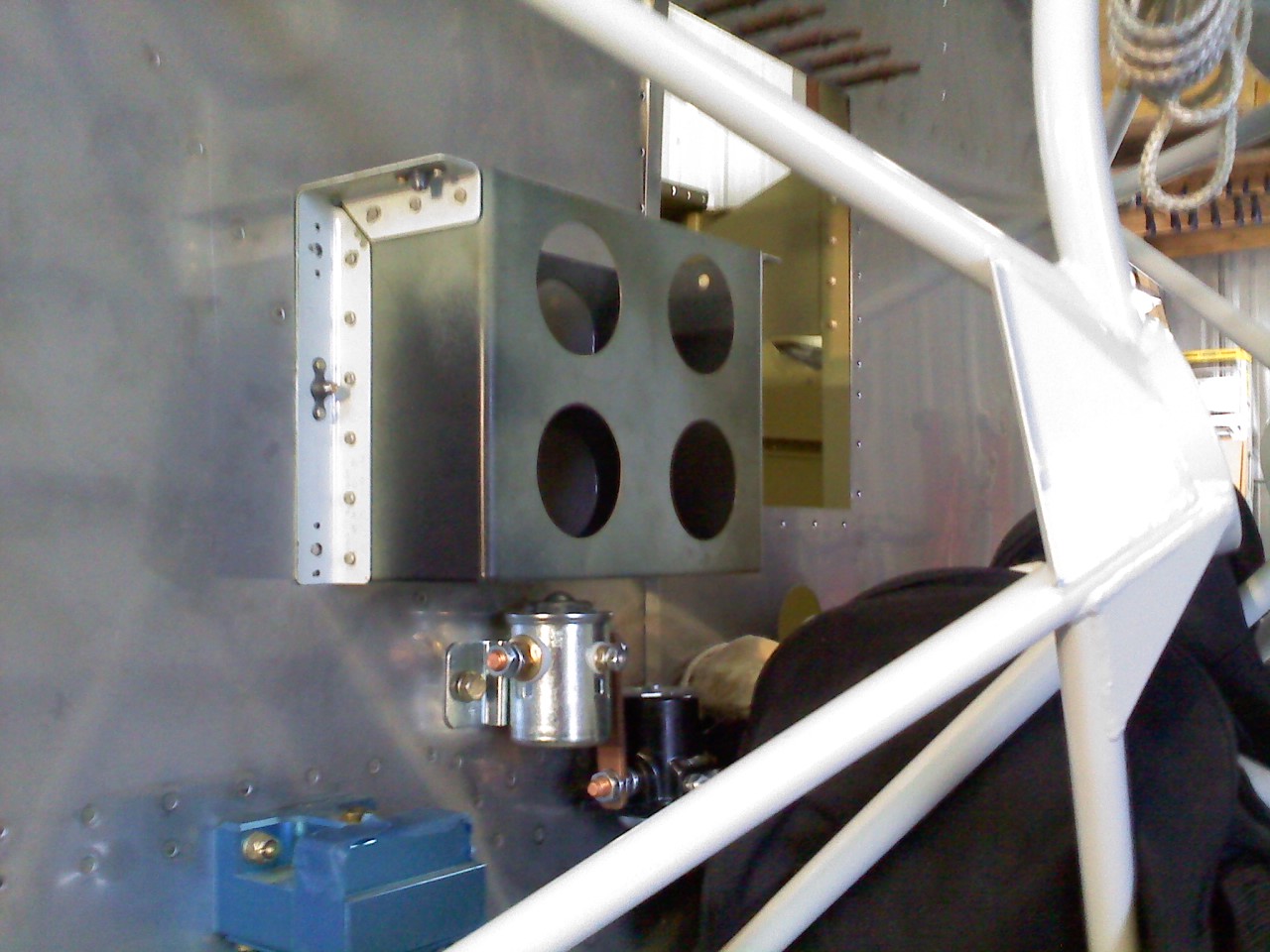
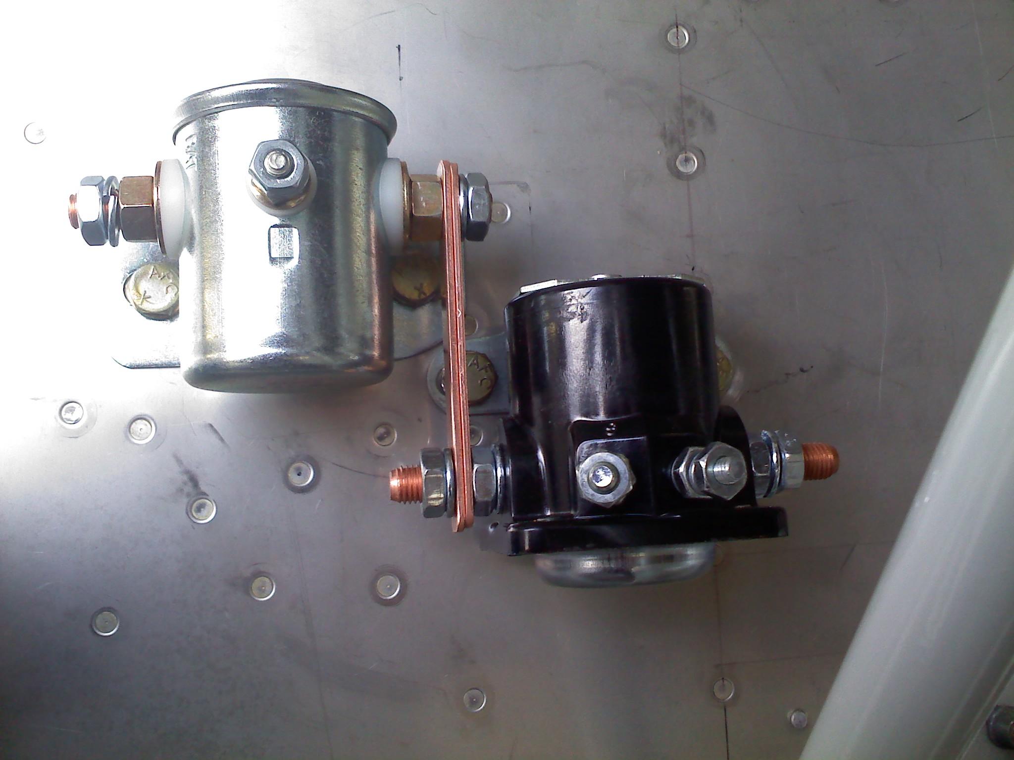
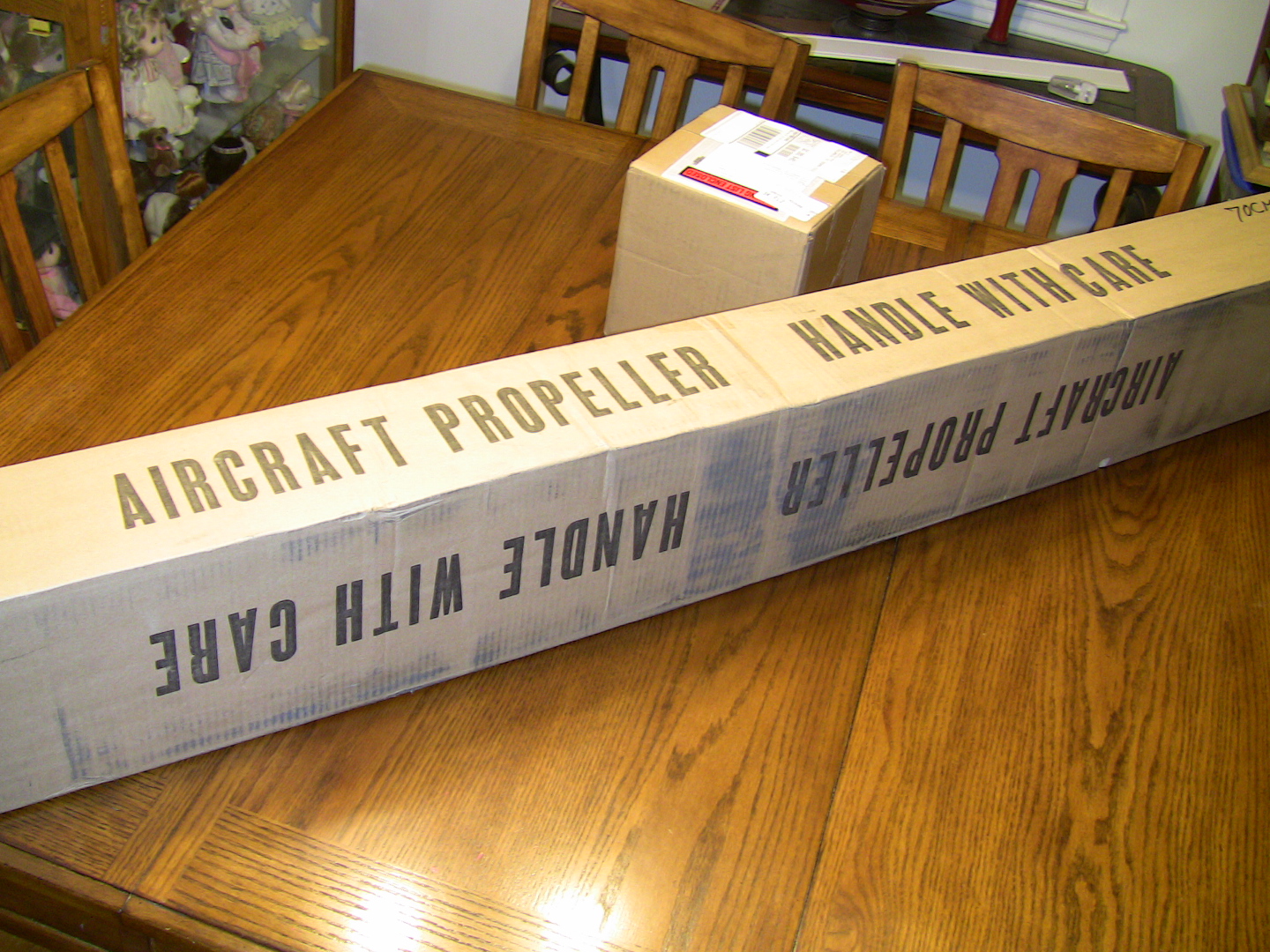
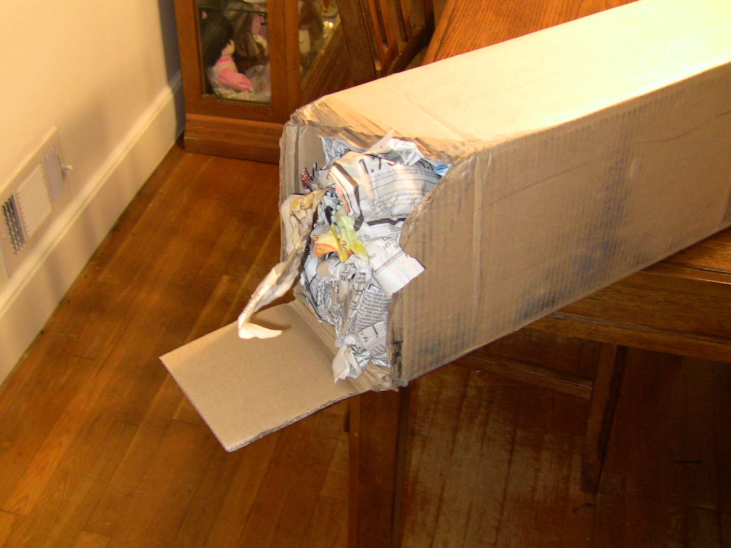