|
|
|
|
|
|
Official building time: 2224.3 hours.
|
|
|
Building time for Fuselage: 912.4 hours.
Number of records for Fuselage: 366. |
|
2010-06-18 |
Hours: 2 |
Category:
Fuselage
|
|
Manual Ref:
|
ID#:
1066
|
|
Finished fuel overflow, fitted alternator |
|
Finished working on the fuel overflow line. It will have to come out again in order to install the cowling hinges to the firewall flanges. I installed the alternator to see how it fits. Lots of head scratching about all the firewall forward stuff. Ordered the Dynon Skyview engine module with probe kit and fuel transducer.
|
|
|
2010-06-13 |
Hours: 3 |
Category:
Fuselage
|
|
Manual Ref:
|
ID#:
1065
|
|
I adjusted the fittings on the VA-168 sender mount. I had to remove it from the firewall to do so. The fittings were aligned so when the lines where connected, they where too close to the firewall. I angled them slight forward and reinstalled. I removed the FF-705 oil breather tube again and took a little bend out of the upper bend. This allows the tube to sit down further at the bottom end. I am sure more adjustments will be needed once the exhaust system is in place. I started work on the fuel pump overflow drain tube. This requires the aluminum tube to be bent in a complex way so that it can exit through a #12 hole in the firewall flange/hinge.
|
|
|
2010-06-12 |
Hours: 2.5 |
Category:
Fuselage
|
|
Manual Ref:
|
ID#:
1064
|
|
Worked some more on installing the fuel hoses. Decided to test fit the exhaust system. Oil from the exhaust ports was a mess to deal with. About 1/8 cup from each one as you remove the plastic seal. Bent the FF-705 oil breather tube. Actually, I unbent some of the curve in the upper bend. This added some height to the tube and removed some of the excess "forwardness" so that I could get the breather port and the tube to line up and then put more bend in - more of a ninety degree bend now.
|
|
|
2010-06-10 |
Hours: 2.5 |
Category:
Fuselage
|
|
Manual Ref:
|
ID#:
1063
|
|
I tightened the four engine bolts and installed the cotter pins. This was a little bit tricky. The bolt have to be turned a certain was to be able to insert the cotter pin. Began to installed the FF-705 breather tube, but this looks like it will be a big challenge left to another day. Not sure how this is supposed to go in so I will have to look at someone else's installation first.
|
|
|
2010-06-09 |
Hours: 2 |
Category:
Fuselage
|
|
Manual Ref:
|
ID#:
1062
|
|
There was not any good pictures or anything helpful to get the carburetor installed. I removed the plastic square piece that was bolted to the bottom of the sump where the carburetor goes. About a cup of oil drained out. I stuffed a rolled up paper towel in the hole for a couple of hours to soak up most of the dripping oil. I bolted the bracket and carburetor. The next morning there was some oil still dripping out of the carburetor
|
|
|
2010-06-08 |
Hours: 3.5 |
Category:
Fuselage
|
|
Manual Ref:
|
ID#:
1061
|
|
Got to the airport a little early today and opened the engine box finally! I cut the open the sheet plastic sealing the engine and marveled at the "Lycoming blue" engine. I installed the VA-128 restrictor fitting in the oil pressure port, and the two oil cooler line fittings in the engine block. Once again, Tom Roberts was kind enough to help me - this time to install the engine on the airplane. He apparently likes torture. It was a struggle, but finally the last bolt went in and there hung an O-320 on N194MH (reserved). This is a hallmark day - too cool! Thanks Tom once again for the help! It is much appreciated.
|
|
|
2010-06-07 |
Hours: 3 |
Category:
Fuselage
|
|
Manual Ref:
|
ID#:
1060
|
|
Installed the subpanel and ribs |
|
Riveted the subpanel and rib parts to fuse and firewall. Not as easy as I had thought it would be. I had to use several different bucking bars and several different configurations with the rivet gun: rivet set, double offset, and flush. Held the rivet gun in ways I had not before to get the job done. It's about time to mount the engine! Yeah!
|
|
|
2010-06-06 |
Hours: 2 |
Category:
Fuselage
|
|
Manual Ref:
|
ID#:
1059
|
|
Riveted the F-601K-1 firewall recess to the firewall |
|
I had forgotten how much fun working with Proseal is. I buttered up and riveted the overlaps in the F-601K-1 recess, then buttered up the firewall and cleceod the recess into place. Prosealled the corners of the recess to cover the holes and began riveting. This went pretty well even with the engine mount installed.
|
|
|
2010-06-05 |
Hours: 1.5 |
Category:
Fuselage
|
|
Manual Ref:
|
ID#:
1058
|
|
Made and installed plate to cover firewall nose gear hole |
|
Made a cover plate out of .032 aluminum to cover the oblong hole in the firewall at the nose gear bolt. Put a little proseal on it and riveted it to the firewall with aluminum rivets. The hole location on the drawing is slightly lower than what is required by about 1/2" if I remember correctly.
|
|
|
2010-06-03 |
Hours: 2.5 |
Category:
Fuselage
|
|
Manual Ref:
|
ID#:
1057
|
|
Main gear axle hub nuts finally drilled for cotter pins |
|
Tom Roberts again helped me get through a task I have put off for a long time. He showed me how he drilled the main gear axles for the hub nut cotter pin. Basically, we set the nut tightness by tightening it nice and snug, then backing off a couple of turns, the re-tightening until it it stops - not tight, just barely finger tight. Drilled the front and after holes with a 12" #30 drill. It was dull, so we just marked the hole locations with it. Removed the nut and drilled the holes completely through from the outside - we did not drill just from one side thru to the other side. Cleaned up the holes with a Dremel wire wheel and wiped to clean of metal flakes, put the nut back on and put the cotter pin in. Not sure which cotter pin Vans calls out. We could not find it anywhere. We used a -362. They are extra long. Thanks Tom for the help!
|
|
|
2010-05-29 |
Hours: 2 |
Category:
Fuselage
|
|
Manual Ref:
|
ID#:
1056
|
|
Finished the fuel lines and fittings inside the fuse |
|
Finished installing the fuel lines in the forward fuse. They were all in place, but I had waited to tighten and finish them in case I needed to removed them for any reason. I used Del seals on each flared fitting. Expensive little devils, but I think worth it for the fuel line fitting inside the fuse. Fuelubed and tightened all the fittings.
|
|
|
2010-05-27 |
Hours: 2.5 |
Category:
Fuselage
|
|
Manual Ref:
|
ID#:
1055
|
|
Drilled the hole and installed the fitting for the manifold pressure line in the firewall. installed the cotter pins in the engine mount bolts Installed the close tolerance bolt in the nose gear to engine mount and torqued it. It appears that I really need to acquire the engine monitors for the Dynon that I plan to use. I think there is a lot of that could be done easier as far as engine monitors before the engine is hung.
|
|
|
2010-05-26 |
Hours: 2.5 |
Category:
Fuselage
|
|
Manual Ref:
|
ID#:
1054
|
|
RTV'd a few firewall forward items and torqued the engine mount |
|
I removed the heater box from the firewall and put red RTV sealant on it per the manual and reinstalled. I had earlier put a bead of RTV around the brake reservoir firewall hole. I removed the gascolator and smeared a little RTV around the fitting hole and reinstalled. I realized that I had not yet safety wired the four screws in the bottom of the gascolator, so I bet I will have to remove it again to do that. After that I torqued the six engine mount bolts. The firewall forward instructions show only a half dozen or so more tasks before mounting the engine - this is getting exciting!
|
|
|
2010-05-25 |
Hours: 3 |
Category:
Fuselage
|
|
Manual Ref:
|
ID#:
1052
|
|
Added fluid to the brake lines |
|
Thanks to Tom Roberts for volunteering to help me add the brake fluid. I had never done this, but Tom has, so he knew what we were getting into AND STILL HELPED! Thanks a bunch Tom! The process went pretty well, but we did get brake fluid everywhere. I guess that is just part of it. There are still a few air pockets that we will get out of there soon, but the brakes operate nice and tight. Cold beer seems to help get rid of the brake fluid smell, so we tried that. ;)
|
|
|
2010-05-24 |
Hours: 3 |
Category:
Fuselage
|
|
Manual Ref:
|
ID#:
1053
|
|
Reinstalled the canopy slider hardware |
|
I reinstalled all the slider canopy components that I had removed from the fuse before I painted the fuse interior. I almost forgot what a devil the little washers and nuts are to put in under the canopy decks. Pam and her dad dropped by so we could show him the latest "progress" on the project, so we had to put the slider canopy back on the show him how it looks and operates. Okay, I really wanted to put it back on so I could sit in the cockpit and open and shut it a few times and work the now-operating rudder pedals and brakes.
|
|
|
2010-05-24 |
Hours: 1 |
Category:
Fuselage
|
|
Manual Ref:
|
ID#:
1051
|
|
Installed the VA-168 sender mount on the firewall |
|
I had earlier reinstalled the forward fuse structure and panel so that I could drill and install the VA-168 sender mount on the firewall.
|
|
|
2010-05-23 |
Hours: 4 |
Category:
Fuselage
|
|
Manual Ref:
|
ID#:
1050
|
|
Installed the brake lines |
|
I used Bakerseal on all the brake line fittings except on the flared portion of the fittings in installed them permanently (I think). I installed the two big black brakes lines from the firewall to the left side brakes. Ran lengths of the plastic tubing from the left side to the right side and from the right side to the fitting at the brake reservoir. This was an interesting task. At first I thought I could just measure the lengths of plastic line needed and install the brass nuts, sleeves and inserts on the bench. You can do one end like that but the other end needs to be done in place in the airplane as the line will not go through the snap bushing in the center rudder weldment brace. I had to use a heat gun the heat the end of the tube to get the brass inserts in all the way. One of the engine mount holes work well as a heat gun holder. After heating the end of the tube with the brass insert partially installed, I quickly shoved the heat gun into the nearest engine mount hole and pressed the end of the tube against a universal head rivet on the fuse to seat the brass insert all the way. Took two or three heatings each tube. Be careful not to over-heat - only a few seconds waving the tube end two inches from the heat gun should do - very warm, but not too hot as that might deform the tube.
|
|
|
2010-05-22 |
Hours: 2 |
Category:
Fuselage
|
|
Manual Ref:
|
ID#:
1049
|
|
Mulled over the drawings and instructions and test fitted all the brake fittings to see what goes where. Hope to install the brake lines tomorrow.
|
|
|
2010-05-21 |
Hours: 2 |
Category:
Fuselage
|
|
Manual Ref:
|
ID#:
1048
|
|
Installed the new SB'd trim cable anchor in the elevator |
|
Installed the trim cable thru the HS rib and into the elevator. Decided to go ahead and install Vans new service bulletin'd WD-415 trim cable anchor and got the trim working. There is about 1/4" play in the trim.
|
|
|
2010-05-17 |
Hours: 2.5 |
Category:
Fuselage
|
|
Manual Ref:
|
ID#:
1047
|
|
I drilled the holes in the rudder cable links, rounded the ends like on the drawing and cleaned and primed them. Also cleaned and primed the slider canopy rollers - I had not painted them yet. Also drilled the new WD-415 manual cable trim mount to the trim cable access plate and installed to see how it fit.
|
|
|
2010-05-15 |
Hours: 3 |
Category:
Fuselage
|
|
Manual Ref:
|
ID#:
1046
|
|
Work on rudder cable links |
|
Spent an abnormally large bit of time trying to get my rudder cable links sized up. after mounting the empennage and putting the rudder in neutral position, and lining up the left side rudder pedals, I found that the left side links need to be about 1/4 to 3/8 inches shorter than the right side links. Triple and quadruple checked and rechecked before I cut the steel links. I used .063 aluminum links to work with the get the lengths to where I want them. I cut the steel strip to the lengths required and marked for the holes.
|
|
|
2010-05-13 |
Hours: 3.5 |
Category:
Fuselage
|
|
Manual Ref:
|
ID#:
1045
|
|
Installed the empennage so I can install the rudder cables |
|
Decided to go ahead an install the empennage again so I can install the rudder cables and get the F-6119 rudder cable links cut to proper length. I will have to do some research to see how the install the cables before I cut these. Not sure of the correct procedure. I found that the passenger side pedals dictate the pedal extremes: the right pedal will hit the AN fitting on the top of the fuel pump and the left pedal will contact a firewall stiffener when pushed to the wall.
|
|
|
2010-05-12 |
Hours: 2 |
Category:
Fuselage
|
|
Manual Ref:
size=8
|
ID#:
1044
|
|
Installed nutplates on the firewall |
|
Installed three nutplates on the firewall stiffeners per plans. Two are at the top of the firewall recess. I had to drill and countersink before installing as the flush heads will be underneath the top flange of the F-601K-1 firewall recess. The other nutplate is to the left of the heater box and will be used to secure the vent tube. These locations are on the OP DWGs that come with the firewall forward kit. The plans and manual pages would be nice to have early on in the firewall construction. This would have been easier way back then.
|
|
|
2010-05-11 |
Hours: 1 |
Category:
Fuselage
|
|
Manual Ref:
|
ID#:
1043
|
|
Drilled some #12 holes in the firewall for adel clamps |
|
Trying to get as many firewall items done before hanging the engine. I hope to avoid having to remove the engine/mount. Drilled three holes around the recess area that will be used to secure pipes/lines with adel clamps. With the engine mount already on, I had to use my angle drill to drill these.
|
|
|
2010-05-04 |
Hours: 2.5 |
Category:
Fuselage
|
|
Manual Ref:
|
ID#:
1042
|
|
Installed the heater box on the firewall. At first this seemed like it would be a simple task, but this is an aircraft project. Locating and drilling the left side bolt hole was easy by mounting the heater box and back drilling thru the nutplate with a #30 drill, then step up to final #10 hole. I used a unibit to 3/16 to keep the hole round then finished with a #10 drill. The task gets difficult when you try to locate the right side hole. The nutplate is behind the heater box scat tube flange, so you cannot just back drill it. I took careful measurements of the distance between the centers of the holes on the aft side of the heater box, measured carefully on the firewall and drilled a #40 pilot hole. Installed the heater box with the one left side bolt to see how well I did. By moving the heater box up and down to see the nutplate countersunk rivets pass by the #40 hole in the FW, you can tell how well the pilot hole was located. Mine was pretty much dead on, so I removed the heater box and finished drilling the right side hole to a #10. Drilled the hole in the right side firewall stiffener 1/4" lower than was called out on the plans due to the battery box bolt head interfering. Finished drilling to a #10 hole for the cabin heat control cable to pass thru. Bent the end of the control cable per plans and installed it to test it out. This cable is pretty long; I am sure it will have to be cut short once I have the location of the control on the instrument panel. I will wait until I think I do not have to remove the heater box again before I finish install it with the red high temp RTV sealant.
|
|
|
2010-05-03 |
Hours: 1 |
Category:
Fuselage
|
|
Manual Ref:
|
ID#:
1041
|
|
NOW I'm back to where I thought I was - missed something from long ago |
|
I decided to put a length of shrink tube over the threaded rod that secures the slider canopy slide rail at the baggage bulkhead. With the threaded rod in place, I measured the distance between the two jam nuts. This is the length of shrink tube I will need. I removed the rod and put the shrink tube on it and re-installed it. Looks nice and hopefully the thing will not rust up again. I went to test fit the F-652 upper baggage bulkhead when I realized that it will not go on - I had not notched it to clear the threaded rod and jam nut. This notch is called out on DWG 29, SECTION A-A. This is the only reference. All drawings show the F-652 upper baggage bulkhead without the notch - as would be the case for the tip up canopy. I guess I missed this a few years back when I was working with the baggage bulkheads. So, I installed the F-652 upper baggage bulkhead without the slider threaded rod installed and marked the hole location from the aft side, thru the hole already in the F-706A fuselage bulkhead. Removed the F-652 upper baggage bulkhead and drilled a hole to 9/16" with a unibit and then trimmed material from their to the upper edge of the F-652 upper baggage bulkhead. Deburred and smoothed the edges and then reinstalled to test the fit with the slider rail threaded rod installed. Done!
|
|
|
2010-05-03 |
Hours: 2.5 |
Category:
Fuselage
|
|
Manual Ref:
|
ID#:
1040
|
|
Fuel lines done (redone) - Now I'm back to where I thought I was |
|
Got the fuel lines hooked up to the Andair fuel valve. I elected to use unions on either side of the valve instead of trying to run new lines thru the gear weldments. I used a small hack saw to cut the lines between the F-982B and F-983B support ribs. I left extra length on the outboard portion to give me some wiggle room to adjust to proper length and be able to more easily flare the ends. I had to bend the tube with the spring bender forward to get at it with the flare tool. First I made the inboard lengths of line that connect to the Andair fuel valve and go down and outboard thru the F-983B support rib. I used enough tube to make sure I had extra length on the outboard end to cut away as needed to meet up with the outboard line/union. I cut the outboard lines, installed nut and sleeve, the flared the end and attached the union. I pretty much just eyeballed were to cut the inboard line to match up to the union. Once I had it cut, I put on the nut/sleeve and flared the end. This was much easier as I was able to pull this little length thru the hole in the F-983B support rib to a position that I needed to flare the end. Once flared, I reconnected to the Andair fuel valve and the union to the outboard length of line. The inboard lengths are easy to duplicate: start with about 9 or 10 inches of tube; the end that attaches to the Andair fuel valve down to the 90 degree turn is 3" to the outside of the radius. From there 4" more from outside radius to outside radius of a 45 degree bend. Need at least 3" minimum from there outboard to work with thru the F-983B support rib and have enough to move the nut and sleeve out of the way of the flaring tool.
|
|
|
2010-04-27 |
Hours: 2.5 |
Category:
Fuselage
|
|
Manual Ref:
|
ID#:
1039
|
|
Began to reinstall fuel lines to the Andair fuel valve |
|
Today I began reinstalling fuel lines to my new Andair fuel selector valve. I made a new line to go from the valve to the fuel pump, then began work on the left and right fuel lines. I hope I will be able to salvage the existing lines that go through the gear weldments. I cut the existing lines between the F-982B and F-983B cover support ribs and removed the length of fuel line that goes from there to the old Vans standard valve. I took some measurements and rebuilt the lines from the cut points to the new Andair valve. So, I will need to get two unions to connect the lines on each left and right fuel line. I had hoped to avoid this, but I don't want to pull new lines through the gear weldments.
|
|
|
2010-04-16 |
Hours: 4 |
Category:
Fuselage
|
|
Manual Ref:
|
ID#:
1038
|
|
Reinstalled some items in the fuselage |
|
Sure spent a lot of time doing what seems like very little. I installed the grip handles into the roll bar and reinstalled the roll bar onto the fuse. I had forgotten what a booger this was. Took a lot longer than I expected. I also reinstalled the fuel vent lines in the forward fuse. I cleaned and removed the rust from the threaded rod that holds the slider canopy rail secure and then spray painted it to keep it from rusting again. Installed it.
|
|
|
2010-04-14 |
Hours: 2 |
Category:
Fuselage
|
|
Manual Ref:
|
ID#:
1037
|
|
I think I'm finished painting for a while |
|
Today I painted the roll bar and roll bar brace and touched up some spots inside the fuse. Only have a few drops of paint left - maybe enough for touching up later. Glad this is done!
|
|
|
2010-04-13 |
Hours: 6 |
Category:
Fuselage
|
|
Manual Ref:
|
ID#:
1036
|
|
Painted the fuselage interior and more |
|
Painted the fuselage interior and the dashboard area of the top forward skin. I used flat black on the dash. The interior is painted with JetFlex water-based. I am real happy working with the JetFlex. It sprays on nicely and sets quickly and seems to be very durable. We'll see. And clean up is easier with the water-based paint. Also, there is no mixing of components initially, just added 10 percent water.
|
|
|
2010-04-12 |
Hours: 2 |
Category:
Fuselage
|
|
Manual Ref:
|
ID#:
1035
|
|
Getting closer to painting the interior, I primed a few more parts: roll bar and roll bar brace, top skin in the dashboard area ready for flat black paint, and the pilot side control stick.
|
|
|
2010-03-31 |
Hours: 3.5 |
Category:
Fuselage
|
|
Manual Ref:
|
ID#:
1034
|
|
Painted interior panels, seat backs, etc. |
|
Finally a beautiful not so windy day to do some painting. I set out to get the interior of the fuse painted but only got all of the removable panels, seat backs, etc. painted.
|
|
|
2009-09-28 |
Hours: 2 |
Category:
Fuselage
|
|
Manual Ref:
|
ID#:
1025
|
|
Getting ready to paint the interior |
|
Removed the slider canopy and stored it. Removed the roller rail, slider pin block, panel, roll bar and forward top skin. Getting it ready to clean and paint inside.
|
|
|
2009-09-24 |
Hours: 5 |
Category:
Fuselage
|
|
Manual Ref:
|
ID#:
1024
|
|
Grip handles installed in roll bar |
|
Saw some nice looking grip handles in an RV at Oshkosh and decided to install some like them. Ordered some round bar from ACS and fabricated two of them after practicing on a scrap piece. The stuff is hard to bend. Drilling them into the roll bar takes some studying. You need to make sure the slider canopy front bow does not scrap them when you open and shut it. After priming and painting, I think they came out pretty nice.
|
|
|
2009-09-19 |
Hours: 2.5 |
Category:
Fuselage
|
|
Manual Ref:
|
ID#:
1023
|
|
Finished assembling the slider canopy |
|
Finished pop riveting the canopy today. I popped the fore and aft bows, and squeezed all of the C-660 side to C-666 aft skirt rivets. Then I squeezed the rivets on the dog house. Installed the rear handle on the top. The slider canopy is done!
|
|
|
2009-09-18 |
Hours: 5 |
Category:
Fuselage
|
|
Manual Ref:
|
ID#:
1022
|
|
Began final assembly of the slider canopy |
|
Began assembling the slider canopy. I reinstalled the slider pin blocks. Then I put the canopy frame on the fuse, installed the rear slider rail block bolt and roller bolts and clecoed the canopy to the frame. I got inside and riveted the C-791 braces to the canopy frame. Next I riveted the C-660 side skirts to the canopy frame. Installed the screws in the lower side canopy to side skirts. Riveted the lower flanges of the C-791 braces to the side skirts. Then I installed the C-666 aft skirts. It was getting late but I couldn't help but install a few pop rivets. I popped the dorsal rivets and a few on the top of the fore and aft bows and called it a night.
|
|
|
2009-09-16 |
Hours: 2 |
Category:
Fuselage
|
|
Manual Ref:
|
ID#:
1021
|
|
Painted the slider canopy frame and parts |
|
Finally got my Jetflex interior paint in. Looks to be a pretty darn good match to my leather swatches from ClassicAero. I have the Ash color interior with Light Grey inlaid. The Light Grey is actually the darker color. I painted the slider canopy frame, side skirts, aft skirts, side braces, dog house and fuel valve plate. Cannot wait to start assembling the slider canopy for good.
|
|
|
2009-09-08 |
Hours: 1 |
Category:
Fuselage
|
|
Manual Ref:
|
ID#:
1020
|
|
While I am waiting for my interior paint to arrive, I decided to tackle modifying the F-983A fuel valve mount plate to accept my new Andair fuel valve. The valve looks very well made. The Allen valve that Rutan "recommends" from ACS as a drop in replacement was not a drop in replacement for the standard valve Vans sells. I figured that if I need to rework my fuel lines, I might as well install the Andair. It was only $50 more than the Allen valve and is much much nicer. The switch indicator plate and anodized selector knob are quite nice. The valve came with a packet of screws and a couple of allen wrenches. One allen wrench to remove the selector knob and the other to install the eight screws - four for each fuel fitting outlet from the valve. The fuel fittings are installed on the fuel valve housing but the screws have not been inserted. So I inserted the screws until tight. I will have to redo my fuel lines. I may just cut them half way between the gear weldments and the fuel valve and install union fittings instead of pulling completely new fuel lines from the wing root. I had already sized, flared and fitted the fuel lines to the wing tanks fittings a good while back. I was able to salvage the F-983A fuel valve plate by locating the required 1" hole such that I would avoid having its three screw mount holes coincide with the two existing bolt holes for the old valve. And it is still centered on the fuel valve plate. The Andair will be a much nicer valve operationally and aesthetically.
|
|
|
2009-09-03 |
Hours: 2 |
Category:
Fuselage
|
|
Manual Ref:
|
ID#:
1016
|
|
I had to modify the dog house to get it to fit correctly without (hopefully) causing the aft skirts to lift once they are riveted together. I looks like I have everything ready to disassemble and prepare for painting. I am waiting on my paint to arrive.
|
|
|
2009-08-31 |
Hours: 5 |
Category:
Fuselage
|
|
Manual Ref:
|
ID#:
1015
|
|
Right side C-660 side and C-666 aft canopy skirts |
|
Got the right side C-666 aft canopy skirt fitted to the slider/fuse. This side was a bit higher in the back than the left side, so I had to put more bend in the top part of the aft skirt to get it close to lying down on the top aft fuse skin. Also had to put some bend in the bottom of the side skirt to get a closer fit. Lucky I had Tom Roberts come by. He helped by get this aft skin drilled and clecoed. Thanks Tom!
|
|
|
2009-08-30 |
Hours: 4.5 |
Category:
Fuselage
|
|
Manual Ref:
|
ID#:
1014
|
|
Wrestling the left side C-666 aft skirt and C-660 side skirt |
|
More grueling slider canopy work today. Third day of the skirts marathon. I had to remove them, modify them, put them back on a bunch of times. I finally got the fit of the C-666 left aft canopy skirt to fit okay. There is a gap at the bottom of the side skirt where the two over lap, but I believe I will call this side done. Whew!
|
|
|
2009-08-29 |
Hours: 4 |
Category:
Fuselage
|
|
Manual Ref:
|
ID#:
1013
|
|
More canopy slider aft skirt work |
|
Long day in the hangar again today, trying to get the left side C-666 aft canopy skirt to fit. Had to work the metal a good bit and still cannot get it to look good. Also, the aft end of the C-660 side skirt needs to be bent inward to lie flat against the fuse skit. It juts out at the last few inches and is causing the aft skirt at the overlap to stand away from the fuse. I have put on and taken of the aft skirt and side skirt over a dozen times, bending where I think it needs bending. Tiring chore when you cannot see the end getting near.
|
|
|
2009-08-28 |
Hours: 3 |
Category:
Fuselage
|
|
Manual Ref:
|
ID#:
1012
|
|
Began working on the slider canopy aft skirts. Got the left side C-666 aft canopy skirt drilled and clecoed to the aft canopy bow. It wants to stick out at the bottom where it intersects the C-660 canopy side skirt. Also, the side skirt needs to be bent inward below the rivet line of the C-791 brace to remove the gap between the side skirt and the fuse skin. Not sure how this is going to turn out. I know why the aft skirt was called C-666 now - it's the devil to get it to fit correctly.
|
|
|
2009-08-26 |
Hours: 2 |
Category:
Fuselage
|
|
Manual Ref:
9-14
|
ID#:
1011
|
|
Installed slider canopy aft handle |
|
Installed a handle on the aft dorsal of the slider canopy to make it easier to open. Started by drilling the two screw holes through the top to #40 all the way through the dorsal bar. Removed the canopy, enlarged the two holes to 7/32", deburred and sanded all the canopy edges with fine sand paper to finish them nice and smooth. I think I am done drilling and sanding the canopy. Next i enlarged the two handle holes in the canopy slider frame, stepping to #30, 21 then 19. Same with the aluminum strip. Clecoed the canopy back onto the slider frame, installed the C-660 side skirts with #6 screws and clecoes, and then test-fitted the handle. Looks like it will work very well.
|
|
|
2009-08-24 |
Hours: 2.5 |
Category:
Fuselage
|
|
Manual Ref:
9-14
|
ID#:
1010
|
|
Deburring, dimpling and countersinking the C-660 slider canopy side skirts |
|
Took a lot of time to do very little visibly. Got the C-660 slider canopy side skirts deburred, dimpled and countersunk were appropriate and re-clecoed them to the slider canopy. I installed the #6 screws. Need to get to the aft skirts. Oh boy! Also, I am installing a cabinet handle on the aft dorsal of the slider canopy to make it easy to open the canopy from the outside. Also contemplating installing some handles into the roll bar to assist getting in and out of the cockpit.
|
|
|
2009-08-22 |
Hours: 1.5 |
Category:
Fuselage
|
Helper: Pam
|
Manual Ref:
9-14
|
ID#:
1009
|
|
Drilled and clecoed the slider canopy side skirts to C-791 braces |
|
I trimmed more off of the C-660 side skirts at the forward bottom edge to allow more clearance from the canopy deck. It now is a bit over 1/16" and does not scrape the caonpy deck when it is opened. Drilled and clecoed the C-660 slider canopy side skirts to the C-791 braces. Pam held the side skirts tight on the outside with a piece of wood and I drilled from inside. Pam clecoed as we went along. Once done, there is a small gap in the C-660 overhang. Perhaps I can roll the bottoms of the C-660's a little to get them to seal tighter.
|
|
|
2009-08-21 |
Hours: 2.5 |
Category:
Fuselage
|
|
Manual Ref:
9-14
|
ID#:
1008
|
|
Drilled and clecoed the slider canopy side skirts to the the canopy |
|
Drilled and clecoed the C-660 slider canopy side skirts thru the canopy lower edges and the C-759 inside skirts. This went pretty well, but I had to de-cleco every few that I drilled to clean out the shavings where it was building up between the side skirts and the canopy. This was to make sure the side skirt lay up against the canopy tightly before moving onto the next holes (started drilling from the middle, fore and aft.) After that task, I was going to drill the C-791 skirt braces but I had to remove the material from the forward lower edges of the C-660 side skirts per the plans in order to open the canopy. I measured the overlap of the side skirts to the fuse side at the forward end of the skirts and used this measurement at the 8 15/16" mark. After cutting the material away, and filing some, the side skirts fit with just a little bit of clearance when the canopy is shut. But then I open the slider canopy, the forward lower corners of the side skirts contact the canopy decks so more material will need to be removed.
|
|
|
2009-08-20 |
Hours: 2.75 |
Category:
Fuselage
|
|
Manual Ref:
9-14
|
ID#:
1006
|
|
Drilled and clocoed the C-660 and C-759 to the slider canopy side rails |
|
After plenty of head scratching, measuring and more measureing, I marked the top two rows of rivets on the C-660 side skirt and drilled to #40. Next I marked the center line on the slider frame side rails and then match drilled the C-660 side skirts to the slider frame side rails. Then more head scratching trying to figure out how to get the C-759 inside canopy skirts positioned correctly to get a starter hole drilled. I didn't see any dimensions for positioning the C-759 fore or aft; the manual only says to line up the top edges of the C-660 with the C-759 and drill four holes spread evenly along the length of the C-660. This is so you can cleco both the C-660 and C-759 to the slider frame side rails so you can finish drilling and clecoing all the holes. So I put extended marks on the fore-most hole in the slider frame side rail vertically and horizontally, place the C-759 by itself into position and drew a crosshair based on the extended lines. See photo below. Once this was done I clecoed both the C-660 and C-759 to the slider frame side rails and drilled the remaining holes. Next - drilling the canopy lower edge screw holes.
|
|
|
2009-08-18 |
Hours: 3 |
Category:
Fuselage
|
|
Manual Ref:
9-14
|
ID#:
1005
|
|
Installed the aft slider rail on the top aft fuse. I had some unused positioning holes that needed to be filled with rivets to nowhere in the fuse skin. Also a few in the slider rail itself. Drilled and countersunk the screw holes and installed on the fuse. Drilled the C-791 skin braces to #30 to the inside of the canopy side rails. Had to sit inside with the canopy shut to do this.Uh...you can't open the canopy with those clecoes in! Removed them and decided to pre-drill the rivet holes in the bottom flange of the C-791's, versus pre-drilling the C-660 side skirts and hoping they line up well when match drilling the C-791 skirt braces as the manual proposes. I will match drill from inside for that row of rivets.
|
|
|
2009-08-16 |
Hours: 1 |
Category:
Fuselage
|
|
Manual Ref:
9-14
|
ID#:
1004
|
|
More work on the slider canopy latch assembly |
|
I did not get the top handle installed very well. Can't seem to drill a straight hole today. I enlarged the screw hole in the top canopy latch handle to a #10 because my #8 hole was crooked. Turns out that my first handle will work out better than the one I just bought. Oh well! I had to use an AN3-7A bolt for now. I will order a screw from ACS. At least the handle is centered nicely when the canopy is locked shut.
|
|
|
2009-08-15 |
Hours: 1.5 |
Category:
Fuselage
|
|
Manual Ref:
9-14
|
ID#:
1003
|
|
Slider canopy latch mechanism |
|
Got my new parts for the slider canopy latch mechanism. I wasn't happy with the way the first iteration turned out. I got the latch arm working very well. It locks tightly but not too tightly. Not happy with the way the top handle turned out.
|
|
|
2009-08-12 |
Hours: 2 |
Category:
Fuselage
|
|
Manual Ref:
9-14
|
ID#:
1002
|
|
C-665 anchor blocks and C-677 rear pin mounts |
|
I decided to try and rig up a jig on my drill press. It is an 8" Delta. I remembered that the drill press platform can be tilted at an angle, so I loosened the bolt and rotated the platform to about 23 degrees as called out on the DWG 41, C-677 Rear Pin Mount view. After moving the drill up and down on the press and making minor adjustments, I got the press lined up with the marks on the C-665 anchor blocks. Now for the other angle, approximately 5 degrees inward, I used a piece of 1/16" aluminum angle clamped to the drill press platform and sat the edge of the anchor block on the edge of the aluminum angle and noted where it sat when the angle was close to the 5 degree mark. I clamped another piece of angle perpendicular to the first one to act as a stop for the anchor block so it would not slip. Then I held the anchor block as steadily as I could and drilled the 1/4" hole. I test-fitted the anchor block in the C-677 rear pin mount and worked the slider canopy several times to check the fit. It is tight and snug but the angle seems right, so I reversed the drill press platform and re-did the jig for the other anchor block and drilled that one too. I test fitted both anchor blocks and worked the slider back and forth. It was too tight, so I decided to drill out the holes with a 17/64th drill to about 1/2" deep into the anchor block holes. This allowed the canopy pins to enter and exit nicely. So I drilled and countersunk the C-677 rear pin mounts for the AN509-10R18 screws and installed them. Seems to work pretty well. I had to make some adjustments to the anchor blocks, removing material off the forward edges (approx. 1/16") with a small chop saw. This allowed the slider canopy to shut completely with the anchor pins driven all the way home.
|
|
|
2009-08-11 |
Hours: 2.5 |
Category:
Fuselage
|
|
Manual Ref:
9-14
|
ID#:
1001
|
|
Slider canopy latch and rear pin anchor work |
|
Worked more on the slider canopy latch assembly to try and get it to work better. It is too loose. I reordered parts just in case I need to redo this. I bent a double joggle in the latch arm to make it catch the pin more reliably. It also made the latch shut tighter due to the joggle taking a slight bit of length out of the latch arm. Still not completely happy with this. More later. I installed the C-677 rear pin mounts. I marked lines on the C-665 rear pin anchor blocks according to the manual and drilled the spot hole where the pins contact the blocks. I have a drill press but no drill press vice, so I thought it best to stop for the day before trying to drill the pin holes manually with no jig.
|
|
|
2009-08-10 |
Hours: 3 |
Category:
Fuselage
|
|
Manual Ref:
|
ID#:
1000
|
|
Finished the right C-791 canopy skirt brace. Then installed the C-677 rear pin mounts onto the fuse. Also drilled the C-657 canopy track mount holes to size. For some reason I am short on the washers and nuts to install the tracks, so I had to order more from ACS. I do not have an 11/32" wrench to install the nuts up under the canopy deck, so I'll have to get one.
|
|
|
2009-08-09 |
Hours: 2.5 |
Category:
Fuselage
|
|
Manual Ref:
|
ID#:
999
|
|
I got the left C-791 canopy skirt brace ready to assemble. I measured and marked the rivet lines in the upper and lower flanges and the center points of the holes to be cut out of the center part and the cut lines from the cutout holes thru the bottom flange. I drilled the cutout holes initially to #40, then I used a 1.25" hole saw to cut the holes. The piece was clamp in the table vice to hold it securely. The hole saw worked very well, taking about three or four seconds per hole. After that I cut the slits from the cut out hole thru the bottom flange with a hacksaw. After deburring and edge smoothing, the gaps come out right at 1/16" as the plans call for.
|
|
|
2009-08-08 |
Hours: 3 |
Category:
Fuselage
|
|
Manual Ref:
|
ID#:
998
|
|
Assembled and installed the slider canopy latch system |
|
I have assembled the slider canopy latch, test fitted it to the canopy frame. I had to cut about 1/4" off the canopy bushing to get the latch to line up with the post on the roll bar. I also had to remove a good bit of material from the latch arm to get it to operate properly. After getting the latch operational, it is now too loose and does not stay latched. Also, the handle on top is off center a bit, so I am not happy with that. It was difficult to hold the top handle and latch handle in line while drilling. I will have to figure out a way to hold the parts more securely on my redo. I ordered new parts from Vans. It's been awhile since I had to order replacement parts, so I guess I'm over due. Like everything else, once you screw it up, you know what needs to be done. Otherwise, what a great day at the airport. We had our Young Eagles flights today. Still recovering from a cold, I opted out of flying, but many kids, parents and their YE pilots came by my hangar which is across from the flight line, to see my project under construction.
|
|
|
2009-08-06 |
Hours: 2.5 |
Category:
Fuselage
|
|
Manual Ref:
|
ID#:
997
|
|
Trimmed the aft edge of the windscreen and clamped it into place to check the alignment of it and the slider canopy. It was a bit low so i started drilling and clecoing from the top center, clamping, drilling, adding AN960-6 washers to get the windscreen edge to closely match the canopy edge height, undoing the clamps clecoing the hole and then moving onto drilling the next holes down each side, resetting every time in order to get a good fit. Got all fifteen holes drilled in the windscreen to roll bar. The windscreen aft edge matches the slider canopy pretty good.
|
|
|
2009-07-27 |
Hours: 2 |
Category:
Fuselage
|
|
Manual Ref:
|
ID#:
996
|
|
Trimmed the sides of the canopy to the proper length above the slider frame side rails. Decided to go ahead and cut and form the C-759 inside canopy skirts to test the fit. Also countersunk and enlarged the two doghouse holes in the canopy and drilled to #30 and dimpled the corresponding holes in the doghouse. Off to OSH in the morning bright and early!
|
|
|
2009-07-26 |
Hours: 2 |
Category:
Fuselage
|
|
Manual Ref:
|
ID#:
995
|
|
More trimming on the canopy |
|
Did some trimming on the canopy to get closer to being done with that. I trimmed the forward edge and more off of the aft edges and drilled for the dog house on the top of the aft bow. Still need to trim the sides to the proper length for the side skirts.
|
|
|
2009-07-23 |
Hours: 1.5 |
Category:
Fuselage
|
|
Manual Ref:
|
ID#:
993
|
|
Finished countersinking and enlarging canopy holes |
|
Finished countersinking and enlarging the fore and dorsal rivet holes in the canopy. Clecoed the canopy onto the slider frame. It seems to slide a bit smoother since I bent the forward bow of the slider frame another 1/4" inward a few days ago.
|
|
|
2009-07-22 |
Hours: 2 |
Category:
Fuselage
|
|
Manual Ref:
|
ID#:
992
|
|
Enlarged some holes in the canopy |
|
Back from Florida trip, I was itching to move forward on the slider canopy work. I got about half the holes already drilled in the canopy countersunk, enlarged to 5/32" and deburred. This was unnerving at first, but I did practice on some scraps to get the countersink depth right and practice enlargening the holes with the unibit. The microstop countersink works well to countersink the canopy, but I had to keep pressing on the reverse side of the canopy and constantly clean out the plexiglass shavings from the countersink. Enlarging the holes with the unibit went well but I tended to work into the next larger size on some holes, then I got smart and drilled as much as I could to 5/32" and finished from the reverse side of the plexiglass.
|
|
|
2009-07-16 |
Hours: 3 |
Category:
Fuselage
|
|
Manual Ref:
|
ID#:
991
|
|
Back drilled the dorsal cover strip thru the canopy holes. Cut to proper length, deburred and dimpled the holes. I adjusted the slider frame by bending the front bow in another ¼ inch since the slider assembly tended to force outward when on the fuse. The manual says not to bend once drilled but somewhere else says to adjust the frame once you drill the #40 holes through the canopy initially as the assembly will likely be wider than desired after initial drilling. Huh? I think what Vans means is that if you intend to adjust the frame after initially drilling the #40 holes, you can make slight adjustments and this should be done before drilling the holes in the slider frame to #30. Who knows? I drilled the #40 holes in the slider frame to #30 and deburred.
|
|
|
2009-07-15 |
Hours: 1.5 |
Category:
Fuselage
|
|
Manual Ref:
|
ID#:
990
|
|
More cutting on the canopy |
|
When I drilled and clecoed earlier, I left some extra material on the sides of the canopy that overlapped the square tubing side rail of the slider canopy frame. I cut this off of both sides enough to clear the side rails. The canopy bulges towards the aft and when I push it in even with the side rail, the canopy wants to move forward slightly, which is noticable with movement of the bottom two clecoes on the forward slider bow. Not sure if this is going to cause problems later.
|
|
|
2009-07-12 |
Hours: 2.5 |
Category:
Fuselage
|
|
Manual Ref:
|
ID#:
989
|
|
Drilled and clecoed the canopy to the slider frame |
|
After several sessions of trail clamping, walking around the canopy and slider frame, and head scratching, I took the plunge and drilled and clecoed the canopy to the front and aft bows of the the slider frame. Seemed to go very well. I drilled at slow speed through the canopy and then higher rpm into the slider frame.
|
|
|
2009-07-11 |
Hours: 3 |
Category:
Fuselage
|
|
Manual Ref:
|
ID#:
988
|
|
Is it possible that I have gotten the canopy slider frame bent adequately enough to drill? I have test clamped the canopy to the frame to see how it fits. Once you clamp the aft and fore bows it does fine until you clamp along the side rails. Then it bugles at the fore bow. Not sure how to get the canopy clamp tight like it suggests in the manual before drilling. I hope to be drilling the fore and aft bows tomorrow. Thanks to everyone who has dropped by the hangar to check on my slider. It is great to have so much RV knowledge and experience at KCUB.
|
|
|
2009-07-08 |
Hours: 3 |
Category:
Fuselage
|
|
Manual Ref:
|
ID#:
987
|
|
Spent a bunch of time today bending the slider canopy frame. The aft bow more closely matches the aft fuse skin, but it is not going to be perfect. I hope to finish tweaking the frame during my next session and then finished drilling the canopy to the frame. I used a conduit bender to exact some bends on the aft bow in several places. This worked very well; with the long handle on the conduit bender, you can get adequate torque to make tiny bends.
|
|
|
2009-07-05 |
Hours: 2 |
Category:
Fuselage
|
|
Manual Ref:
|
ID#:
986
|
|
Did a lot of head scratch, cussing, etc. and some slider canopy bending to try and get the aft bow to more closely match the fuse aft skin. I decided to go ahead and drill and cleco the slider canopy frame dorsal bar.
|
|
|
2009-06-27 |
Hours: 2 |
Category:
Fuselage
|
|
Manual Ref:
|
ID#:
985
|
|
More tinkering with the slider frame |
|
Still trying to decide where and how to bend the slider frame aft bow. I have a conduit bender that may work to get the bow bent fit the shape of the aft fuse skin. Also, I believe my slider rail will need to be move forward some to get the aft bow to the correct height. It is HOT today. The thermometer is reading 108 F in the hangar. Perfect for plexiglass work, but hard on the builder.
|
|
|
2009-06-24 |
Hours: 1 |
Category:
Fuselage
|
|
Manual Ref:
|
ID#:
984
|
|
More work on the slider frame |
|
Another attempt at getting through the slider canopy work. Spent some time bending the frame to get the front bow parallel to the roll bar. This helped the side rails at the rear lift a little and the side rail is more parallel to the canopy deck. A step closer perhaps.
|
|
|
2009-06-02 |
Hours: 5 |
Category:
Fuselage
|
|
Manual Ref:
|
ID#:
983
|
|
Trimmed and fitted the windscreen |
|
A nice hot day to do canopy work. I trimmed the windscreen to fit except for the aft edge. I did four or five trims to finally get the fit along the fore fuse top skin. It will take a few clips to get the sides to fit tight up against the fuse skin. Otherwise it looks like a nice fit.
|
|
|
2009-05-27 |
Hours: 2.5 |
Category:
Fuselage
|
|
Manual Ref:
|
ID#:
982
|
|
Installed the F-824B cover plates and nutplates in the aft fuse |
|
Installed the F-824B access cover plates and the nutplates on the aft fuse. Also finished installing the F-994A emp gap covers, drilling, countersinking and tapping the screw holes for #6 screws, and dimpling the F-994A's.
|
|
|
2009-05-06 |
Hours: 0.25 |
Category:
Fuselage
|
|
Manual Ref:
|
ID#:
979
|
|
Riveted left rudder cable fairing to fuse |
|
Just moving right along! Riveted the left side rudder cable fairing to the fuse and reinstalled the adel clamps that secure the nylon tube cable protector.
|
|
|
2009-05-05 |
Hours: 0.25 |
Category:
Fuselage
|
|
Manual Ref:
|
ID#:
978
|
|
Riveted the right side rudder cable fairing |
|
Riveted the right side rudder cable fairing to the fuse. Had not bucked rivets in quite some time. Yikes I've gotten a little rusty!
|
|
|
2009-05-04 |
Hours: 1 |
Category:
Fuselage
|
|
Manual Ref:
|
ID#:
977
|
|
Riveted the F-981 VS attach plate to the VS spar and the F-912D up elevator stop to the aft deck and installed the two bolts.
|
|
|
2009-05-03 |
Hours: 1 |
Category:
Fuselage
|
|
Manual Ref:
|
ID#:
976
|
|
I was bound and determined to get something done today, so I prepped and primed some VS attach parts. Moving right along!
|
|
|
2008-09-30 |
Hours: 2.5 |
Category:
Fuselage
|
Helper: Pam
|
Manual Ref:
|
ID#:
972
|
|
Trimmed some more around the bottom edges of the canopy and clamped it to the slider frame. After clamping on the aft bow and side rails, the canopy wanted to lift away from the forward bow. I was not sure how that would effect the cut line of the big cut so I took all the clamps off, pushed the canopy down on the forward bow and clamped the sides. This held it down better. I marked my cut line, taped on both side of it. It took about 15 or 20 minutes to make the big cut. Finally! I hope it works out.
|
|
|
2008-09-29 |
Hours: 4 |
Category:
Fuselage
|
Helper: Pam
|
Manual Ref:
|
ID#:
971
|
|
Getting close to the big cut |
|
Spent the day trimming more off the canopy and setting it up for the big cut. After clamping to the aft bow and side tubes the plexiglass at the forward bow wants to lift off of the forward bow. Not sure why. I am hoping that after the big cut is made the plexiglass will be managable and will clamp to the forward bow with no problem. The windscreen portion may be keeping it from sitting down nicely on the forward bow.
|
|
|
2008-09-28 |
Hours: 5 |
Category:
Fuselage
|
Helper: Multiple
|
Manual Ref:
|
ID#:
970
|
|
Started cutting the canopy! |
|
Started cutting the canopy today. Eduardo came over to the hangar to help out. He just did this task recently, so his advise and help was very welcome and appreciated. We marked the centerline and put painters tape along the center line and I started trimming the canopy sides. James came by and helped us get the canopy frame positioned and centered in the canopy plexiglass. Thanks for the help James! We marked the latch hole and drilled it with a unibit to 5/8" and sanded the hole enough to make it fit the canopy slider frame latch tube. I trimmed more excess plexiglass off of the rear so I could clamp the plexiglass to the aft bow. We stopped there for the day. Hope to make the big cut tomorrow. Hint: wear a long sleeve shirt, protective googles and a face mask. The plexiglass spits off hot plastic that will torture your arms and get in your eyes and everywhere else. I had two big fans blowing to move the debris out of the hangar.
|
|
|
2008-09-27 |
Hours: 2 |
Category:
Fuselage
|
Helper: Multiple
|
Manual Ref:
|
ID#:
969
|
|
Finally got the slider frame bent correctly - I hope |
|
Pam and I worked with the slider canopy frame trying to get it bent correctly. Eduardo and James stopped by the hangar and helped tremendously. Both of them have already done one or two of these. They both helped get some twist out of the frame and we think we might start cutting the canopy tomorrow.
|
|
|
2008-09-17 |
Hours: 1 |
Category:
Fuselage
|
|
Manual Ref:
|
ID#:
967
|
|
Worked more today on getting the slider canopy frame aft bow bent to conform the aft top skin. The more I bend this thing, the screw-upper it gets. This continues to be very frustrating.
|
|
|
2008-09-16 |
Hours: 2 |
Category:
Fuselage
|
|
Manual Ref:
|
ID#:
966
|
|
Slider canopy frame ain't cooperating |
|
Worked some more today trying to get the aft part of the slider canopy frame bent correctly. This task just plain sucks! You bend it to fit somewhere and it doesn't fit somewhere else. This is pretty aggravating. I decided I'd rather be flying, so that's what i did.
|
|
|
2008-09-15 |
Hours: 4 |
Category:
Fuselage
|
|
Manual Ref:
|
ID#:
965
|
|
More work on the slider canopy |
|
I finished cutting out the C-666 aft canopy skirts and smoothed the edges. After that I spent a bunch of time trying to get the slider frame forward bow bent to the right width. Take it off, bend it, put it back on, and repeat several times. Finally got it close enough to go ahead and drill and cleco the C-657 canopy tracks into place on the canopy deck. The canopy frame seems to roll back and forth okay, but could be smoother.
|
|
|
2008-09-07 |
Hours: 3 |
Category:
Fuselage
|
Helper: Pam
|
Manual Ref:
|
ID#:
963
|
|
Yet more tinkering with the canopy slider frame |
|
Pam and I did a bunch of head scratching, plans/manual studying, and began again trying to bend the slider canopy fore and aft bows to get the fit right. It seems that we will need to bend the side tubes inward a slight bit, exacting the bend around eight or nine inches from the aft end. I think we are getting closer to figuring out just how to bend this dog gone thing. I did install the threaded rod to the top of the baggage bulkhead and the slider rail temporarily to help secure the slider rail some. Also had to drill out three each side of the aft of the canopy deck where 426 countersink were called for buy I had used 470's quite a while back - I was looking at the tip up section on the DWG 25 before I suppose. These are where the UHMW blocks will be installed for the slider canopy pins.
|
|
|
2008-08-22 |
Hours: 1 |
Category:
Fuselage
|
|
Manual Ref:
|
ID#:
962
|
|
Tinkering with the canopy frame |
|
Spent some more time tinkering with the canopy frame, trying to get my head back into the task. Hope to get moving on this really soon!
|
|
|
2008-08-20 |
Hours: 1 |
Category:
Fuselage
|
Helper: Pam
|
Manual Ref:
|
ID#:
961
|
|
Cut to shape and drilled, deburred and dimpled my set of rudder cable fairings to the fuse. They are ready to prime.
|
|
|
2008-07-26 |
Hours: 0.5 |
Category:
Fuselage
|
|
Manual Ref:
|
ID#:
959
|
|
Finished drilling rivet holes in the VS fore spar and F-981 VS attach plate |
|
With the VS removed from the fuse, I was able to finish drilling the VS forward spar to F-981 VS attach plate upper row of holes with the angle drill that I could not get to before. Drilled and deburred the attach plate and spar holes and edge-deburred the attach plate. It is ready to prime.
|
|
|
2007-09-12 |
Hours: 0 |
Category:
Fuselage
|
|
Manual Ref:
|
ID#:
956
|
|
Got my seats in from ClassicAero Designs. Love the smell of leather! I installed the seat backs in the fuse and test fitted the seats. Of course I had to sit in them to see how it will feel. Now if I can just get back to working on the canopy!
|
|
|
2007-07-03 |
Hours: 2 |
Category:
Fuselage
|
|
Manual Ref:
9-9
|
ID#:
953
|
|
Assembled slider rail/spacer parts |
|
Got the slider rail bent properly and drilled to the slider spacer. Deburred, cleaned, and primed. I did not prime the slider rail so the slider will slide easily. I riveted the slider rail to the slider spacer and re-installed on the fuse with tape to hold it in place.
|
|
|
2007-07-02 |
Hours: 1 |
Category:
Fuselage
|
|
Manual Ref:
9-9
|
ID#:
948
|
|
More work on canopy slider rail |
|
I decided to redo my canopy slider rail so I ordered new parts. This time I will wait to drill the screw holes so I can make sure they are positioned so as not to fall on a rivet on the fuse top rib.
|
|
|
2007-02-14 |
Hours: 1 |
Category:
Fuselage
|
|
Manual Ref:
|
ID#:
928
|
|
Accomplished Vans SB 07-2-6 passenger control stick install |
|
Accomplished Vans Service Bulletin 07-2-6 passenger control stick install. Started by drilling #40 then stepping up to the #12. Drilled pilot hole in the socket 1/2" below the top with a #40 drill, then inserted the control stick, marked alignment lines on both, then drilled thru socket into stick on one side only. Removed the stick, marked the hole location on the other side, drill it then reinstalled stick. Drilled thru socket and stick thru other side of socket. Enlarged to #30, #19, then #12, making sure the drill was inserted in the opposite hole because you cannot see it. Installed AN3-13A bolt. Done!
|
|
|
2006-10-30 |
Hours: 0.75 |
Category:
Fuselage
|
|
Manual Ref:
|
ID#:
925
|
|
Left side emp fairing rubber channel installed |
|
Trimmed and installed the left side emp fairing rubber channel seal.
|
|
|
2006-08-25 |
Hours: 0.75 |
Category:
Fuselage
|
|
Manual Ref:
|
ID#:
923
|
|
Finished riveting the top aft skin |
|
Finished up the riveting on the top aft skin and 6111 ribs. Nice to see the fuse taking shape!
|
|
|
2006-08-24 |
Hours: 1.5 |
Category:
Fuselage
|
Helper: James
|
Manual Ref:
|
ID#:
922
|
|
Riveted most of the aft top skin |
|
EAA 242'er James Clark dropped by and helped me rivet the top aft skin. Riveted all except the 706 bulkhead and the F-6111 ribs. I can reach those, so I'll finish that tomorrow. Thanks for getting me over that hurdle James!
|
|
|
2006-06-05 |
Hours: 2.5 |
Category:
Fuselage
|
|
Manual Ref:
|
ID#:
912
|
|
Primed all ELT mount and strobe pack mount parts |
|
Cleaned and primed all the ELT mount, strobe pack mount parts and the altitude servo mount. Installed the ELT, and test fitted the strobe pack. Can't install the servo mount until I get the servo because the drawings that Trutrak has on their website doesn't give adequate dimensions. Also today I took a detour and made the clips to hold the static line. I installed the line to see how it will run thru the fuse. Not sure how to deal with the line as it runs through the 904 bulkhead up under the canopy deck. Made a clip that will attach with the forward roll bar bolt but I am not sure I will use this. I am concerned about the static line vibrating against skin/longeron rivet shop heads in this area. More head scratching...
|
|
|
2006-06-04 |
Hours: 3 |
Category:
Fuselage
|
|
Manual Ref:
|
ID#:
911
|
|
Made all the parts for mounting the strobe power pack |
|
Decided to place the strobe power pack just behind the baggage bulkhead on the right side. The main wiring route will run through the elevator "trench" and I have a hole in the 706 bulkhead near the center, so I faced the wiring side of the strobe power pack towards the center.
|
|
|
2006-06-03 |
Hours: 1.5 |
Category:
Fuselage
|
|
Manual Ref:
|
ID#:
910
|
|
Got a reply from Bruce at Vans about my ELT mounting strategy. He said, "Your ELT mount looks good." So I will go with it. I had the angles already drilled and clecoed to the 707 bulkhead, so I went ahead and drilled and clecoed the sub-mount plate to those angles and the 729 rib angle. I have a spacer at the front end of the ELT mount with an additional screw to hold it more solidly. The sub-mount plate I made is longer than needed. I did this with the thought that I may go with a 406 Mhz ELT in the future and if I did my calculating correctly, the sub-mount plate should accommodate another model such as the Artex ME406. I plan to pre-wire for a 406 Mhz for later installation.
|
|
|
2006-05-31 |
Hours: 2.5 |
Category:
Fuselage
|
|
Manual Ref:
|
ID#:
909
|
|
Experimented with ELT install location |
|
I have been considering installing the ELT at the intersection of the 729 bellcrank rib and the 707 bulkhead. I put two lengths of angle on either side of the 729 rib and cut a piece of .063 sheet that will be riveted to the two angles attached to the 707 bulkhead and also riveted to the 729 rib upper flange. The right angle has a piece of .025 shim between it and the bulkhead on the outboard half to make up for the bulkhead overlap. A hole is drilled in it as well to fit over an existing rivet head near the 729 rib. I plan to put three 1/8" rivets thru each angle and the mount plate and about six rivets thru the plate and the 729 rib angle. I will ask Vans if this is okay before I do any riveting. More later.
|
|
|
2006-05-11 |
Hours: 0.5 |
Category:
Fuselage
|
|
Manual Ref:
|
ID#:
906
|
|
Removed right wing and stored them for now |
|
My good friend Jason came by today, so I drafted him to help me put my wings in my new wing cradle. He helped me removed the right wing. This was a lot easier with two people. Those wing bolts are hard to get out unless the wing is at the exact angle it needs to be to allow the bolts to be removed easily. The wing cradle works great with the wheels. If I did it again, I'd use 4" wheels instead of the 2" ones I bought. I think with would roll much easier, but the 2" wheels are okay.
|
|
|
2006-05-11 |
Hours: 1.5 |
Category:
Fuselage
|
|
Manual Ref:
|
ID#:
905
|
|
Installed more platenuts on left wing inboard edge |
|
Installed the top skin platenuts on the inboard edge of the left wing for the wing gap fairing screws. Figured out a way to dimpled the screw hole just below the 905 tank attach angle. I modified one of the platenuts (it's scrap now) by grinding off all the threaded portion of it, leaving just the "dimpled" part. I used this as the female part of the dimple die set and used the squeezer with just the male dimple die on it. This allow the squeezer to fit in between the 905 angle and the "female" die. The dimpled turned out pretty good. Installed the platenut on the 905 tank attach angle as well.
|
|
|
2006-05-10 |
Hours: 2.5 |
Category:
Fuselage
|
|
Manual Ref:
|
ID#:
904
|
|
Removed left wing, started installing platenuts for wing gap fairing |
|
Removed the left wing and began installing the platenuts for the wing gap fairing screws. Got all the ones on the tank skin installed except the one just below the 905 tank attach angle. The squeezer wouldn't fit in there to dimpled for the screw. Quit for today. Will find a solution for how to dimple
|
|
|
2006-04-20 |
Hours: 5 |
Category:
Fuselage
|
|
Manual Ref:
|
ID#:
901
|
|
Installed vents to forward skins, other stuff |
|
Drilled the vents to the forward side skins. Deburred and dimpled the skins, countersunk the vents. Cleaned the mating surfaces again, buttered up the vents with proseal and riveted them to the skins. What a mess the proseal is yet again. Hopefully some interior painting will cover the mess a little. Deburred and dimpled the top forward skin and prepped it and a few other parts for priming.
|
|
|
2006-04-19 |
Hours: 4.5 |
Category:
Fuselage
|
|
Manual Ref:
|
ID#:
900
|
|
Misc. fuse work, deburred, dimpled fore cabin ribs, prepped for vents |
|
Drilled the F-7108C angle to the center rib and subpanel. Disassembled the foreward cabin ribs and subpanels. Deburred and dimpled everything. Riveted the 7108C angle to the center rib and subpanel. Dimpled the firewall for the forward fuse ribs. The squeezer worked on the upper two holes on each row of holes, so I had to do some thinking on how to dimple the rest of the firewall rivet holes. Then it hit me - use the C-Frame! It worked like a charm. Used some MEK to remove the primer around the area for the vents to be mounted on the fore fuse skins. Prepped the exposed aluminum for prosealing soon. Also made some 1/2"x1/2" washers for the rivets to bare on when I rivet the vents in place. I plan to use three on top and three on bottom. The proseal will hold by itself I am sure, but a few rivets will hold it in place while it cures and add extra strength. Also clean up the cabin area with hopes of painting the inside soon. Removed the vent lines and fuel valve and covers, etc. Vacuumed yet again. Still haven't decided what color. I have plenty of time: I need to install the ELT and strobe power pack, then put the aft top skin on before painting. Not sure what all else I did today, but I sure did spend a lot of time in the hangar.
|
|
|
2006-04-08 |
Hours: 4 |
Category:
Fuselage
|
|
Manual Ref:
9-9
|
ID#:
895
|
|
Installed the C-661 canopy slider block to the slider frame. Drilled and countersunk the two slide rail parts. Did a bunch of plans studying. Drilled the #40 holes in the C-657 canopy roller track and clamped them into place on the aft decks.
|
|
|
2006-04-06 |
Hours: 1 |
Category:
Fuselage
|
|
Manual Ref:
9-9
|
ID#:
896
|
|
Cut C-657 canopy roller tracks |
|
Cut the C-657 canopy roller tracks to length. Still need to trim the aft ends per plans.
|
|
|
2006-04-05 |
Hours: 5 |
Category:
Fuselage
|
|
Manual Ref:
9-9
|
ID#:
897
|
|
Test-bolted the roll bar in place. The aft 1/4" bolts are tough to get in. I took a cresent wrench with some tape on one side to hold the nut with wash RTV'd to the nut, then worked it in place from the aft of the canopy deck. This is a cuss! Checked to see if the roll bar is 90°. This was off slightly on each side, so I had to make some shims to slip underneath the roll bars. Re-bolted them and checked with a drafter's angle and the Smarttool. Looks about as close as Hoover Aircraft Company is going to get it. Installed the WD-643-SS canopy brace by drilling and bolting the hole in the top end to the roll bar, then drilling the bolt holes in the bottom end thru the 7108 rib assembly. Removed the bar, trimmed the excess from the bottom, deburred and reinstalled.
|
|
|
2006-04-04 |
Hours: 3 |
Category:
Fuselage
|
|
Manual Ref:
9-9
|
ID#:
899
|
|
Positioned the roll bar and drilled the fore and aft pilot holes each side. Enlarged them to the proper diameter (#12 fore, 1/4" aft), positioned the spacers and drilled them to size thru the roll bar holes. Checked to see if the roll bar is perpendicular to the canopy deck. It is off slightly so I will deal with this tomorrow.
|
|
|
2006-04-03 |
Hours: 1.75 |
Category:
Fuselage
|
|
Manual Ref:
9-9
|
ID#:
898
|
|
Shaped the C-668 roll bar spacers |
|
Shaped the C-668 roll bar spacers and marked the center lines. Marked and drilled the #40 pilot holes in the canopy decks for the roll bar. Lined up the spacers and drilled them thru the canopy decks.
|
|
|
2006-03-27 |
Hours: 2.5 |
Category:
Fuselage
|
|
Manual Ref:
8-20
|
ID#:
887
|
|
Drilled and clecoed the front deck |
|
Drilled and clecoed the front deck ribs, subpanels, panel, etc. First, riveted the 7108A rib, 7108B 7109 angle, plate together and inserted into the 7105A subpanel. It can be done with some patience and creativity. Cannot feasibly cleco this assembly to the firewall per the manual with any real accuracy as there are no pre-punch holes in the firewall or the rib flange to line it up. I marked the rivet line on the forward flange of the 7108A center rib, put the assembly in place, clecoed the left and right 7107 ribs to the firewall. Clecoed the left and right 7105B outboard subpanels. Clecoed the top skin on to line everything up, then clecoed the instrument panel in place. I established the center line of the airplane on the firewall, drew lines from the left and right 7107 rib to firewall rivet holes. The center rib line of rivet holes in the top skin is visibly offset of the center line marked on the firewall. This means that the 7108A center rib web is actually along the centerline, not the forward flange rivet line, so the rivets need to be offset to the right side by about 11/32". Also, I noted by studying the plans that there are six rivets in the center rib to firewall versus only five each on the 7107 ribs to firewall. No mention of this, you just have to notice it on DWG 24, FORWARD FUSELAGE RIB AND SUB-PANEL ASSEMBLY EXPLODED ISOMETRIC VIEW. So, after some studying, I put the top rivet hole about 1/4" above where previously marked, and the bottom rivet hole about 1/4" below where previously marked and evenly spaced the other four rivet holes in between them. I de-clecoed the middle rib from the top skin to move it out of the way, then drilled the top and bottom rivet holes thru the firewall, re-clecoed the rib to the top skin, lined up the rivet line marked on the flange and drilled and clecoed. Put the roll bar on just to see how it would look. Spent some time in the cockpit with my mock-up panel to study how I might like the panel to be laid out and to get a feel for how it will be. Feels great!
|
|
|
2006-03-26 |
Hours: 3 |
Category:
Fuselage
|
|
Manual Ref:
8-20
|
ID#:
890
|
|
Made the 721C angles. Deburred and edge-smoothed the 7107 ribs, 7105A and B subpanels. Cleaned and primed everything except the instrument panel and angles clecoed to it.
|
|
|
2006-03-25 |
Hours: 2.5 |
Category:
Fuselage
|
|
Manual Ref:
8-20
|
ID#:
889
|
|
More work on forward fuse |
|
The fly-in today was very motivating to say the least! Got to see some nice RV's. Made the 7108B angle, 7109 plate and drilled them to the 7108A center forward fuse rib. Made the 721D angles and the 7108C angle. Deburred everything.
|
|
|
2006-03-25 |
Hours: 1.5 |
Category:
Fuselage
|
|
Manual Ref:
8-20
|
ID#:
888
|
|
Worked on instrument panel |
|
Took a break from the agrivating emp fairing and rudder bottom and moved on to the forward fuse. Fluted and drilled the 7103C angles to the panel, then clecoed the 7103B angles to the panel. Be careful of where you flute the 7103C's because the flutes may interfere with platenuts to be added later. I may have to use a corner platenut or mini-platenut at the outboard holes because the flutes are too cloes. Drilled the 746 control bracket to the panel. Heard an RV flight of four report inbound to KCUB for our 3rd Annual Palmetto RV Fly-In today, then heard them buzz overhead (2 miles out from KCUB). Couldn't stand it any longer so I wrapped up and headed out to the Fly-in!
|
|
|
2006-03-20 |
Hours: 1 |
Category:
Fuselage
|
|
Manual Ref:
|
ID#:
892
|
|
Trimmed the rest of the emp fairing along the forward portion. The emp fairing fits better now since trimming and my VS/HS cleco holes are not lined up with the VS/HS holes any longer. Will need to fill them in and reposition them.
|
|
|
2006-03-19 |
Hours: 1.5 |
Category:
Fuselage
|
|
Manual Ref:
|
ID#:
891
|
|
Marked trim lines on emp fairing |
|
Marked the trim lines on the emp fairing. This took some studying. Trimmed some of the excess off along the VS and HS. I want to "sleep" on it before I trim along the forward part to make sure I get this right. Positioned, drilled and clecoed the left side lower emp fairing strip to the fuse. Got this one in the correct position, using existing rivet locations along the longeron.
|
|
|
2006-03-18 |
Hours: 1 |
Category:
Fuselage
|
|
Manual Ref:
8-18
|
ID#:
886
|
|
Drilled/clecoed F-994A-R lower fairing strip on right side |
|
Located tne drilled/clecoed the F-994A-R right side lower emp fairing strip. Again, Vans leaves you hanging here about how exactly to get it right. I positioned it as best I could and then drilled the screw holes thru the longerons to #40. After removing the fairing strip I noticed that all those holes are exactly the same offset from fuse skin to longeron rivets along that stretch. I wonder if Vans meant for me to use those rivet holes because the fairing strip could easily be positioned over them perfectly. Now I have screw holes 1/8" forward of skin/longeron rivets. I will use the rivet locations on the left side. A bit of trimming will be required along the top edge to allow for the rubber gasket strip to fit well.
|
|
|
2006-03-17 |
Hours: 1.5 |
Category:
Fuselage
|
|
Manual Ref:
8-18
|
ID#:
885
|
|
Dilly-dallied around some more with the emp fairing. Vans really leaves you hanging here. The drawings just aren't enough to install this thing with confidence. I had drilled the VS/HS screw holes thru the emp fairing the other day so I could get the thing to fit, but when I trim the emp fairing along the HS and VS, the emp fairing fit much better - meaning that my holes are now off a good bit. I think I will have to fill them in with some epoxy so I can relocate them. The fairing does look like it will fit a lot nicer. There is the part around the leading edge of the HS that I am not sure how it supposed to turn out. Just guessing here. I may wait until next week to continue with this so I can view some live examples at our annual RV fly-in Sat. March 25 at KCUB.
|
|
|
2006-03-16 |
Hours: 2 |
Category:
Fuselage
|
|
Manual Ref:
8-17
|
ID#:
884
|
|
Installed fuel line from elec. pump to gascolator |
|
Detoured from the frustrating emp fairing and installed the gascolator and fuel pump and then shaped and installed the fuel line between them. This took a few tries. Had to cut a few lengths of tube and finally got it right. Went back to the emp fairing but nothing done, just studying what to do next with it.
|
|
|
2006-03-15 |
Hours: 0.5 |
Category:
Fuselage
|
|
Manual Ref:
8-18
|
ID#:
883
|
|
More trimming on the emp fairing |
|
Did a little more trial fit and trimming on the aft portion of the emp fairing to get proper clearance of the elevator horns. Got both sides done.
|
|
|
2006-03-13 |
Hours: 1 |
Category:
Fuselage
|
|
Manual Ref:
8-16
|
ID#:
881
|
|
More work on the the rudder |
|
Per advice from replies on Vansairforce.com discussion group, I adjusted the bearings on the rudder and it fits well, doesn't bind on the VS skins, and hits the rudder stops. Not sure if my luck will hold out once the bottom fiberglass tip is installed. I went ahead and drill and clecoed the rudder stops to the fuse.
|
|
|
2006-03-12 |
Hours: 1 |
Category:
Fuselage
|
|
Manual Ref:
|
ID#:
880
|
|
Detoured with fore fuse floor foam panels |
|
Detoured away from the rudder while waiting on replies to questions I put on Vansairforce.com. Made paper patterns and cut come 3/4" sound proof foam from ACS to put in the fore fuse floor. I am planning on putting these foam panels in with some type of mat over them and the center cabin cover.
|
|
|
2006-03-11 |
Hours: 5.5 |
Category:
Fuselage
|
|
Manual Ref:
8-16
|
ID#:
879
|
|
Worked on getting the VS fitted to the fuse |
|
Spent a bunch of time trying to get the VS installed. Measured and clamped many times trying to make sure the VS is perpendicular. Made the F-912D elevator up stop, drilled the bolt holes thru it into the VS rear spar. Drilled and clecoed to the fuse aft deck. Positioned and clamped the forward spar to the F-981 VS attach plate. My VS ended up being positioned aft of the plate instead of forward of it to get the rudder hinges to line up with the straight edge. Also, I couldn't get the angle drill to reach the top line of rivet holes thru the VS attach plate, so I will drill them thru the spar once it is removed. Not sure how much the VS is supposed to be off centered to the left but it looks like the center of the forward tip of the VS is about 1/2" left of the centerline of the aft fuse skin. No directions on how to position the VS forward spar with the 981 attach place, so I centered the spar and plate as best I could. Spent a lot of time making sure this was as close as I could get it. Drilled the F-981 plate to the VS forward spar. Drilled the four bolt holes in the bottom of the rear spar of the VS thru the aft bulkhead. This was difficult as I had to drill the initial #30 pilot holes from inside the fuse with the angle drill. Once done, I enlarged to #21 and then to 3/16". Put bolts in, then mounted the rudder to see how it fits. I had to push the bottom of the rudder aft a little to get the bolt thru the bearing, so some adjustment is required. The rudder swings freely although binds with parts of the VS skin at the extreme left and right positions. Made the rudder stops, drilled the holes and clecoed them to the fuse with the one pre-drilled hole in the fuse. Checked the swing of the rudder. The rudder binds with the VS skins before contacting the rudder stops on both sides and also allows the rudder to come into contact with the elevators' inboard corners, so this is not good. Will seek advice about how to correct this. Spent a lot of time making two nice rudder stops. I hope I didn't waste my time. Long day. Whew!
|
|
|
2006-03-11 |
Hours: 0.5 |
Category:
Fuselage
|
|
Manual Ref:
|
ID#:
877
|
|
Drilled 705 Bulkhead hole for static line |
|
Got some advice from the Yahoo RV7A group on where to drill the static line hole thru the 705 bulkhead. Marked the hole, drilled #40, then #30, then #21 and finished the hole at 1/4". Test fitted the static line and it is a snug fit with no movement.
|
|
|
2006-03-10 |
Hours: 1 |
Category:
Fuselage
|
|
Manual Ref:
8-16
|
ID#:
878
|
|
Trimmed bottom end of VS forward spar |
|
Trimmed the bottom of the forward spar of the VS per plans, then clamped the VS to the fuse. Took measurements from the HS tips to the top of the VS to check that it is perpendicular. Long day at work, so a short day in the shop. Looks cool with the VS clamped on!
|
|
|
2006-03-09 |
Hours: 3.5 |
Category:
Fuselage
|
|
Manual Ref:
8-16
|
ID#:
875
|
|
Installed trim cable and other stuff |
|
Installed the trim cable. It was a challenge to get it thru the HS spar hole then the lightening hole and thru the elevator but it can be done. You have to pull more cable than you need thru the HS spar hole then you have enough play in it to curl it thru the lightening hole in the HS. Takes a little finess. Hooked the clevis up to the trim tab. I started with the hex nut half way on the trim cable threads, checked up and down angles, then adjusted as necessary, ending up with the hex nut about 3/4 towards to aft end of the cable threads. It seems to be working great. I will wait before riveting the nut and plate to the cover plate for when I am sure it is properly adjusted. Light bulb went off in my head on how to solve a problem I created earlier with getting the trim cable to pass thru the fuel valve cover via a snap bushing. I cut from the bottom of the hole in the valve cover to the bottom edge with a mini hacksaw, bent the edges slightly so they will push flush against the center cabin cover aft flange once it is installed. This way I can work the cable into the hole and remove it if/when necessary. I also cut the snap bushing with the mini hacksaw so that it can be slipped on and off if need be.
|
|
|
2006-03-08 |
Hours: 0.5 |
Category:
Fuselage
|
|
Manual Ref:
|
ID#:
876
|
|
Cut 2" cabin heat hole in firewall |
|
Borrowed a Greenlee hole punch kit from the EAA242 chapter to cut the 2" hole in the firewall for the cabin heat. Since the firewall is fairly thin steel, the hole cutter left raised edges along portions of the finished hole. I used a hammer and bucking bar and gently tapped the edges of the hole even, then deburred and smoothed the edges. Overall, the Greenlee cutter worked great, but had I to do it again, I would have used a sheet of .063 alclad on the forward side of the fuse (where the ratched was used) to allow the cutter to cut through cleaner. The cutter was a nominal 1.5" conduit die/blade set but is actually 2".
|
|
|
2006-03-08 |
Hours: 3 |
Category:
Fuselage
|
|
Manual Ref:
8-16
|
ID#:
874
|
|
Installed the HS on the fuse |
|
Drilled and bolted the HS to the fuse. Made measurements from the HS tips to like points on each side of the firewall to make sure the HS is perpendicular to the fuse. Pinned the elevators in place and hooked up the pushrods. Really cool to operator the control stick now! Moved on to dealing with my elevator TE dilemma. I clamped the counterbalances to the HS tips and stretched a line from each outboard corner of the TEs of the elevators. Did this by making the twine grip at the TE corners between the top skin and the wedge and tied each end off in a rivet hole. The line, stretch nice and tight, revealed that the right elevator has twist; correct at the outboard end and twisting upward towards the inboard to about 3/8". The left elevator and trim tab TE rides the line very nicely. So I think i will not mess with this until I fly it and see if the twist causes any noticeable and/or undesirable flight characterists.
|
|
|
2006-03-07 |
Hours: 1 |
Category:
Fuselage
|
|
Manual Ref:
8-16
|
ID#:
873
|
|
Assembled the F-790 & F-989 pushrods |
|
Marked the ends of the pushrods for the rivets, inserted the rod ends and drilled, clecoed and riveted as I went. Put the F-989 pushrod in the fuse. It was hard to get in but it can be done without the rod ends on. Just be careful.
|
|
|
2006-03-06 |
Hours: 1.5 |
Category:
Fuselage
|
|
Manual Ref:
8-16
|
ID#:
872
|
|
Started working on F-790 & F-989 pushrods |
|
Moved on while waiting to solve the elevator TE alignment dilemma and worked on the F-790 and F-989 pushrods. Cut them both to length, cleaned and primed them and the VA-101 rod ends that go on the larger F-790 tube. Talked with Scott at Vans about the misaligned TE on the elevators as they are currently mounted on the HS. He suggested three alternatives: 1) leave as is, if any undesirable flight characterists, then use the second alternative. He said this happens frequently to varying degrees and may not be that noticeable in flight. 2) Align the TEs, reposition elevator horn bolt holes as required and accept the downward position of the left elevator counterbalance or the upward position of the right one. 3) Removed the elevators, find where any twist is that is causing the misalignment, worked the twist out by using more rivets, which will result in the elevator having pre-loaded stresses. I am inclined to choose between options one and two. Will talk with my Tech Advisor more about this.
|
|
|
2006-03-05 |
Hours: 1 |
Category:
Fuselage
|
|
Manual Ref:
8-16
|
ID#:
870
|
|
Looking for answers for uneven elevator TE as mounted on HS assembly |
|
Went down to KCUB to see if I could find some help and answers about my problem with the uneven elevator TEs as they are mounted on the HS. My tech advisor was about to depart for some formation flying, but did recommend I call Vans tomorrow. He suggested that it is possible that Vans will say to leave as is. We shall see.
|
|
|
2006-03-04 |
Hours: 3.5 |
Category:
Fuselage
|
|
Manual Ref:
|
ID#:
869
|
|
Another attempt at cutting cabin heat hole in firewall, moved on to HS/elevators |
|
Went and bought a metal/wood 2" hole saw from Lowes to try and cut the hole in the firewall for the cabin heat. No luck. I am going to have to get a hole punch die or cut it with the reamer. Anyway, I moved on to working on the emp, getting the HS and elevators ready to mount on the fuse. Dusted off the HS and elevators and placed them on the work table, clamped the elevator counterbalances even with the HS with Irwin Quickgrip clamps. They are great to have in the hangar. My right elevator horn was the aft-most so, per plans, I drilled that pilot hole first. I used a piece of 5/8" thick aluminum bar with a piece of .025 alclad as the spacer to make sure the two elevator holes were clamped tight and parallel before drilling the #30 pilot hole thru the right elevator horn, thru the spacer, then drilling thru the left horn. I enlarged each hole to #12 for the AN3 bolt, then drilled the upper holes for the AN4 bolt using a bushing like the emp plans calls for. After installing both bolts to see how it fit, I clamped a long Al angle to the right elevator trailing edge. It extends over to the left elevator and hangs about 3/8" to 1/2" above the left trailing edge, so the elevators are not aligned. Will have to check into why this is so. Both elevators' counterbalances are clamped even with the HS, so this is not an elevator horn thing. The right elevator trailing edge is simply swept higher than the left.
|
|
|
2006-03-03 |
Hours: 1 |
Category:
Fuselage
|
|
Manual Ref:
|
ID#:
868
|
|
Enlarged firewall holes for throttle, mixture, carb heat and gear access |
|
Went ahead and enlarged the holes in the firewall for the throttle, mixture, and carb heat cables and the access for the nose gear bolt. Started on the 2" hole for the cabin heat, but did not have any luck getting it done. I dulled my fly cutter, tried my 2" hole saw, which is reall for wood, with no success. The firewall just get frying hot even with Boelube.
|
|
|
2006-02-26 |
Hours: 4 |
Category:
Fuselage
|
|
Manual Ref:
8-15
|
ID#:
867
|
|
Finished drilling the wing root fairings |
|
Got both wing root fairings drilled, deburred, dimpled and primed. Primed some other parts as well.
|
|
|
2006-02-24 |
Hours: 2 |
Category:
Fuselage
|
|
Manual Ref:
8-15
|
ID#:
866
|
|
Drilled and clecoed the right wing gap fairing |
|
Drilled and clecoed the right wing gap fairing. Marked the edge alont the fuse to 3/16" to cut later for the necessary clearance for the gasket.
|
|
|
2006-02-23 |
Hours: 3.5 |
Category:
Fuselage
|
|
Manual Ref:
8-15
|
ID#:
865
|
|
Finished installing the flap pushrods |
|
Got to work on the left side flap pushrod installation. I traced the holes from the right side and marked the left side to make it easier once I had the initial 1/2" holes drilled. Don't forget to reverse the pattern! This worked really well. Got the notch cut and ran of the flaps up and down a zillion times to get them right. I had some scraping as the flaps retracted and the rod end bearing jamb nut entered the fuse. The lower jamb nut was hitting the fuse skin. Then I realized that I had not put the washers on the rod end bearing that attaches to the flap. Once the washers were installed the flaps retracted cleanly. Don't know how long the flap motor will last. I sure as heck gave it a workout today! I ended up cutting the VA-256 flap rods to 5.25" like Mike Schipper did and this worked great. With the flap weldment in the full retracted position, you push the flap up as far as it will go, then insert the bolt to connect the rod end bearing to the flap weldment clevis end. The flap pushrod is already connected to the flap itself before doing this. This sets the travel limit automatically. If the flap weldment is in the flaps up position and the flap is in its fully retracted position, then the flap pushrod must be adjusted to fit. That's all there is to it! Hope this made sense - I'm tired. Buenos noches!
|
|
|
2006-02-22 |
Hours: 2.5 |
Category:
Fuselage
|
|
Manual Ref:
8-15
|
ID#:
864
|
|
Installed the right wing VA-256 flap pushrod |
|
Cut the big hole in the fuse for the VA-256 flap pushrod. Started by drilling 1/2" holes in the fuse side skin and bottom skin. Then enlarging the holes to form the completed notch, checking the movement of the flap pushrod then modifying the hole until I got it right.
|
|
|
2006-02-22 |
Hours: 2 |
Category:
Fuselage
|
|
Manual Ref:
8-15
|
ID#:
863
|
|
Finished drilling the 996A attach brackets |
|
Finished drilling the 996A attach brackets by drilling the 1/4" hole thru the 996A and 905 fuel tank attach brackets. Had to start drilling with the angle drill attachment; drilled a #40 pilot hole from the aft side of the brackets. Once done, I drilled progressively larger holes from the forward side until I reach the 1/4" hole. Removed the 996A brackets and then cut the notches per plans
|
|
|
2006-02-21 |
Hours: 2.25 |
Category:
Fuselage
|
|
Manual Ref:
8-15
|
ID#:
862
|
|
Began installing F-996A fuel tank attach brackets |
|
Began by bending the 996A brackets to about 2.7°, then trial fitting each on until the short leg rests flush against the fuse when clamped to the 905 tank attach bracket. Got the left after only a few blows with the dead blow mallet in the table vice. The right one for some reason took a while to get just right. I bent the brackets using a set up I saw on another builder's site, using a piece of wood with one corner edge radiused off at about 1/4" and the remainder of that edge cut off at about 5° to allow the bracket leg to be able to bend. A scrap piece of 3/16" bar under the short leg of the bracket to give the table vice something to grip onto beside just the attach bracket leg. You have to get rather violent with the dead blow hammer and the piece of wood takes a beating as it slips in the table vice. If you don't see wood chips, you ain't hitting it hard enough. :) Anyway, after several trial fits and some medival behavior with the dead blow hammer, one should get these things to fit just fine. Next I marked the short leg of the brackets with the 3/8" line where the top bolt hole goes in the fuse, clamped the bracket to the 905 bracket and checked from inside the fuse to assure the 3/8" line was centered in the hole. I drilled that hole, put a bolt in and then drilled the bottom hole.
|
|
|
2006-02-19 |
Hours: 4.25 |
Category:
Fuselage
|
|
Manual Ref:
8-14
|
ID#:
861
|
|
Spent a few hours this morning making and installing the 0.156" bushings in the flap brackets on the wings only to find some Vans provided in the hardware tray containing the flap bolts, washers, nuts and cotter pins. Jeez! Anyway, I spent another hour removing my fresh made bushings and installed the Vans ones because they have less play when the bolt is inserted. I'll save mine incase I need a replacement someday. I then installed the flaps and they seem to fit just fine. Called it quits so I can go watch NASCAR.
|
|
|
2006-02-18 |
Hours: 4 |
Category:
Fuselage
|
|
Manual Ref:
8-14
|
ID#:
860
|
|
Drilled the aft wing spar to fuse bolt holes |
|
Two fellow EAA-242'ers arrived this morning to help me set the wing incident and drill the aft wing spar to fuse bolt holes. This would have been nerve racking without the help of our local Tech Advisor, Ken Harrill, and Steve Richardson. We leveled the plane and checked it several times. Checked the sweep and it looked fine. Measured from wing tip to aft fuse. Was off about 1/8", so we were good there. Worked on setting the wing incident and checked them several times before finally drilling #40 pilot holes. After putting clecoes in, we stopped and went to eat BBQ for lunch. After lunch I went ahead and drilled the holes to 5/16", working in increments. I drilled each holes with a progression of about six or eight drills until I got to the 5/16" bit. I put AN5 bolts in the holes to check the fit. They are very tight and required me to turn the bolt heads with ratchet wrench while pushing them in. I had put some Boelube on the grip of the bolts before inserting them. Later this evening, I removed all the plumb bobs and sweep line, and moved on to installing the ailerons and hooking up the push tubes to the control sticks. Really cool to work the controls back and forth and see the ailerons move up and down. Time to call it a night. Many thanks to Ken and Steve for helping to get me over this hurdle!
|
|
|
2006-02-17 |
Hours: 1.5 |
Category:
Fuselage
|
|
Manual Ref:
|
ID#:
859
|
|
Finished riveting the aft top skin |
|
Riveted the aft top skin to the 708 bulkhead and inserted and riveted the J-stringers.
|
|
|
2006-02-16 |
Hours: 1.5 |
Category:
Fuselage
|
|
Manual Ref:
|
ID#:
858
|
|
Riveted aft top fuse skin |
|
Riveted the aft top skin to the fuse. Have all top skin to side skin rivets and the top skin to 709 bulkhead rivets. Still need to rivet the J-stringers and 708 bulkhead/top skin rivets. Not sure I want to rivet the J-stringers in yet as they are likely to get in the way while working inside the fuse at the 706 bulkhead.
|
|
|
2006-02-09 |
Hours: 0.75 |
Category:
Fuselage
|
|
Manual Ref:
8-14
|
ID#:
857
|
|
Got the right wing attached to the fuse |
|
Have not heard back from Vans, but decided to try and use a shoe horn, or rather "wing horn" to get the wing rear spar to slip in between the center bars. I took a piece of .016 alclad and wedged it between the aft side of the wing rear spar and the aft center bar. Went about working the wing in by gently pushing from the outboard end of the wing while gently working the wing up and down. This took quite some time but I eventually got it close enough to set the wing height/angle with a support and then use the steel pins with lube on them to get final alignment of the spar holes. Then inserted the 1/4" bolts. Done.
|
|
|
2006-02-09 |
Hours: 0.25 |
Category:
Fuselage
|
|
Manual Ref:
8-14
|
ID#:
856
|
|
Hit snag trying to install right wing |
|
Tried to install the right wing for the first time this morning and hit a little snag. The aft spar of the wing sit about 1/16" further aft or the center bars are not lined up properly. I will contact Vans concerning this. It looks like I need to spread the two center bars enough to allow the aft wing spar to fit inbetween them. More later.
|
|
|
2006-02-06 |
Hours: 1.75 |
Category:
Fuselage
|
|
Manual Ref:
8-14
|
ID#:
855
|
|
Getting the right wing ready to fit into the fuse |
|
Removed the aileron from the right wing and stored it. Cleaned the wing up nice to get off all the dust and bug stuff that has collected over the past many months of sitting up. Trimmed the right side aft spar center section bars from 1/16" at the top tapering to zero at the bottom, same as the left side. Got the edges cleaned up nice and smooth. Marked the 3" lines for the bottom screw holes on the wing inboard bottom skin per manual. Still need to bevel the edges of the wing spar where they insert into the fuse slot to make insertion easier.
|
|
|
2006-02-05 |
Hours: 2 |
Category:
Fuselage
|
|
Manual Ref:
8-14
|
ID#:
854
|
|
Left wing attached to fuse |
|
Got the left wing installed with temporary bolts from Lowe's. I ground the threads off of two of the 7/16"x4" bolts to make some tapered bolts for initially lining up the holes. I got the holes very close and then gently tapped the lubricated tapered "pins" in with a mallet. Before installing the wing, I buttered up the wing spar with Boelube. This made inserting it into the fuse ten times easier. Once I had the two tapered pins in, I tapped in two more 7/16" lubed bolts and then four 1/4" bolts, lubed as well. You need to keep the wing supported or it will tip over. I lined the wing/spar holes up by moving the outboard stool support towards the inboard until the wing lifted enough so the holes lined up. Before installing the wing I removed about 1/16" off the aft center spar. Unless the wing needs to be adjusted aftward much, this should be enough. Now on to the right wing.
|
|
|
2006-02-04 |
Hours: 0.75 |
Category:
Fuselage
|
|
Manual Ref:
8-14
|
ID#:
853
|
|
Placed the left wing on the roller stool supports and trial fitted |
|
My friend Tommy dropped by today so I immediately took advantage of him and tasked him to help me lift one of the wings and lie it on my two roller stools so I can begin fitting it to the fuse. The stools work great. With one stool I took the original seat off and screwed a 18"x24"x1/2" piece of plywood in its place. Then secured some carpet foam and two strips of thick foam on each end of the plywood to support the wing better than with just the original seat. This modified stool will go under the outboard end of the wing while the unmodified stool is under the inboard end temporarily until the wing spar is inserted into the fuse slot. We got the wing inserted about half way before I decided to remove it. It is very close tolerance so I will need some Boelube or something to help get the wing installed. Also need to trim the aft spar as indicted in SECTION G-G, DWG 38. There is no dimension, so I measured the drawing. Looks to be about 1/8" at the top. I plan on cutting 1/16" at the top tapering down to zero at the bottom.
|
|
|
2006-02-02 |
Hours: 1.25 |
Category:
Fuselage
|
|
Manual Ref:
8-14
|
ID#:
852
|
|
Started getting wings ready to fit to fuse |
|
Removed the aileron from the left wing and stored it. Beveled the hard corners off of the wing spar where it will contact the fuse bulkhead to keep the spar from gouging anything as it is inserted into the fuse. Rigged up one of my adjustable stools with a larger "seat" to hold the wing once it is lying flat. I have two stools with rollers so I can manuever the wing as needed and adjust the height as well.
|
|
|
2006-01-10 |
Hours: 2.25 |
Category:
Fuselage
|
|
Manual Ref:
|
ID#:
842
|
|
Installed static kit components |
|
I cut lengths of the 1/4" OD tube and fitted them onto the plastic tee. I took the advice of another builder and dipped the tubes in boiling water to make it easier to slide onto the tee. Each piece of tube needed five or six tries to get them on all the way. Once the pieces of tube were on the tee, I put the hole thing into the boiling water for about 30 secs. to allow the assembly to relax the stress in the tubes and make a nice tight fit. Next I installed onto the bulkhead with a tie wrap and inserted the flex tubing. I cut a length of 1/4" ID rigid tube (from ACS) and will use that to connect the line going to the panel.
|
|
|
2006-01-02 |
Hours: 2 |
Category:
Fuselage
|
|
Manual Ref:
|
ID#:
837
|
|
More aileron manual trim kit work |
|
Finished modifying the UHMW block by notching one side per plans for the cotter pin, then cutting thru the notch on the bandsaw. Drilled the bolt hole in the two weldments for the AN3 bolt. Drilled the 1/16" hole in the weldment for the cotter pin. Made the 10? bend in the handle weldment and the two steel pieces.
|
|
|
2006-01-01 |
Hours: 2.75 |
Category:
Fuselage
|
|
Manual Ref:
|
ID#:
836
|
|
Worked on the aileron manual trim kit |
|
Started assembling the aileron manual trim kit. Did most of the modifying on the UHMW block, drilling the bolt/screw holes and beveling one corner per plans. Countersunk the #12 screw hole to accept the dimple from the brace.Cut the brace to size and drilled all bolt holes and rivet holes, enlarged the center hole to 9/16". I dimpled the #12 screw hole; the directions said to countersink, but I have a #10 dimple die set, so I dimpled it on the C-Frame to get a good dimple.
|
|
|
2005-12-31 |
Hours: 3 |
Category:
Fuselage
|
|
Manual Ref:
8-15
|
ID#:
835
|
|
More brake pedal/rudder weldment work, other misc. |
|
Installed the brake pedals on the rudder weldment. For some reason, the right side pedals are about 1/4" off of being even with each other. I may replace one of the side brackets so I can get this closer. Will check with tech advisor on this. Installed the brake/rudder assembly in the fuse to see how it looks. Also riveted the center support bracket to the firewall stiffener angle. Installed the rudder cables to see how those fit. Had to remove several snap bushings because the cable end would not go thru. Need to use SB-625-8's and not 7's! Had to surgically remove two each side at the aft baggage side panel that is riveted in place. Used a lenght of stiff hanger wire with a hook bent in one end to pull the rudder cables thru.
|
|
|
2005-12-30 |
Hours: 2.5 |
Category:
Fuselage
|
|
Manual Ref:
8-15
|
ID#:
834
|
|
Worked on brake pedals and rudder weldments |
|
Bolted the brake pedals to the rudder pedal weldments and drilled the F-6117A brake pedal side plates for the brake cylinders. I lined up the rudder pedals on the left side and then clamped a bar to the two brake pedals tops to align them and used a #12 threaded drill bit (because it is short) to scribe the drill mark. I had marked the vertical center line in the side plates earlier, so the drill bit scribe gave me the exact location to drill. Took everything apart and painted the pedals.
|
|
|
2005-12-28 |
Hours: 3.5 |
Category:
Fuselage
|
|
Manual Ref:
8-15
|
ID#:
833
|
|
Installed brake lines and started static kit |
|
Installed the brake lines. They ain't pretty but I think they'll do. Haven't EZ Turn'd any fittings yet because I am not sure if I'll have to undo anything yet. Started installing the static line kit. Riveted the MK-319-BS rivets into the fuse skins and removed the mandrells by drilling with a 1/16" bit and Boelube to drill out the mandrells. The "static ports" are nice and flush with the side skins. put the tube in place around the bulkhead and fastened with tie wraps. I put the tie wrap heads on the aft side of the bulkhead and clipped the excess with wire cutters. The stiff 1/4" tubing is really difficult to get on the tee fitting and it is hard to insert the flexible tubing inside the 1/4" tube. Not sure how to deal with this. Probably will get some flexible 1/4" ID tube to use to join the tee with the static tubes.
|
|
|
2005-12-27 |
Hours: 3.5 |
Category:
Fuselage
|
|
Manual Ref:
8-15
|
ID#:
832
|
|
Installed the left side fuel vent line |
|
Installed the left side fuel vent line. It occurred to me to clecoed the F-7105B outboard subpanel to the 902 vertical bulkhead to see how the fuel vent line needs to be routed to miss the 7105B bottom flange. That is noted with R1 revision on DWG 36A, ISO FRONT VIEW. Glad I checked. I had to go back and re-work the right side vent line a little bit to miss the flange of the 7105 on that side. Also reinstalled a fuel line from the valve to the left grommet in the 970 skin because I had a kink in that line.
|
|
|
2005-12-26 |
Hours: 4 |
Category:
Fuselage
|
|
Manual Ref:
8-15
|
ID#:
831
|
|
Installed control column, sticks, pushrod, right fuel vent line in fuse |
|
Got back to building today. Installed the control column, sticks and column pushrod. Took a while to get the washers in. Had to adjust the sticks several times to get them parallel. The dimension of 18.875" for the pushrod is a little long. Then started on the fuel vent lines. I have my spring benders from ACS, so this is a lot easier. I cut about a seven foot length of the 1/4" versatube and worked from the F-902 vertical bulkhead fitting, bending and clamping as I went all the way to the vent fitting in the fuse floor. Be sure to trim the Adel clamp screw in the F-684 gusset, or it will put a dent or hole in the 970 side skin when screwed in all the way. This is mentioned on DWG 36A, ISO FRONT VIEW. Also be mindful of where you located the Adel clamp in the upper F-695 gusset so to have enough clearance from WD-602 upper firewall weldment for installing the nut and washer. Got lucky on my first try. It was close. Also finished the fuel line that goes from the fuel valve to the fuel pump. I have the fuel pump installed and am using the "RAF approved" swivel fitting to connect the line to the fuel pump. Sure made it easy. Not sure if I need an expansion bend somewhere in this length. I'll ask my teck advisor later.
|
|
|
2005-12-18 |
Hours: 2.5 |
Category:
Fuselage
|
|
Manual Ref:
8-15
|
ID#:
830
|
|
Installed the manual trim cable |
|
Installed the manual trim cable to the fuel valve plate. I removed the push button release like Vans says in the manual and put in the "chrome" plug I bought from the local auto parts store. I routed the trim cable thru a snap bushing installed near the bottom of the fuel valve housing. Hope I don't regret this later. Plans/manual not helpful here.
|
|
|
2005-12-17 |
Hours: 2.75 |
Category:
Fuselage
|
|
Manual Ref:
8-15
|
ID#:
828
|
|
Worked on fuel line fittings, etc |
|
Spent a bunch of time messing around with the fuel lines and fittings. Connected the fuel lines from the wings to the fuel selector valve. Cut, bent and fitted the fuel line from the valve to the fuel pump that I need to order soon so I can hook this up.
|
|
|
2005-12-16 |
Hours: 3.5 |
Category:
Fuselage
|
|
Manual Ref:
8-15
|
ID#:
827
|
|
Installed fuel selector valve and brake reservoir |
|
Installed the fuel selector valve onto the fuel valve plate. The two F-983D spacers were shorter than needed. I wonder if Vans is aware of this. I cut them to exactly 19/32" per plans. When installing, I put an extra AN960-416 washer along with the spacers and everything fit just fine once the bolts were torqued. Also installed the VA-107 brake reservoir.
|
|
|
2005-12-15 |
Hours: 2 |
Category:
Fuselage
|
|
Manual Ref:
8-15
|
ID#:
825
|
|
Started installing fuel lines in forward fuse |
|
Starting installing the fuel lines in the forward fuse. Seems like it will be easier to install before the wings are attached, however, after having done them, it might be better to wait. It wasn't as hard as I was trying to make it. After scratching my head for a long time, cursing a bit, and absolutely refusing to remove the gear weldment I figured it out! I cut 33" length of tube, straigtened it out and inserted the end in the inboard cover support snap bushing, pushed it thru the next one and thru the gear weldment's middle lightening hole. Then as a pulled with one hand from between the cover supports, I pulled with my other hand and made a "pulling bend" towards the exit hole in the gear web/skin. You can do this in one motion. Once I had about 5" outside the fuse, I went back in and worked my angles to about 45° and made sure the fuel line does not contact the weldment web. I put the grommet on from the outside and taped some blue masking tape on the end in hopes that it will remind me to put the fitting nut and sleeve on before flaring the tube. The reasone I say it might be easier with the wings in place is that you can pull the fuel line up to the wing tank fitting. The way I have done it, I will have to adjust the fuel line to make way for installing the wing. It took a long time to figure out, but I could do it again in two minutes!
|
|
|
2005-12-04 |
Hours: 4.17 |
Category:
Fuselage
|
|
Manual Ref:
8-13
|
ID#:
821
|
|
More flap actuator work, drilled 704K's to the 904C/D's |
|
Reworked my F-760 flap actuator covers and backrest brace. I messed up the backrest brace once, tried to make do with it, then screwed it up again, so I ordered another one from Vans. While I was at it I ordered the F-760L & R flap actuator side covers because I was not happy with the way they turned out. Probably minor, but the screw holes were wallowed hole too much. Also, when I drilled them to the backrest brace I had an extended craftsmanship malfunction and used a #12 bit instead of the #19. Anyway, the backrest brace had other troubles earlier, so rather than pay for just that along with Vans's $4 charge from hell, I went ahead and replaced the 760's as well. Also ordered the Flap Positioning System, which I installed yesterday. Today I fitted, drilled, deburred, dimpled, cleaned, DuPont 225's, and primed the F-760's and the backrest brace. The net result is a much better job! After this I drilled and clecoed the 704K side cap strips to the 904C/D's. This was pretty easy. Marked a 1/4" edge line along the 904C/D's, lined up the 704K's and drilled. I drilled the forward side with the angle drill to avoid hitting the skin.
|
|
|
2005-12-03 |
Hours: 4 |
Category:
Fuselage
|
|
Manual Ref:
8-12
|
ID#:
820
|
|
Finished installing center cabin cover and work on flap actuator |
|
#19 threaded drill bit arrive today from Avery's so I drilled the center cabin cover/floor stiffeners, installed nutplates and finished the center cabin cover. Also, the Flap Positioning System (FPS) arrived from Vans so I tinkered with that. Finally installed the flap actuator back into the channel to see how it works with the FPS installed. I think this will be a good investment. Hit the toggle switch down for 10?, again for 20?, one last time for a full 40?. Hit the switch up and it stays up and the flaps retract fully. I suppose the little black circuit box will be mounted inside the F-785A backrest brace. Also finished installing the landing gear mounts. I came up short two AN509-10R12 screws for the forward extension of the left gear mount. Those two screws came in today from Aircraft Spruce, so I installed them.
|
|
|
2005-12-02 |
Hours: 2.25 |
Category:
Fuselage
|
|
Manual Ref:
8-12
|
ID#:
819
|
|
Finished left seat back, other misc. tasks |
|
Riveted the left seat back. Safety-wired the flap motor shaft to the rod end bearing. Riveted the aft end of the F-729A bellcrank rib to the 707 bulkhead. I had not done this earlier. Also went ahead and riveted the 709 bulkhead to the aft deck.
|
|
|
2005-12-01 |
Hours: 2.25 |
Category:
Fuselage
|
|
Manual Ref:
8-12
|
ID#:
818
|
|
Finished the 9110 stick boot rings, primed some parts |
|
Finished drilling the screw holes in the F-9110 stick boot rings. Since I had the nutplates already riveted to the forward seat floors I clamped the 9110's in place with the one screw installed and drilled lightly thru the nutplates with the #30 drill just to mark where to drill them. I removed the 9110's from the seat floors and drilled the hole to #40 then #19. Tested the fit of the 9110's and they are just great. Next I went and bought yet some more primer and primed the 9110's and the left seat back parts I had not yet primed.
|
|
|
2005-11-30 |
Hours: 4 |
Category:
Fuselage
|
|
Manual Ref:
8-12
|
ID#:
817
|
|
Made the F-9110 stick boot rings |
|
Must have missed this in the manual, but I went ahead and made the F-9110 stick boot rings. Screwed the first one up after having made it near perfect. I bent it along the wrong axis. $#!+ Well since that is the first time I ever screwed anything up, I decided to persevere and made two more. DWG 34A shows a 5/32 match-hole but there are no dimensions for drilling it, so I am not sure what Vans is wanting there. The only dimensioned screw hole is the top right one, so I drilled that one and will match drill the other five. I wish I would have done this before putting the nutplates on the forward seat floors.
|
|
|
2005-11-30 |
Hours: 2.5 |
Category:
Fuselage
|
|
Manual Ref:
8-12
|
ID#:
816
|
|
Center cabin cover and flap actuator work |
|
Cut three 20" lengths of wood to 15/16" thick on the table saw to use as spacers for installing the center cabin cover. Put the cabin cover in place and moved it forward enough to contact the fuel valve cover. Clecoed there and pilot drilled it to the floor stiffeners with a #40 bit. I am waiting on my #19 threaded bits to arrive from Avery's so I can drill the holes to size. Also drilled the screw holes thru the cabin cover into the 601 firewall recess. Installed the flap motor with bolt, spacer, and washers, clamped and drilled the 766B angle. Unbolted the flap motor, deburred the holes and riveted the 766B angle to the 766 flap actuator channel. Reinstalled the flap motor.
|
|
|
2005-11-29 |
Hours: 4.5 |
Category:
Fuselage
|
|
Manual Ref:
8-12
|
ID#:
815
|
|
Work on forward fuse covers and electric flap parts |
|
Riveted the tunnel cover parts together and installed it to check the fit. Riveted the heat baffle to the center cabin cover, riveted on the platenuts. Riveted plate nuts to the fuel plate and fuel valve cover. Riveted the right seat back together and installed it to see how it looks. The left seat back parts have yet to be primed so I will do that one later. "Main Squeeze" really earned her keep today! Riveted platenuts on the flap actuator channel and backrest brace and 767 attach plate. Riveted the 766C to the actuator channel. Riveted the attach angle to the bottom of the backrest brace. Riveted the 758 brackets to the actuator channel and installed it. The 766 flap actuator assembly is butt up hard against the aft edge of the tunnel cover, so I removed the tunnel cover and ground the edge and refitted. Temporarily installed the flap motor - haven't drilled the 766B angle yet.
|
|
|
2005-11-29 |
Hours: 2.83 |
Category:
Fuselage
|
|
Manual Ref:
8-13
|
ID#:
814
|
|
Drilled the bolt holes in the landing gear mounts |
|
Before drilling the bolt holes thru the 970 skin/lower longeron into the landing gear mount, I put a bolt in the top and bottom outboard gear mount to wing spar holes where the outboard 1/4" bolts thru the wing spar would be. This helped to make sure the gear was flush with the 904 bulkhead before drilling. Next I drilled the five hole each gear mount and put bolts in each hole. Cleaned out the shaving using my steel measure before putting in the bolts. Then on to the forward screws, two on each mount. The forward most hole is behind the 902 bulkhead so this presented a challenge. First I drilled the hole not behind the 902 bulkhead. From the outside I measured from the center of the hole to the bottom edge of the 970 skin, marked and drew a line parallel to the skin edge that distance from the skin edge. The holes are 1" from center to center, so I put a marked 1" forward of the hole. I drilled this with a 1/16" bit to make sure I rung the hole in the gear mount, then enlarged to #40, then #30, then #12. This worked well, or maybe I was just lucky. Once drilled, I countersunk and bolted in the screws on the right side. I am missing two AN509-10R12's so I ordered some more. Will bolt the left ones when they come in.
|
|
|
2005-11-27 |
Hours: 2.5 |
Category:
Fuselage
|
|
Manual Ref:
8-12
|
ID#:
813
|
|
More work on installing the landing gear mounts |
|
Fiddled with the landing gear mounts some more today. Put 'em in, take 'em out, etc. Had to grind off some of the aft end of the left floor stiffener vertical flange that interferred with the gear mount so it would fit. Used the die grinder with cutoff wheel very carefully and taped some sheet metal to the wing spar to protect it. I removed the aft-most rivet in each lower longeron and put a shorter one in so the shop head will be flat inside the countersink and flush with the inside of the gear web. This assured that the landing gear mounts didn't interfere with those rivets. Re-thinking the "short" AN4-12A bolts, I ended up using all AN4-13A's. The top three took only one AN960-416 washer, but seems like a AN960-416L washer might could be added. On the lower two inboard bolts I used to regular AN960-416 washers. Only one AN960-416 on the other lower bolt, but also one inserted between the gear mount and spar per plans. I will check with my local EAA Tech Rep to see what he thinks about this. The AN4-12A bolts just looked too short and the grip is not long enough. Still need to drill the bolt holes thru the 970 skin/lower longeron, but am trying to figure out how to drill the forward most screw hole in that part of the mount that extends forward to the 902 vertical bulkhead. Its flange is blocking the hole.
|
|
|
2005-11-26 |
Hours: 4.5 |
Category:
Fuselage
|
|
Manual Ref:
8-12
|
ID#:
812
|
|
Primed a bunch of parts, started messing with landing gear mounts |
|
Got all the parts except for the left seat back primed. I ran out of primer and it got too cold. I have enough done to keep me busy for a good while. After priming all I could, I started working with the landing gear mounts. I have put the right one in and taken it out several times. Seems the AN4-12A bolts Vans calls out look too short. There are no threads extending beyond the nut, although they do reach the nylon. I think I will go with AN4-13A bolts. I test fitted some and they show about 3 threads when tightened. Also, don't forget to drill out the bolt holes in the gear mounts to remove the powder coating. The bolts fit much easier. It looks like the shop head of the aft most 470 rivet in the lower longeron is interferring with the outboard part of the landing gear mount, so I will likely remove that rivet and try again with a shorter one to make sure the shop head is completely flat in the countersink. I used a length of leftover 1/2" alclad strip about a foot long with two slits cut in one end to hold the washers to put them in place on the bolts in between the 904A & B. They are hard to reach. Also made a little washer holder to insert the washer behind gear mount at the lower inboard bolt. In conjuction, I used a piece of bent scrap steel rod (3/16" dia.) in between the 904A and B wing spar bulkheads. Insert it in the hole while inserting the washer behind the gear mount to "capture" the washer. Then take the bolt and push thru the washer, keep enough pressure on the bent rod to make sure the bolt stays "in touch" not allowing the washer to drop out.
|
|
|
2005-11-25 |
Hours: 5.5 |
Category:
Fuselage
|
|
Manual Ref:
8-12
|
ID#:
811
|
|
Flap motor housing platenut holes drilled & dimpled, prep parts for priming |
|
Drilled and dimpled the flap motor housing parts for the platenuts. Cleaned and DuPont 225's all the parts that have accumulated. There is a bunch of them that need priming: seat back parts, forward fuse cover parts, flap motor housing parts, top skins - whew. Had some energy left, so I moved ahead and drilled the landing gear mount holes with the landing gear inserted. I don't have a 0.311 drill bit so I used the 5/16" one - Vans says "you may". Just out of curiousity I searched the internet for a 0.311 dia. drill bit and could not find one. Hum. Anyway, use some Bolube! The drill bit wanted to get stuck in the hole. I about burned my electric drill out trying to get the drill bit unstuck in one of the holes. The drill bit wants to grab, so insert and remove it a little at a time to keep the bit from getting stuck.
|
|
|
2005-11-24 |
Hours: 3 |
Category:
Fuselage
|
|
Manual Ref:
8-12
|
ID#:
810
|
|
Fitted and drilled the flap motor housing |
|
Made the 767 attach plate. Clecoed the 758 attach brackets to the 766A channel and screwed the assembly to the seat floor. Clamped and drilled the 767 attach plate to the top of the 766A channel/705 bulkhead. Drilled and clecoed the 785B attach angle to the 785A backrest brace, screwed that assembly to the baggage floor. Clecoed and screwed on the 760 flap actuator covers then drilled the backrest brace to the rear flange of the 705 bulkhead.
|
|
|
2005-11-23 |
Hours: 6 |
Category:
Fuselage
|
|
Manual Ref:
8-12
|
ID#:
809
|
|
Worked on the flap parts. Installed the flap weldment. Trimmed the baggage tunnel cover to allow for the F-680 flap bearing block. It takes a good bit of force to move the flap weldment up and down. Not sure if this is the way is supposed to be. That flap motor will be working pretty hard. Still need to make the F-767 attach plate. No dimensions so I'll have to improvise. I get the width be measuring straight off the drawing since there is no hint. The length will take some math. Let's see, 1 3/4" + 11/16" + radius bend length. Hum? 1.75" + 11/16" + (2π(7/32") x 28.2? ? 360?). Yeh, that's it! Aw heck, just take the measurement straight off the drawing!
|
|
|
2005-11-21 |
Hours: 3.25 |
Category:
Fuselage
|
|
Manual Ref:
8-12
|
ID#:
808
|
|
More work on forward fuse covers |
|
Finished deburring the center cabin cover. This was a bit tedious around the heater vents. Bent the vents per plans, then dimpled for the platenuts and countersunk the fuel plate for the platenuts. Enlarged the snap bushing holes in the 982E access plate for the throttle, carb. heat and mixture. Everything is ready to prime.
|
|
|
2005-11-20 |
Hours: 2.5 |
Category:
Fuselage
|
|
Manual Ref:
8-12
|
ID#:
807
|
|
Deburred several forward fuse covers |
|
Didn't feel like getting into washing and priming today so I did some deburring and edge-smoothing on the several forward fuse covers including the fusel valve plate, fuel valve cover, F-882A L & R cover plates and the F-983E access plate. Started on the center cabin cover.
|
|
|
2005-11-17 |
Hours: 1.25 |
Category:
Fuselage
|
|
Manual Ref:
8-12
|
ID#:
806
|
|
Dimpled the aft top skins |
|
Got the two aft top skins dimpled this morning. Removed the two forward seat floors and ran a 8-32 threader thru the outboard seat rib nutplates to make inserting those screws easier.
|
|
|
2005-11-16 |
Hours: 6.83 |
Category:
Fuselage
|
|
Manual Ref:
8-12
|
ID#:
805
|
|
Dissassembled the fuse top skins and seat back assemblies |
|
Took the seat backs apart and deburred everything. They are ready to prime. Removed the aft top skins and deburred them and the bulkheads. Got everything deburred and edge-smoothed. Dimpled the 6111 aft skin ribs, 787 top rib, J-stringers and bulkheads.
|
|
|
2005-11-15 |
Hours: 6.75 |
Category:
Fuselage
|
|
Manual Ref:
8-12
|
ID#:
804
|
|
Long day today! The manual says the "seat backs are very simple." Yep! Just time consuming. Cut and shaped all aluminum angle parts and drilled and clecoed the right seat back. Spent a bunch of time looking at the drawing to figure out what to do first. Cutting the notches on the bottom ends of the F-673B angles was a challenge. I finally figured a way to do it though. I marked lines for the .040 depth and then ground away the metal with a die grinder with a cutoff wheel. I removed the metal down to the .040 line on the sides and bottom then finished up by removing the metal in the middle to even the notch out. Buffed the notched area with a scotchbrite wheel on the die grinder.
|
|
|
2005-11-14 |
Hours: 1.25 |
Category:
Fuselage
|
|
Manual Ref:
8-12
|
ID#:
803
|
|
Worked on F-638 seat back braces |
|
Shaped the ends and cut the lightening holes in the F-638 seat back braces. Deburred the edges.
|
|
|
2005-11-13 |
Hours: 3.83 |
Category:
Fuselage
|
|
Manual Ref:
8-12
|
ID#:
802
|
|
Finished making the F-741A tunnel cover supports. Drilled and cleceod them to the seat floors. I carefully measured and drilled the screws holes to #21 in the left support and made sure it fit the seat floor platenut well, then clamped it to the right support and match drilled the screw holes in the right one to make sure they would line up as well. Drilled to #19 when done. Removed the forward seat floors and installed the platenut for the tunnel cover and four each at the stick cut-outs.
|
|
|
2005-11-10 |
Hours: 0.75 |
Category:
Fuselage
|
|
Manual Ref:
8-11
|
ID#:
801
|
|
Started making the F-741A tunnel cover supports |
|
Started on the 741A tunnel cover supports. Cut both lengths of Z-channel to 7 29/32". Cut the left forward angle. Test fitted to seat floor and marked the forward screw hole.
|
|
|
2005-11-09 |
Hours: 0.5 |
Category:
Fuselage
|
|
Manual Ref:
8-11
|
ID#:
800
|
|
Installed forward seat floors |
|
My money making job got in the way today. Too tired to do much tonight so I installed the forward seat floors just to get something done and then studied the plans a little bit.
|
|
|
2005-11-08 |
Hours: 6.5 |
Category:
Fuselage
|
|
Manual Ref:
8-11
|
ID#:
799
|
|
Installed aft seat floors/seat hinge assemblies |
|
Started by installing platenuts in the forward three holes on each 915 outboard seat rib. Had forgotten to do this earlier. Installed the aft seat floors with seat hinges riveted on. Spent a lot of time studying the planes to make sure I cut the hinges the proper length. Drilled and riveted them to the seat floors and then installed the seat floors into the fuse. Do not forget to dimple for the platenuts on the inboard edges of the aft seat floors and seat ribs. Installed the platenuts. I removed the aft tunnel cover and rolled the edges to make a smoother fit with the baggage floors. Looks better.
|
|
|
2005-11-07 |
Hours: 5.75 |
Category:
Fuselage
|
|
Manual Ref:
8-11
|
ID#:
798
|
|
Installed baggage bulkheads, wear blocks, F-749 fwd side covers, F-748 cover |
|
Drilled the baggage bulkheads to the 706 bulkhead and installed platenuts on the 706 bulkhead for the F-751 and F-652 aft baggage bulkheads. Cleaned, deburred and primed the aft baggage bulkheads. Installed the wear blocks with the homemade square washers. I did this by clecoing the baggage bulkheads together flat on my work table, clamping and drilling the wear blocks centered in the slots of the upper baggage bulkhead, then installing the other wear block pieces on the lower baggage bulkhead. Test fitted the aft baggage bulkheads. As mentioned in the manual, I had to run an 8-32 threader through a couple of really difficult platenuts to get the screws in. All in all everything went pretty well getting the aft baggage bulkheads installed. The two inboard-most platenuts at the bottom of the lower baggage bulkhead overlap slightly the bellcrank rib and channel flanges where they connect to the 706 bulkhead. Since I had already riveted them in when I notice, I left as is. The screws insert with no problem. Also, I installed the two platenuts on each side at the F-750 aft side covers at a slight angle to ensure that I could rivet them without interferring with the 750 side cover flanges up againts the 706 bulkhead. Fitted the F-748 baggage tunnel cover. A bit tight at the aft end where the bend is. A slight warping after getting the two tunnel cover to baggage bulkhead screws inserted. Test fitted the F-749 forward baggage side covers with screws. These went in surprisingly easy.
|
|
|
2005-11-06 |
Hours: 3.5 |
Category:
Fuselage
|
|
Manual Ref:
8-11
|
ID#:
797
|
|
Installed left step, F-750 aft baggage walls and F-747 baggage floors |
|
Pretty productive day today. Got the left step riveted on. Eighteen universal rivets with no smileys! Riveted on the F-750 baggage side covers. Test fitted the right F-749 forward baggage cover just to see if all those screw holes actually line up. They do! Drilled, deburred, dimpled and riveted the F-747 baggage floors. Don't forget to dimpled the baggage ribs and the 706 bulkdhead for the platenut rivets!
|
|
|
2005-11-05 |
Hours: 1.5 |
Category:
Fuselage
|
|
Manual Ref:
8-11
|
ID#:
796
|
|
Clecoed and bolted both steps into place and riveted the right one. Put foam wrapped with bright colored copy paper around the steps' horizontal foot as a shin guard. Advice taken from other builders' websites.
|
|
|
2005-11-04 |
Hours: 1.75 |
Category:
Fuselage
|
|
Manual Ref:
8-11
|
ID#:
795
|
|
Aft baggage bulkhead work |
|
Trimmed the radius curves on the F-652 top corrugated baggage bulkhead. Marked and drilled the screw holes to #21. Will enlarge to #19 once drilled to the 706 bulkhead. Also put the wear block slots in the bottom edge and drilled those screw holes. Deburred the F-652.
|
|
|
2005-11-03 |
Hours: 1.75 |
Category:
Fuselage
|
|
Manual Ref:
8-11
|
ID#:
794
|
|
Cleaned and primed the steps |
|
Cleaned and treated the steps with DuPont 5717S Metal Conditioner. Primed and sealed them then sprayed a light coat of enamel on the inboard side of the mount plate for extra protection. Also sealed and enameled the fuse at the step mount holes.
|
|
|
2005-11-02 |
Hours: 1.33 |
Category:
Fuselage
|
|
Manual Ref:
8-11
|
ID#:
793
|
|
Riveted 656 gussets to 706 bulkhead, fitted and drilled F-6111-R |
|
Peeled back the for top skin and drilled, clecoed and riveted the 656 gussets to the 706 bulkhead. Re-clecoed the top skin. Surprising enought, my replacement F-6111-R and ELT arrived from Vans today. I guess USPS Priority is the way to go. I Put the order in on the internet this past Sunday night. Any, since I already knew how to install the 6111, I got right to work and it took about 20 minutes to get it drilled and clecoed into place.
|
|
|
2005-11-02 |
Hours: 1.833 |
Category:
Fuselage
|
|
Manual Ref:
8-11
|
ID#:
792
|
|
Finished initial installation of the steps |
|
Finished tweaking the steps. Beveled the leading and top edges of the plate on each. Drilled the left step and nylon block to the baggage rib. I need to prime them before finally installing them permanently.
|
|
|
2005-11-01 |
Hours: 6 |
Category:
Fuselage
|
|
Manual Ref:
8-11
|
ID#:
791
|
|
Worked on installing the steps |
|
Started installing the steps. Spent all day on this, but it is not as bad as I thought it would be. I started on the right step since I will be using the left one the most, I want that one done better! I marked the hole pattern on the right step plate and drilled them while the step was held in the table vise. The second vertical row of rivets from the forward side need to pass through the aft baggage rib, so I drew a centerline down the line of 970 skin/baggage rib rivets, positioned the step in place and marked where that rivet line will be, then drilled those holes in the step plate. Next I installed the nylon block on the right step. I then started on the left step. I have it drilled and clecoed to the fuse. I just need to install the nylon block on that one. The bends in the aft lower edge are not that hard to do. I requires a bit of handiwork though. I have heard where other builders have "whacked" the step plate to get the bend in, so I decided to use a propane torch to heat the area and make the bend with the hand seamers. This worked well. The first step I did, I spent way to much time trying to figure out the bend. I finally got it close enough to move on to the left one. On the left step it went much easier. I first trimmed the aft lower corner to a rounded corner, then made an inward bend from the second to the top rivet hole angling forward to the bottom weld, bent inward about 4-5 degrees. Then I bent a curve from the second to the top rivet hole to the bottom edge to match the curvature of the fuse. This was done by placing that area of the plate on a curved surface of my table vise and tapping it with the hammer and then moving it toward the bottom slightly, tapping some more and so on until I reached the bottom edge. No "whacking" required as the metal bends easily with the table vise to absorb the impact. An anvil would work great to achieve this. Net result for those of use who like procedural steps instead of relying on artistic handiwork: Trim the aft bottom corner to form a rounded corner like shown on the plans, make a bend from the 2nd to top aft rivet down and forward to the weld at the bottom edge, then tap the curve from the 2nd to top aft rivet hole down to the bottom edge to fit the fuse curvature - no problem!
|
|
|
2005-10-30 |
Hours: 1.75 |
Category:
Fuselage
|
|
Manual Ref:
8-11
|
ID#:
790
|
|
Drilled and clecoed the F-6111 aft ribs and drilled the 709 bulkhead |
|
Drilled the 709 bulkhead to the top skin and aft deck. Installed the F-6111-R aft rib. Took advice from another builder and started at the bottom, drilling and clecoing one hole at a time, removing the rib when necessary to trim the top end to fit correctly. I started by trimming and modifying the bottom edge so it would fit so the center line on the flange would appear in the first skin hole. You need to trim enough off the rib flange so the flange bottom edge matches the angle that the rib has relative to the longeron. Hope that made sense! Then I "scotchbrite-wheel-trimmed" the bottom of the rib web/inboard flange to lessen the angle as it was originally cut, removing approx. 1/16" or so off the inboard edge down to 0" on the outboard edge. Lined up the first hole and drilled and clecoed. Line up the next few holes, clecoing as I drilled and pushing the rib against the skin to ensure a snug fit. After about five holes drilled the top end of the rib starts to conflict with the bulkhead, so I trimmed some of the top end to make it fit enough to drill the next few holes. You will just need to drill a few, remove the rib, modify the top end, reinstall and keep drilling, repeating the process until you get the rib/bulkhead hole drilled and clecoed. I got the right rib installed adequately but am unhappy with how it looks because I trimmed too much off the top end. You do not need to shorten the rib, just modify the flanges at the top so it will fit into the bulkhead flange nicely. I ordered another one from Vans along with an ELT, so I will redo the right one. I got the left one installed and it looks really great in comparison. The top end inboard flange is angled to fit against the bulkhead web. The outboard flange was modified the most, removing the flange completely at the top edge, tapering down to original width about 2" down - not a linear taper, as you need to maintain adequate edge distance for the top rivet hole that connects to the bulkhead. If all this made sense, please send money! :)
|
|
|
2005-10-30 |
Hours: 1.5 |
Category:
Fuselage
|
|
Manual Ref:
8-11
|
ID#:
789
|
|
Installed 707B anlge at 787 rib/707 bulkhead |
|
Started the day by peeling the right side of the top skins away to expose the 787 rib/707 bulkhead. Fabricated and drilled the 707B angle. This was not as easy as I thought it would be. I mess up the first angle and whallowed out the top rivet hole in the 787 rib while match drilling the angle. The hole in the angle ended up too close to the top edge, so I made another one. The plans say to match drill to the 707 bulkhead and 787 rib, but I marked the top hole as shown on the plans and drilled this one then clecoed to the bulkhead. Lined up the center line and drilled the bottom hole. Then I drilled the 787 rib to angle holes. I put a third hole in the middle of the two 787 rib to 707B angle holes to compensate for the top hole in the 787 having been whallowed out way too big. Re-clecoed the top skins back on.
|
|
|
2005-10-29 |
Hours: 2.5 |
Category:
Fuselage
|
|
Manual Ref:
8-11
|
ID#:
788
|
|
Finally finished riveting the side rail to longeron rivets |
|
Finished riveting the side rails (aft canopy decks) to the longerons. Wasted way too much time trying to find a suitable bucking instrument but ended up going back to the squeezer yoke. Finished the left side and started on the right when I got the bright idea to turn the squeezer yoke upside down and use the fat end. The mass of steel greatly improves bucking. Wish I'd thought of this yesterday! Also trimmed the canopy decks flush with the 970 skin to make sure that the canopy decks outboard edges to not extend outward beyond the 970 skin.
|
|
|
2005-10-28 |
Hours: 1.5 |
Category:
Fuselage
|
|
Manual Ref:
8-11
|
ID#:
787
|
|
Riveted some 970 skin to side rail rivets |
|
Riveted some more of the 970 skin to side rail rivets. These are tough to get to, so I took a 13" length of 1/4"x1.5" steel bar I got from Lowes and bent one end 90 degrees, polished the bucking surface off on the grinder/scotchbrite wheel and tried using this to buck the rivets. Did not work well for some reason. Easy to get to the rivets but didn't effectively smash them. I went back to using a squeezer yoke and did about a dozen before quitting. The yoke doesn't smash them as quickly as I am used to so is took a lot of effort per each rivet.
|
|
|
2005-10-27 |
Hours: 2.33 |
Category:
Fuselage
|
|
Manual Ref:
8-11
|
ID#:
786
|
|
Finished riveting 695 gussets, worked on tops skins |
|
Finished riveting the 695 firewall gussets. Drilled the tops skins to the fuse. Drilled the stiffeners to the top skins/bulkheads. Started riveting the 970 side skins along the canopy decks. Started from the rear with no problem, but a special bucking bar is needs to get up under the side rail, so I quit for the night to figure that out. Also marked the two 656 gussets at the 706 bulkhead for drilling and riveting once the top skins are removed.
|
|
|
2005-10-26 |
Hours: 2.5 |
Category:
Fuselage
|
|
Manual Ref:
8-11
|
ID#:
785
|
|
Riveted canopy deck, started 695 firewall gussets |
|
Got the left canopy decks riveted on. Started on the 695 firewall gussets. Did most of the rivets to the longerons. Took a break from that and clecoed on the F-7112 forward (aft) top skin and inserted the 787 stiffener rib and 688 gusset.
|
|
|
2005-10-26 |
Hours: 1.75 |
Category:
Fuselage
|
|
Manual Ref:
8-11
|
ID#:
784
|
|
Riveted the 656 gussets to the 708 bulkhead |
|
Riveted the 656 gussets to the 708 bulkhead. Started by trying to drill the right gusset to the longeron while the top skin was on but this is a tight area to work in. The gusset slipped as I drill the first hole, which was the aft-most one, and it was too close to the edge. Bummer! So what I did was put a .040 sheet of scrap alclad between the top skin and the gusset so when I push the gusset to the correct position, the gap at the aft will match the gap at the fore and also keep me from pushing the gusset to far outward to touch the top skin. While holding the gusset in place, I marked the aft hole with a Sharpie. On the right gusset, since I mis-drilled it, I simply put a new aft hole about 3 rivet diameters forward of the original aft hole. The original was drilled too close to the inboard edge of the longeron and cannot be used. After marking the aft gusset to longeron holes in each of the 656 gussets on the longeron, I removed the top skin. This is a lot of work! Then I drilled the marked holes, being careful to get them dead on center. Clecoed the gussets to the 708 bulkhead and the aft longeron hole, and drill the two remaining gusset to longeron holes in each. Deburred everything and clecoed them back into place and riveted them. Then I replace the top skin. Glad I have the pneumatic cleco tool!
|
|
|
2005-10-25 |
Hours: 4 |
Category:
Fuselage
|
|
Manual Ref:
8-10
|
ID#:
783
|
|
Riveted the aft deck, right canopy deck |
|
Removed the aft top skin so I could easily rivet the aft deck. Also, the 708 bulkhead flange was interferring with the aft end of the left top J-stringer aft, not allowing the stringer center line to show up in the rivet hole. I had to trim some of the flange material off to allow the stringer to line up on center. Next I riveted the 721A canopy deck to the 721B canopy deck forward tab before clecoing them onto the fuse. Then I riveted the right canopy deck assembly to the fuse. There were several of the rivets that were difficult to reach so I had come up with a solution for what to use as a bucking bar. I had seen it done on another builder's website where they used a squeezer yoke, so I tried that and it worked great. Around the 904 bulkhead where the two canopy decks meet, there are a few really hard to reach rivets, so I had to make a bucking "rod" out of some scrap 1/2" dia. steel rod I had lying around. I cut about a 7" length, short enough so as not to interfer with the aux. longeron just below the canopy deck, and then ground 1.5" of one end to about 1/4" thick. I ground both sides so the resulting bucking end would be centered eccentrically. Polished the bucking surface smooth on the scotchbrite wheel. This worked great!
|
|
|
2005-10-24 |
Hours: 2 |
Category:
Fuselage
|
|
Manual Ref:
8-10
|
ID#:
781
|
|
Primed several fuse parts |
|
Primed the aft deck, forward decks, 695 firewall gussets, 704K cap strips, 749 & 750 baggage side covers, seat belt anchors, and the 656 gussets. Kind of chilly today, so the Variprime didn't flash as quickly as I have been used to.
|
|
|
2005-10-23 |
Hours: 3 |
Category:
Fuselage
|
|
Manual Ref:
8-10
|
ID#:
780
|
|
Finished the bellcrank support and other stuff |
|
Riveted the 728B angle to the 728 bellcrank support channel. Installed the channel assembly. Cut the 635C spacers and test-fitted the bellcrank assembly. It fits and operates nicely. My friend Cheryl helped me rivet the four aft bottom skin to 728 bellcrank channel support rivets. Cleaned and DuPont 225'd several parts to be primed. Deburred the 787 stiffener web and 688 gusset. Beveled the aft edge of the 688 gusset. Deburred the fuse rivet holes at the 695 forward fuse gussets.
|
|
|
2005-10-22 |
Hours: 4 |
Category:
Fuselage
|
|
Manual Ref:
8-10
|
ID#:
779
|
|
Fitted, drilled and clecoed the 757-S gusset plates to the aft canopy deck/705 bulkhead/longeron. Drilled and clecoed the 721A forward canopy decks and 695 forward fuse gussets. Countersunk the fuse for the 721A canopy decks. Made the bends in the 721B forward tabs that go under the 721A deck by marking the bend line while both decks were clecoed into place. Removed the canopy decks and bent the tabs with the 721B clamped in the table vice. Use a protractor to put about 22 degrees of bend, refitted and drilled. Fitted and drilled the shoulder harness anchors. Studied ahead on the plans. Decided to test fit the aft fuse top skin and upper stiffeners.
|
|
|
2005-10-21 |
Hours: 0.5 |
Category:
Fuselage
|
|
Manual Ref:
8-10
|
ID#:
778
|
|
Deburred and edge smoothed a few things |
|
Snuck in a quick 30 minutes this morning before work. Deburred and edge smoothed the two remaing baggage side covers and the two seat belt anchors.
|
|
|
2005-10-20 |
Hours: 3 |
Category:
Fuselage
|
|
Manual Ref:
8-10
|
ID#:
777
|
|
Drilled and clecoed the aft deck |
|
Took my time making sure the aft deck was clamped nice and level. I had to unclamp and reclamp several times to get it like I wanted. Drilled and clecoed the aft deck. I remmoved and the aft deck then put the 710C spacer and 711E elevator stop/spacer on and replace the aft deck and drilled those holes. Removed and deburred everything. Riveted the F-711D angle to the 711 bulkhead. That done, I did other misc. tasks including test fitting the 695 again, test fitting the 757-S gusset plates, and deburring one baggage side cover before I quit for the night.
|
|
|
2005-10-19 |
Hours: 2.5 |
Category:
Fuselage
|
|
Manual Ref:
8-10
|
ID#:
776
|
|
Spent a lot of time working to get the fuse leveled. I decided to cut the legs off an existing sawhorse to lower the front. Leveled with a couple of pieces of scrap metal under the sawhorse legs on one side. Used a second sawhorse located aftward until the fuse leveled. Took a few pictures with my cell phone camera. The quality of the images is poor but I'll have to use it until I find another camera.
|
|
|
2005-10-18 |
Hours: 1.5 |
Category:
Fuselage
|
|
Manual Ref:
8-10
|
ID#:
775
|
|
Test fitted the aft deck to see how that goes together. Marked the rivet lines on the aft longerons. Haven't drilled it yet. Still have to level the fuse. Riveted the F-724 baggage rib top flanges to the 718 longeron. Enlarged the rudder cable holes on the 724 that I had overlooked earlier. Countersunk and riveted eight 904B top flange to seat rib rivets I had missed earlier. Did some thinking on how I want to support the fuse and at what height before I get it leveled up. Looks like having the forward end about 18" AGL will be a good working height, so I will need to build or buy a sawhorse that height.
|
|
|
2005-10-17 |
Hours: 2 |
Category:
Fuselage
|
|
Manual Ref:
8-10
|
ID#:
774
|
|
With the help of EAA-242 VP James Clark, I was able to finish riveting the fuse and roll the canoe. We had to do a dozen rivets at the conical bends of the side skins and a few others, including the 742 baggage ribs bottom flange to 623 corner rib to center bottom skin. We primed the shims and dried them under a lamp while we tackled the other rivets. After installing shims and riveting the 724/623/shim/bottom skin, it was time to roll the canoe. James came up with the idea to do it safely. My friend Cheryl lifted the aft end, James on the left side and me on the right side of the forward end. We all lifted the fuse about a foot above the sawhorses. I rolled my side up and over towards James. James stooped down low and brought his side down and over towards me and then stood up as the fuse came upright and level. We sat the fuse down on the sawhorses in its upright position. Then we inserted some carpet cushion strips between the fuse and the sawhorses to protect the fuse bottom skins. One little snag we had to overcome was while we were rolling the fuse some clecoes holding the left side skin to the longeron snagged on an overhead/hanging extension cord and prevented us from continuing the roll. This cause a stir for a moment as we three were holding the fuse kind of helpless and Britton reached up and pulled the cord free, allowing us to finish rolling the fuse over. This done, we posed for pictures. Well, my camera went on the blink, so James took a couple of photos with his cell phone and then I took some with mine. Thanks to James, Cheryl and Britton for the great help!
|
|
|
2005-10-17 |
Hours: 1.25 |
Category:
Fuselage
|
|
Manual Ref:
8-10
|
ID#:
773
|
|
Made shims for the F-724 baggage ribs bottom flange to F-623 corner ribs |
|
After riveting most of the fuse done I checked to see if there is a significant gap between the F-724 vertical baggage rib bottom flange and the F-623 corner ribs. Looks like a shim would be need so I made one for each side. I inserted a strip of .032 alclad into place between the 724 bottom flange and the 623 corner rib. I drill the two holes using the bottom center skin and clecoed into place. Then I marked a line on the shim material tracing around the 724 bottom flange, removed the shim material. I clamped the shim to another piece of .032 and drill holes to make a second shim. Removed the first piece and cut and shaped the shim to final size, re-clecoed to the other shim piece and drew the outline for that one. Cut and shaped the second shim and dimpled them both.
|
|
|
2005-10-16 |
Hours: 1.25 |
Category:
Fuselage
|
Helper: Cheryl
|
Manual Ref:
8-10
|
ID#:
772
|
|
Still more riveting the fuse |
|
Riveted more of the fuse skins at the corner ribs. There are about 20 more rivets to be done before rolling the fuse.
|
|
|
2005-10-15 |
Hours: 2.5 |
Category:
Fuselage
|
Helper: Cheryl
|
Manual Ref:
8-10
|
ID#:
771
|
|
More riveting the fuse with help |
|
My friend Cheryl helped me finish riveting the fuse/skins forward of the 904 bulkhead. Then we riveted a half dozen each side of 970 skins to 915 outboard seat ribs far aft at the 705 bulkhead that I could not reach by myself. We also riveted most of the rivets on the left side at the corner rib/conical bend. Still have about one or two hours of riveting to go before rolling the canoe.
|
|
|
2005-10-14 |
Hours: 1 |
Category:
Fuselage
|
|
Manual Ref:
8-10
|
ID#:
770
|
|
Bucked the spanwise row of rivets on the forward bottom skin to center bottom skin to 904B bulkhead. These can be done by yourself if you have long skinny arms.
|
|
|
2005-10-12 |
Hours: 1.17 |
Category:
Fuselage
|
Helper: Cheryl
|
Manual Ref:
8-10
|
ID#:
769
|
|
More riveting forward bottom skins and floor stiffeners |
|
Cheryl helped again today with some more fuse forward bottom skin to floor stiffener rivets. Almost done with the fuse forward of the 904 bulkhead.
|
|
|
2005-10-11 |
Hours: 2.25 |
Category:
Fuselage
|
Helper: Cheryl
|
Manual Ref:
8-10
|
ID#:
766
|
|
Started riveting the fuse forward bottom skin |
|
Started riveted the fuse forward bottom skin. Did a few of the floor stiffener rivets that I could reach thru the firewall recess cutout. Then my friend Cheryl helped me rivet the 904A spanwise row. She bucked while I manned the rivet gun. Had to remove the lower two each side wing spar bolts to get to the outermost several rivets. These are the ones that need to be double flush.
|
|
|
2005-10-10 |
Hours: 1.25 |
Category:
Fuselage
|
|
Manual Ref:
size=8
|
ID#:
765
|
|
Drilled and riveted two holes in the vertical stabilizer rear spar |
|
Snuck in a little time this morning before work. I drilled and riveted two holes that were not done while building the vertical stabilizer. The emp plans reference DWG 27A, so I had left these undone until now. Two holes in the lower rudder brackets are located depending on whether you are building a tail wheel or tri-gear. DWG 27A, VIEW A-A calls out the location for the tri-gear pattern. When I drilled the holes for the two remaining rivets, there were metal shavings loading up between the spar web, doubler, and rudder bracket, so I removed the four existing rivets holding the bracket on, cleaned out the shavings, deburred, and re-riveted the bracket back on. My advice, if you are just now building the emp kit, is to go ahead and look at the preview drawings(DWG 27A, VIEW A-A)and do the rivets now.
|
|
|
2005-10-09 |
Hours: 2.75 |
Category:
Fuselage
|
|
Manual Ref:
8-10
|
ID#:
764
|
|
Made the F-798 shims, F-710C spacer and F-711E elevator stop/spacer |
|
Still waiting for bucking help to finishing riveting the fuse, I ventured ahead once again and made the F-798 shims, F-710C spacer and F-711E elevator stop/spacer that go in the aft fuse at the horizontal stabilizer.
|
|
|
2005-10-08 |
Hours: 2 |
Category:
Fuselage
|
|
Manual Ref:
8-10
|
ID#:
763
|
|
Worked ahead on aft deck and 695 gussets |
|
Still waiting for my bucking partner so I can finish riveting the fuse and roll the canoe, so I fiddled around a bit in the hanger. Deburred the F-714 aft deck and 695 firewall gussets. Tried test fitting the gussets. They seem to require a little modifying like the 684 gussets to get them to lie flat against the longeron and the firewall horizontal angle. When first fitted into place the forward edge of the gusset doesn't lie flat on the firewall angle. I worked with the left F-695 gusset to get the fit right. I had to make another bend along the length fore to aft and then bend the forward end up so it would sit flush against the firewall horizontal angle. I wonder how many builders were able to just clamp these gussets into place and drill them with no modifying.
|
|
|
2005-10-05 |
Hours: 2.42 |
Category:
Fuselage
|
|
Manual Ref:
8-10
|
ID#:
762
|
|
Riveted remaining aft fuse rivets |
|
While I am waiting on a helper to finish the 970 skins and bottom forward skin fuse rivets, I decided to go ahead and finish the remaining aft fuse riveting.
|
|
|
2005-10-04 |
Hours: 0.75 |
Category:
Fuselage
|
|
Manual Ref:
8-10
|
ID#:
761
|
|
Not much time to spend in the hanger today. Did most of the remaining 915 outboard seat ribs to 970 skins. There are a few at the aft end that I will need a partner to buck.
|
|
|
2005-10-03 |
Hours: 4.5 |
Category:
Fuselage
|
|
Manual Ref:
8-10
|
ID#:
760
|
|
More 970 skins fuse riveting |
|
Got a bunch of riveting done in the baggage area of the 970 skins. Riveted the 705 bulkhead, 722 and 724 baggage ribs and the 970 to 706 bullkhead rivets. What riveting I have left to do will require a partner.
|
|
|
2005-10-02 |
Hours: 2.67 |
Category:
Fuselage
|
|
Manual Ref:
8-10
|
ID#:
759
|
|
More riveting the fuse 970 skins |
|
Riveted the 970 fuse skins to the 904D wing spar bulkhead. Riveted some of the 1/8" rivets on the 915 outboard seat ribs that I was able to reach thru the big hole. Riveted the 970 to arm rest rivets and the arm rest to 705 bulkhead rivets.
|
|
|
2005-10-01 |
Hours: 6.5 |
Category:
Fuselage
|
|
Manual Ref:
8-10
|
ID#:
758
|
|
Gained big ground riveting the forward fuse |
|
Riveted the two center floor stiffeners to the 601J firewall angles and the 983 B cover support ribs. Then riveted the 904C/970 skin rivets and the 719 aux. longeron/970 skin rivets. Riveted the 713 aux. longeron/970 skin rivets. Riveted the 902 fore fuse rib to 970 skin rivets and the 902 bottom flange to the longeron rivets. Bolted on the top bolt in the 996 wing attach angles. Put the bolts in the bottom longeron to firewall bracket and torqued them. Clecoed the bottom fore skin to the fuse assembly.
|
|
|
2005-09-30 |
Hours: 1.083 |
Category:
Fuselage
|
|
Manual Ref:
8-10
|
ID#:
757
|
|
Riveting and clecoing forward fuse |
|
Riveted the 719 aux. longerons to the firewall vertical angle. Clecoed the 970 skins and other aux. longerons to the fuse assembly.
|
|
|
2005-09-29 |
Hours: 2.833 |
Category:
Fuselage
|
|
Manual Ref:
8-10
|
ID#:
756
|
|
Started riveting the fuse |
|
Riveted the 729 bellcrank rib to the aft fuse bottom skin. Riveted about half the 623 corner ribs to center bottom skin. Left enough open to allow the 970 skins to fit in. Riveted the double spanwise rows of center bottom to aft bottom skins and 706 bulkhead. There are two holes in the center that I will need a partner to finish. Finished the day clecoing the 970 skins into place.
|
|
|
2005-09-29 |
Hours: 1 |
Category:
Fuselage
|
|
Manual Ref:
8-10
|
ID#:
755
|
|
Finished riveting the aft baggage ribs to 706 bulkhead |
|
Had to drill out four rivets in the aft baggage rib flanges to 706 bulkhead that were done last night that look totally unacceptable. Tight quarters to work in here. I decided to use LP4-3 rivets in these drilled out holes and the two remaining holes I didn't finish last night. There are two buck rivets that are marginal but I don't want to take a chance on making matters worse with those so I will leave them alone. The hardest of these were the two inboard baggage ribs. Net result is I used LP4-3's on one inboard baggage rib and two on the other one. I had one good bucked rivet on that rib from last night. I was definitely in a builder's emotional valley last night.
|
|
|
2005-09-28 |
Hours: 1.5 |
Category:
Fuselage
|
|
Manual Ref:
8-10
|
ID#:
754
|
|
Trimmed 902 ribs with scallop to clear rudder cable |
|
Marked and trimmed the scallops as it shows on the plans (but doesn't mention it literally anywhere) the aft inboard flange of the 902 ribs to allow clearance for the rudder cable. These trimmed areas are inline with the 5/8" holes/snap bushings that the rudder cables route through. Started riveting the fuse at the aft flanges of the baggage ribs to the 706 bulkhead. These are awkward to get to and I had a few really bad rivets. Got aggravated with the hole thing and quit for the day.
|
|
|
2005-09-27 |
Hours: 1.417 |
Category:
Fuselage
|
|
Manual Ref:
8-10
|
ID#:
753
|
|
Installed gascolator bracket and relay doubler on firewall |
|
Riveted the gascolator bracket and relay doubler to the firewall. Riveted the 684 gussets to the firewall vertical angles.
|
|
|
2005-09-26 |
Hours: 2.167 |
Category:
Fuselage
|
|
Manual Ref:
8-10
|
ID#:
752
|
|
Platenuts, brake pedals and elevator bellcrank riveting |
|
Riveted the platenuts onto the 902 fore fuse ribs. Noticed on the plans that there is an area scalloped out of the inboard aft flange in line with the 5/8" hole in the rib web to clear the rudder cable. No verbal mention of this on the plans or the manual that I saw but it is clearly visible on DWG 23, ISOMETRIC VIEW. Riveted the platenuts onto the 722 aft baggage ribs. There are three holes in the aft half of the inboard flange that need to be "predimpled" per DWG 25, DETAIL D and E. I check this out and it looks like it might be difficult to get the squeezer with the 1/8" dimple die to work well once this 722 ribs are riveted to the 970 skins, so I heeded the plans and drill the holes to #30 and dimpled them. Riveted the brake pedal parts together. Then riveted the F-635 elevator bellcrank assembly.
|
|
|
2005-09-25 |
Hours: 2 |
Category:
Fuselage
|
|
Manual Ref:
8-10
|
ID#:
751
|
|
Installed the 915 outboard seat ribs |
|
Riveted the 915 outboard seat ribs into place. Started by riveting and bolting the aft flanges to the 705 bulkhead then riveting the bottom flanges to the center bottom skin.
|
|
|
2005-09-24 |
Hours: 2.5 |
Category:
Fuselage
|
|
Manual Ref:
8-10
|
ID#:
750
|
|
Started assembly of the fuse |
|
Re-assembled and keeper riveted the 9101 gear web and 996B/C angles. Riveted one of the 9101 assemblies to the 902 rib. Will make sure it installs into the fuse before riveting the other one. Riveted the platenuts on the 684 gussets. Pre-riveted the 904H side doublers to the 970 skins. Re-installed and clecoed the longerons and 706 bulkhead assembly. While checking the plans for some reason, I happened to see a Note 1 on DWG 23, SIDE VIEW, that indicates the need to countersink the bottom aft most hole on the inboard side of the 9101 gear web to allow the rivet shop head to sit flush to clear the landing gear mount.
|
|
|
2005-09-23 |
Hours: 3.33 |
Category:
Fuselage
|
|
Manual Ref:
8-9
|
ID#:
749
|
|
Spent the day priming all the many fuse parts. Whew! Get to put it all back together tomorrow. Page 10.
|
|
|
2005-09-22 |
Hours: 5.583 |
Category:
Fuselage
|
|
Manual Ref:
8-9
|
ID#:
748
|
|
Finished deburring, dimpling, etc. |
|
Deburred, dimpled the armrest ribs, 902 fore fuse ribs, 722 and 724 aft baggage ribs. The "laundry list" is done! Now for doing the "dishes". Washed and DuPont 225'd all the many parts, ribs, and skins. A few parts need to be DuPont 226'd (alodine) and then I am ready to start priming everything.
|
|
|
2005-09-21 |
Hours: 2.75 |
Category:
Fuselage
|
|
Manual Ref:
8-9
|
ID#:
747
|
|
Another day of deburring, countersinking, and etc. |
|
Deburred and dimpled the 721B rib. Deburred and countersunk the longerons. Bunch of holes! Started deburring and dimpling the aft baggage ribs. Should finished "the laundry list" tomorrow and then I am ready to clean and prime everything.
|
|
|
2005-09-20 |
Hours: 2.25 |
Category:
Fuselage
|
|
Manual Ref:
8-9
|
ID#:
746
|
|
More fuse parts prep work |
|
More of the same today. Deburred and dimpled the forward bottom skin. Dimpled the second 970 skin, countersunk, deburred and dimpled the firewall bulkhead.
|
|
|
2005-09-19 |
Hours: 5.25 |
Category:
Fuselage
|
|
Manual Ref:
8-9
|
ID#:
745
|
|
When you are reading ahead in the manual to get a bead on what's coming up and wonder what laundry list of small tasks they are talking about at the bottom of page 8-9 in the manual, well, it will arrive when you do. I had my own "don't forget to" notes on a couple of pieces of scrap paper, but the "the laundry list" includes all the deburring, dimpling, edge-smoothing, countersinking and all the other prep work required before final assembly. To do's coming at you from all directions. Spent the day working thru some of those items on the list including deburring/dimpling the 706 bulkhead, removing blue protective plastic from the skins, deburring/dimpling one 970 skin. Rolled the appropriate edges first. Deburred the other 970 and the bottom skin. I'm sure I did something else, because I spent a lot of time in the hanger today.
|
|
|
2005-09-18 |
Hours: 2.17 |
Category:
Fuselage
|
|
Manual Ref:
8-9
|
ID#:
744
|
|
Misc. deburring and dimpling of fuse parts |
|
Deburred and dimpled the aft fuse, center fuse, 915 ribs, 623 corner ribs.
|
|
|
2005-09-17 |
Hours: 2.083 |
Category:
Fuselage
|
|
Manual Ref:
8-9
|
ID#:
743
|
|
Completely disassembled fuse |
|
Completely disassembled the fuse today. Finished countersinking the aux. longerons.
|
|
|
2005-09-16 |
Hours: 2.5 |
Category:
Fuselage
|
|
Manual Ref:
8-9
|
ID#:
742
|
|
Started disassembling the fuse |
|
Drilled and enlarged a 7/16" hole in the 970 skin/915 on the left side for the AOA line and a 5/8" hole on the right side for wiring. Started disassembling the fuse and deburred and countersunk the floor stiffeners and deburred a few other parts.
|
|
|
2005-09-09 |
Hours: 3.5 |
Category:
Fuselage
|
|
Manual Ref:
8-9
|
ID#:
741
|
|
Clecoed the 750 baggage side covers on. Did a bunch of headscratching and plans studying as per usual. Drilled the top flange of the 724 baggage ribs to the longeron. Drilled the outboard 915 seat ribs to the 970 skin and center bottom skin. Drilled all rivet holes on the 970 skins and bottom skins. I had received my "Yet another tool of the month club" package from Averys yesterday. I had to order more clecoes. 100 #40's and 50 #30's. I had been scrounging them as needed from different places on the fuse, so it was nice to have more, although I put every one of the new clecoes on the fuse as well, filling in where I had scrounged them earlier. They virtually sublimed right out of the bag. I wanted to make sure the fuse was nice and tight before finally drilling all the skin holes to size. Drilled the 1" fuel line holes in the forward fuse skins. Started drilling the 5/8" hole in the left 915 outboard seat rib. Since the the hole goes thru the 970 and the seat rib, I was not able to get the unibit thru both without enlargening the 970 hole, so I will finish drilling the seat rib once I take everything apart. As far as I can tell, the fuse is ready to disassemble, deburr, yada.
|
|
|
2005-09-08 |
Hours: 1.75 |
Category:
Fuselage
|
|
Manual Ref:
8-9
|
ID#:
740
|
|
More baggage rib work, then dealing with corner rib area skins |
|
Had to flute the right 724 baggage rib a bit more. Reinstalled. There is a gap at the bottom flange of the 724 ribs and the 623 corner ribs. It looks like an .040 shim could be used. I made two and slipped them into place to see how that fit. That got me to looking at how the center bottom skin and the 970 skins come together at that length from the 705 bulkhead aftward to the sharp bend in the 970. This is where the rivets go thru the 970 skin into the corner rib flange. There is a significant gap between the 970 skin bottom edge and the center bottom skin edge at the 705 bulkhead. However, it tapers down as you look aftward to where the center skin is flush with the bottom edge of the 970 skin and then back to a gap at the sharp bend in the 970. I removed the corner ribs and drew center lines on the flanges and reinstalled. They are very difficult to raise the center line into view. Have to pull hard on the clecoes to get the line to even show up slightly in the rivet holes. Not sure what result is expected. I went to CUB and looked at a couple of RV's and there is a consistent gap between the 970 and center bottom skins from the 705 bulkhead back to the sharp bend. Right now, I am thinking that I may not use the shims. I will start drilling the 970 to corner rib flange holes from the 705 bulkhead and position the corner rib as best I can so that the centerline drawn on the corner rib flange is consistent along this row of rivets. By the time I get to the sharp bend, I will know if the shims are needed.
|
|
|
2005-09-07 |
Hours: 3.67 |
Category:
Fuselage
|
Helper: Cheryl
|
Manual Ref:
8-9
|
ID#:
739
|
|
Floor stiffeners installed today |
|
Rounded the corners and edge smoothed the floor stiffeners. I was able to drill and cleco the two inboard floor stiffeners after carefully and securely clamping them into place and drilling carefully. Had to spread the fore ends of those two stiffeners to get them to set flush against the 601J angle and the bottom firewall angle. My friend Cheryl helped me drill and cleco the two outboard floor stiffeners.
|
|
|
2005-09-06 |
Hours: 1.33 |
Category:
Fuselage
|
|
Manual Ref:
8-9
|
ID#:
738
|
|
Started work on the baggage area ribs and misc. |
|
Fluted and edge smoothed the F-722 baggage ribs. Clecoed the 722's and 724 onto the fuse. Drilled the 99C/9101/996B/972/970 screw holes to size and the 970/972 skins/lower longeron/902 gear web holes for the five each side bolt holes that will attach the landing gear mount. Drilled them now instead of after riveting the fuse skins on to keep drill shavings from loading up behind the skins. Drilled the 3/4" holes in the forward fuse 970 skin thru the 902 gear web for the fuel vent lines. I used the unibit to make the holes, so I had to carefully drill from the outside as well as the inside to make sure the 902 gear web hole is 3/4" too without oversizing the 970 skin hole. Will drill the 1" hole as soon as I get a hold of a 1" hole drill.
|
|
|
2005-09-05 |
Hours: 3 |
Category:
Fuselage
|
|
Manual Ref:
8-9
|
ID#:
737
|
|
Misc. tasks on the forward fuse |
|
Modified the 6118 center rudder brace. I shortened it and added a lightening hole. Test fitted the floor stiffeners and trimmed the fore ends of the two inboard ones to clear the firewall vertical angle flanges where they conflict up against the 601J angles. Marked the center lines on the floor stiffeners. I think it will take two people to drill and cleco these. Drilled some missing rivet holes in the 601J angles for the vertical flanges of the floor stiffeners. Clecoed the bottom skin back on and trimmed the 904 wing spar/center bottom skin at the gear leg holes in the forward bottom skin. Countersunk the five outboard holes each side on the aft end of the forward bottom skin where then rivet into the 904 spar flange. Drilled the 970 skin to fore bottom skin to lower longeron holes. Edge smoothed the six lightening holes in each of the four brake pedals.
|
|
|
2005-09-04 |
Hours: 2.25 |
Category:
Fuselage
|
|
Manual Ref:
8-9
|
ID#:
736
|
|
Installed the F-6118 rudder pedal center brace |
|
Test fitted and installed the center brace today. Moved the rudder bars aft to drill for one other set of holes in case they need adjusting in the future. This took more time than expected. The manual says to bolt the center block to the brace but you have to be careful get the holes in the right place. I clamped the block around the rudder bars and to the brace and made sure everything was line up correctly and then drilled the bolt holes. Once that was done then I drilled the brace to the firewall angle. Removed the brake/rudder assembly and store it for later.
|
|
|
2005-09-02 |
Hours: 6.33 |
Category:
Fuselage
|
|
Manual Ref:
8-8
|
ID#:
735
|
|
Brake pedals and rudder bar work |
|
Finished drilling and clecoing the brake pedal assemblies. Deburred and countersunk everything. Test fitted the rudder bar into the fuse. Marked the 3" from firewall distance on the longerons that the rudder bar block bolt to then removed and drilled the sets of holes so it can be adjusted if necessary. Tinker with the center brace for a while to see how that goes in. Mark aluminum angle came in today from Vans so I went ahead and made the second F-996A wing angle.
|
|
|
2005-09-01 |
Hours: 2 |
Category:
Fuselage
|
|
Manual Ref:
8-8
|
ID#:
734
|
|
Drilled the bolt holes in the 6116 and 6115 bearing blocks. Cut the 6115 block in half. Cut 4 more 4" lengths of angle for the brake pedals. Deburred the 6117 brake pedals and 6117A side plates. Drilled and clecoed one set of pedals.
|
|
|
2005-08-31 |
Hours: 2.5 |
Category:
Fuselage
|
|
Manual Ref:
8-8
|
ID#:
733
|
|
Finished fitting/drilling the left 996B/9101/996C assembly |
|
Fitted, drilled and "keeper" riveted the 996B to the 9101 and 996C angle. Then clecoed the assembly back onto the forward fuse. Started working with the brake pedal parts. Cut the 4" lengths of aluminum angle and modified the 6118 rudder pedal brace to make way for the firewall recess.
|
|
|
2005-08-30 |
Hours: 6.17 |
Category:
Fuselage
|
|
Manual Ref:
8-8
|
ID#:
732
|
|
In football terms, I ran four plays up the middle, gained about a yard and turned the ball over on downs. Started the day screwing up one of my nicely made 996C angles. Drilled the top hole to #30 and test fitted to the fuse. The hole didn't line up so I had to make another one. Glad I only drill just the one. Well, after the third attempt making another one, I got it right. Hint: do not pre-drill any holes in any of the 996 parts. They are more of a custom fit. Vans' plans assume mathematic perfect. Not happening here. Clamped the 996C-L into place and then drilled the top hole. Drilled the lower longerons to the skins. I had not done this earlier because the manual says to "clamp the aft end for now." But you have to do that in order to line up and drill the bottom hole on the 996C's. Also had to trim some off the top edges of the 9101 gear webs to get them to fit and allow the holes in the 713 aux. longerons to line up the the 970 skins holes. I drilled all the initial holes in the 996C's and installed the left one. Had to trim some off the top edge of the 996B to get the pre-drilled hole to line up with the 996C. I would recommend not drilling the hole in the 996B, just line it up and drill in place. You need to make sure it will fit before riveting it to the 9101/996C. Once done, I temporary-riveted the 996B, 9101, and 996C with the keep rivets and clecoed the assembly back onto the fuse. Still have the right side to do.
|
|
|
2005-08-29 |
Hours: 0.5 |
Category:
Fuselage
|
|
Manual Ref:
8-8
|
ID#:
731
|
|
Cut and deburred one F-996A wing attach bracket |
|
Had only enough material for one 996A wing attach bracket. Cut and deburred it. This was a pretty simple task. Contacted Vans to get some more. The 12" piece that came in the fuse kit is not enough for the two 601J brackets at 3" each and the two 996A brackets at 3.875" each. I checked to see if I had some AA6-187x2x2.5 left over from the wing kit. There was a piece but it was not long enough. Bummer!
|
|
|
2005-08-28 |
Hours: 4.83 |
Category:
Fuselage
|
|
Manual Ref:
8-8
|
ID#:
730
|
|
Drilled right 684, 902 bulkheads, started 996 aluminum angle pieces |
|
Finished installing the right 684 gusset. Clecoed and drilled the 902 bulkheads and the 9101 gear webs. Started on the 996 angle pieces. Made the 996B's and drilled the one 3/16" hole in each per plans. Rough cut the 996C's. Started on one of the 996A wing angles. There is not enough material for two. Came up short. Emailed Vans about this, so I am waiting on a reply. Need 13.75" total for the 996A's and the 601J I made several months ago for the firewall bulkhead. Vans only sent a 12" piece of the AA6-187x2x2.5.
|
|
|
2005-08-27 |
Hours: 4.25 |
Category:
Fuselage
|
|
Manual Ref:
8-8
|
ID#:
729
|
|
Drilled 917 lower longerons/WD-603 bolt holes. Installed the 684 gussets. |
|
Started the day drilling the four bolt holes each side through the 917 lower longeron/WD-603 steel bracket. Drilled with a #21 drill first then went back and drill to #12 for the AN3 bolts. This made nice round holes. Next I tackled the 684 gussets. These were tricky to figure out at first, but not too bad. Like a few other builder's whose websites I visited for information on this, I had to make a second 1/16" bend. After test fitting with Vans' bends I needed more bend to make the gusset lie up against the firewall reinforcement angle, so I marked the fore edge of the gusset at the top of the firewall angle and drew a line from there aft to the aft end of Van's bend line to form a vertex. A photo below shows the 684 with lines lightly etched from clamping in the table vice. I had to trim away more material in the cutout area where the WD-603 bracket and the firewall reinforce angle meet. Instead of 7/8" as the plans have it for the center of the top 1/8" radius I ended up at about 15/16". Also, instead of trimming that same corner of the gusset back 3/16" I made mine about 1/4" and rounded the edge that fits up against the WD-603 so it would clear the weld/bend in the steel bracket. Fits like a glove!
|
|
|
2005-08-26 |
Hours: 0.5 |
Category:
Fuselage
|
|
Manual Ref:
8-8
|
ID#:
728
|
|
Finished twisting 917R lower longeron |
|
Snuck in some time before work today. Twisted the right 917 lower longeron. Clamped them into place with the 1/8" skin clearance. The right 917 measured 3/16" at the fore end up against the WD-603 steel bracket. I had to remove some aluminum from the top side of the horizontal flange of the right 917 that butts up against the WD-603 steel bracket because the weld in the bracket interferred with the 917 and kept it from sitting down against the bracket nicely. After filing that area a bit the fit is pretty close to 1/8" although not exact. I then marked the bolt holes for drilling. Note: Look at DWG 23, Detail K-K to find that the bolt holes are to be drilled 1/2" from the inside edge of the 917 flange.
|
|
|
2005-08-25 |
Hours: 6.13 |
Category:
Fuselage
|
|
Manual Ref:
8-8
|
ID#:
727
|
|
Worked on auxilary longerons |
|
Marked the centerlines on the 713 and 719 auxilary longerons. Test fitted, trimmed, drilled and clecoed them into place. I had made the 719B angle clips earlier but failed to make the tapered trim on the long flange. After trying to test fit the 719 longeron with the 719B it became obvious that something needed adjusting. So I checked the plans once again and found that I needed to trim the long flange of the 719B angle clips to a 21/32" to 19/32" taper. I pre-drilled the holes in the angle clips per plans, but it was difficult to drill them. I used the 12" #30 drill from below the assembly between the 970 skin and the top longeron after I removed some clecoes to get the two horizontal flange holes drilled. I had to removed many clecoed and peel the 970 skin back a good bit to get to the clip to firewall hole. After drilling and clecoing the 719 longerons, I drilled the 904L attach strips to the 904C&D's. Cut the two 917 lower longerons and trimmed the aft ends. Twisted and fitted the left one, still have to twist and fit the right one.
|
|
|
2005-08-24 |
Hours: 5.17 |
Category:
Fuselage
|
|
Manual Ref:
8-7
|
ID#:
726
|
|
Drilled the firewall bulkhead to the fuse assembly |
|
After checking the fit of the firewall on the longerons, I decided to add just a bit more twist to the longeron fore ends. After removing 970 skin/longeron clecoes from the 904 bulkhead forward, I clamped each longeron in place to the sawhorse and gave each longeron a little more twist. Afterwards I re-clecoed the 970 skins to the fore ends of the longerons. Fitted and clamped the firewall, then clecoed the 972 bottom skin on. Drilled the firewall bulkhead after much head scratching, measuring, tinkering and stalling. The manual doesn't say to drill the 972 bottom skin to firewall holes but I couldn't find any reference in the manual. It specifically states on page 8-8 to drill the 970 skins to the firewall starting at the top longeron, so I did that first. Then I drilled the bottom skin to the firewall. Drilled the seven each side #30 holes through the 970 skins/longeron thru the steel WD-602 brackets. Removed the 972 bottom skin and drilled the 5/8" fuel line holes, The 7/16" vent line holes at the fore end, and cut the landing gear holes. Studied the plans/manual on the auxilary longerons and forward bulkheads to get an idea of what is going on with that. Collected several parts for the next few tasks.
|
|
|
2005-08-23 |
Hours: 2.25 |
Category:
Fuselage
|
|
Manual Ref:
8-7
|
ID#:
725
|
|
Finished trimming the left longeron fore end to allow 3/4" clearance from the fore end of the 970 skin. Then clamped and drilled the longerons to the 970 skins from the 904 bulkhead foreward. Fitted and clamped the firewall to the fuse assembly, drew the centerline on the firewall bulkhead bottom angle flange and drilled a hole on either side thru the 972 foreward bottom skin thru the firewall bulkhead angle to establish the firewall to 904 distance. Looks like my longerons could use a bit more twist to fit better with the WD-602 steel brackets.
|
|
|
2005-08-22 |
Hours: 3.25 |
Category:
Fuselage
|
|
Manual Ref:
8-7
|
ID#:
724
|
|
Drilled the longerons to the skins |
|
Clamped the longerons even with the top edges of the fuse skins. Drilled and clecoed the longerons to the fuse skins. A gazillion holes! Bring out the Boelube. Then I clamped the 970 skins forward of the 904 bulkhead to the longerons to check and see if the 970 skins were atleast 3/4" longer than the longerons. Both were less than 3/4". I trimmed the right one before I quit for the day.
|
|
|
2005-08-21 |
Hours: 0.75 |
Category:
Fuselage
|
Helper: Robert
|
Manual Ref:
8-7
|
ID#:
722
|
|
Reconnected the center fuse to the aft fuse and put the 970 skins back on |
|
Started today modifying the two 623A foreward attach strips so they would allow room for a rivet that they would have interferred with. Then my friend Robert dropped by and we moved the center fuse back onto the fuse assembly. Then I clecoed the 970 skins back on. The longerons seem to fit better, so I am glad I took the time to tweak them yesterday.
|
|
|
2005-08-20 |
Hours: 1 |
Category:
Fuselage
|
|
Manual Ref:
8-7
|
ID#:
721
|
|
Removed 970 skins and center fuse |
|
Stop-drilled the 3/16" crack in the right 970 skin at the 90 degree/conical bend. Removed both 970 skins from the fuse assembly. Then removed the center fuse assembly with the help of my friend Tommy who dropped in to see my new shop and latest progress. I tweak the longerons for the final time I hope and put them back on the aft fuse.
|
|
|
2005-08-19 |
Hours: 4.18 |
Category:
Fuselage
|
|
Manual Ref:
8-7
|
ID#:
717
|
|
Bent conical bend in 970 skins and other stuff |
|
Started today making a couple of notes about what I need to tweak on the longerons once I remove the 970 skins. I need a little twist on the right one between the 705 and 706 bulkheads, and both longerons' sharp bends need more bending, but not much. Removed the 970 skins and made the conical bends. This went okay except I do have a crack in the right one about 9/64" long. This is agrevating but I am not going to panick. I wonder how many builders have done these bends without any cracking. The left one has a 1/32" crack. Removed the 970 skins after test fitting with the conical bends done. Then drilled the 623A attach strips to the corner ribs.
|
|
|
2005-08-18 |
Hours: 0.67 |
Category:
Fuselage
|
|
Manual Ref:
8-7
|
ID#:
716
|
|
Fitted and drilled the F-720 arm rests |
|
Fitted and drilled the F-720 arm rests to the 970 skins. These went in very nicely. I drilled the three aft arm rest to 705 bulkhead holes too.
|
|
|
2005-08-17 |
Hours: 1.5 |
Category:
Fuselage
|
Helper: Cheryl
|
Manual Ref:
8-7
|
ID#:
715
|
|
Trimmed the 623 corner ribs for the steps |
|
Marked and trimmed the F-623 corner ribs to allow for the steps to pass through.
|
|
|
2005-08-16 |
Hours: 1.75 |
Category:
Fuselage
|
Helper: Cheryl
|
Manual Ref:
8-7
|
ID#:
714
|
|
Finally joined the center fuse to the aft fuse and clecoed the 970 skins on |
|
Finally got the center fuse clecoed to the aft fuse with the help a my friend Cheryl. After we lifted the center fuse and put it in place, I clecoed the center fuse to the aft fuse, then clecoed the 970 side skins on. They were a bit challenging to get on. I had to struggle to get the 623 corner ribs clecoed in. I did this after clecoing on the 970 skins. The manual says not to rivet the 623's on yet. I took this to mean that they need not be clecoed onto the center fuse yet, but go ahead and cleco them into place before adding the 970 skins.
|
|
|
2005-08-16 |
Hours: 1.5 |
Category:
Fuselage
|
|
Manual Ref:
|
ID#:
713
|
|
Today I made the F-635B spacer, drilled and deburred the 635 bellcrank assembly and cut the F-904L attach strips. Also fluted the armrests.
|
|
|
2005-08-14 |
Hours: 0.5 |
Category:
Fuselage
|
|
Manual Ref:
8-8
|
ID#:
712
|
|
Fabricated the 719B angle clips |
|
Short day today. Still have not connected the center and aft fuse assemblies. Made the 719B angle clips for the forward fuse.
|
|
|
2005-08-13 |
Hours: 2.5 |
Category:
Fuselage
|
|
Manual Ref:
8-6
|
ID#:
711
|
|
Misc. chores while waiting for help to left the center fuse |
|
Did some misc. chores while I wait for someone to help me lift the center fuse and put it on the saw horses. Marked and trimmed the 757 gussets, trimmed the 721B aft decks per plans, and cut the step holes in the 970 side skins. I used a 1.75" hole saw for these.
|
|
|
2005-08-12 |
Hours: 2.25 |
Category:
Fuselage
|
|
Manual Ref:
8-6
|
ID#:
710
|
|
Finished fitting the longerons on the aft fuse |
|
Cut the slot in the right longeron for the 711 bulkhead horizontal stabilizer bar. Inserted the right longeron into place on the aft fuse. Clamped the longerons even with the top edge of the 773 aft side skins. Spent some time trying to figure out how big a hole to cut in the 970 skins for the steps. I think a 1.75" diameter hole will work okay. I will do more thinking on this before I cut the holes. Incidently, I did some thinking and checking about the fact that in the aft fuse area the longerons will not line up with the top edge of the aft side skins, as I mentioned yesterday. The culprit is the aluminum angle on the 711 bulkhead that is clecoed to the horizontal stabilizer bars per plans and lines up with the top edge of the 711 bulkhead web. This should be a bit lower to allow the longerons to sit low enough the line up with the top edge of the 773 skins. Not sure if the 1/32" matters much, but Vans did bother dealing with it in the plans or manual. I am leaving it as is.
|
|
|
2005-08-11 |
Hours: 5.25 |
Category:
Fuselage
|
|
Manual Ref:
8-6
|
ID#:
709
|
|
Mixed chores in the shop today |
|
Started the day by taking a detour and fitting the gascolator bracket to the firewall bulkhead. Drilled and clecoed it, then deburred and dimpled and countersunk appropriately. Will prime the bracket prior to installing. Added another saw horse to my fuse setup and turned the aft fuse over. I did a lot of head scratching and plans studying to make sure I understood the proper way to cut the slots in the aft part of the longerons to clear the horizontal stabilizer bars on the 711 bulkhead. I went ahead and cut the slot for the left longeron and fitted the longeron into place in the aft fuse slots. Fits very nicely. I tried to even the top of the longeron and the side skin in the aft portion of the aft fuse at the 712 and 711 bulkhead and there is about 1/32" difference where the longeron will not sit down far enought to be even with the skin. It occurs to me that since I had to enlarge the 706, 707, and 708 bulkhead slots where the longeron fits, then the 710, 711 and 712 "half slots" need to be trimmed slightly to allow the longeron to be fitted even with the top edge of the side skin. I will deal with this tomorrow.
|
|
|
2005-08-10 |
Hours: 6.75 |
Category:
Fuselage
|
|
Manual Ref:
8-6
|
ID#:
708
|
|
Finished up center fuse assembly |
|
Started by making sure the seat belt brackets were still aligned properly and checked the torque on those bolts. Fluted the 915 outboard seat ribs. Removed the seat and baggage skins and deburred them and reinstalled them. Spent a lot of time trying to figure out what and how and when to deal with the 915 outboard seat ribs. Took a detour and trimmed the longeron slots in the aft fuse bulkheads so that the longerons will fit nicely. I finally decided to go ahead and drill the top flanges of the 915 outboard seat ribs, using a piece of .032 to make sure there would be a gap betweent the seat skin and the 970 side skin once installed. After drilling the 915's I clecoed on the 970 skins to check and see how things lined up. I think I am on the right track. I plan on drilling the bottom flanges of the 915's after I drill the 970 skin to 915 seat rib webs. That way things will be lined up like they should be.
|
|
|
2005-08-09 |
Hours: 5 |
Category:
Fuselage
|
|
Manual Ref:
8-6
|
ID#:
707
|
|
Riveted on the center fuse bottom skin |
|
Riveted the bottom skin to the center fuse assembly. Clecoed the seat and baggage ribs into place and drilled all the holes to size except for the 915 outboard seat ribs.
|
|
|
2005-08-08 |
Hours: 5.25 |
Category:
Fuselage
|
|
Manual Ref:
8-6
|
ID#:
706
|
|
Finished riveting the center fuse frame |
|
Had to cut several snap bushings holes in aft seat rib flanges and the two center baggage ribs. Re-clecoed the baggage ribs onto the center fuse frame assembly. Riveted the baggage ribs to the center fuse assembly. Clecoed on the center fuse bottom skin. Did some misc. head scratching and studying the center fuse and plans. There were four bolts I did not have put in the F-983B cover support ribs, so I put those in. Calls for an AN3-12A. Had to use two washers on each bolt to make sure the nuts tighten properly before running out of bolt threads. Added some snap bushings to make sure the holes were okay.
|
|
|
2005-08-07 |
Hours: 7 |
Category:
Fuselage
|
|
Manual Ref:
8-6
|
ID#:
705
|
|
Finished bending longerons, added aft decks, started center fuse assembly |
|
Got a good bit done today. Started with drilling and clecoing the aft decks to the longerons. Then bent the sharp bends at the fore ends and did the twists. Had to eyeball the twists. I will let them ride for now. I expect I will have to tweak them again once I cleco on the 970 side skins. Riveted the platenuts onto the seat ribs. Then started riveting the center fuse together. Got the seat ribs riveted and bolted to the 904 aft wing spar bulkhead. Called it a day.
|
|
|
2005-08-06 |
Hours: 2 |
Category:
Fuselage
|
|
Manual Ref:
8-4
|
ID#:
704
|
|
Finished bending the shallow curve of the longerons |
|
Spent some more time today getting the bends in the longerons done. I have them about as close as I can get. Done with this! Hope to cleco on the aft decks and get the sharp bends done tomorrow.
|
|
|
2005-08-06 |
Hours: 4 |
Category:
Fuselage
|
|
Manual Ref:
8-6
|
ID#:
703
|
|
Primed all the center fuse parts |
|
Set up my primer field HQ today and primed all the center fuse parts and the seat and baggage skins. Hope to be riveting tomorrow!
|
|
|
2005-08-04 |
Hours: 2.5 |
Category:
Fuselage
|
|
Manual Ref:
8-6
|
ID#:
702
|
|
Prepped the seat and baggage skins |
|
Deburred, cleaned and DuPont 225'd the seat and baggage skins.
|
|
|
2005-08-03 |
Hours: 5.5 |
Category:
Fuselage
|
|
Manual Ref:
8-6
|
ID#:
701
|
|
Prepped center fuse parts for priming |
|
Finally got all the center fuse parts deburred and dimpled for priming. Cleaned and DuPont225'd everything - ready to prime.
|
|
|
2005-08-02 |
Hours: 1.25 |
Category:
Fuselage
|
|
Manual Ref:
8-6
|
ID#:
700
|
|
Started deburring the seat ribs tonight. Didn't get but two done. Just glad to get some building time in after a busy day at work.
|
|
|
2005-08-01 |
Hours: 6.5 |
Category:
Fuselage
|
|
Manual Ref:
8-6
|
ID#:
699
|
|
Prepped the center fuse parts |
|
Mixed batch of chores today. Did a bunch of plans studying. Deburred and dimpled the center fuse bottom skin. Bunch of holes! Dimpled the 705 bulkhead bottom flange. Had to reassemble the aft 904 wing spar bulkhead to the seat ribs so I could drill the 16 AN3-10A bolt holes in the top and bottom of the foreward flange of the seat ribs. Thanks Don for reminding me! Deburred and dimpled the baggage ribs. Everything but the seat ribs are ready to clean and prime.
|
|
|
2005-07-31 |
Hours: 2 |
Category:
Fuselage
|
|
Manual Ref:
8-6
|
ID#:
698
|
|
Dimpled and countersunk 904 wing spar bulkheads for bottom skins |
|
Slow day in the shop today. Went ahead and dimpled the the bottom flanges of both 904 wing spar bulkhead halves and then countersunk them slightly to accept the center bottom skin. This was the same process as the wing rear spar. The 904 flanges are .040 thick just like the wing rear spar. Also checked the seat and baggage ribs to make sure the flanges are at 90 degrees. Still need to edge deburr them and the bottom skin and dimple and prime everything.
|
|
|
2005-07-30 |
Hours: 4 |
Category:
Fuselage
|
|
Manual Ref:
8-6
|
ID#:
697
|
|
Today drilled the foremost spanwise row of bottom skin to fore 904 bulkhead rivet holes to size. Then I drilled and clecoed the 904H side doublers to the center fuse assembly. I went ahead and countersunk them to receive the side skins' dimples while they were in place. Also countersunk the four places on the foremost spanwise rivet row of the bottom skin where the fore fuse stiffeners will rivet to the 904 bulkhead bottom flange. Disassembled the whole center fuse assembly. I had not drilled the ribs to bulkheads #30 holes so I did that. Deburred the bulkheads, corner ribs and smaller pieces. Scalloped out the flanges of the two center seat ribs to allow for installation of snap bushings. Still have the seat and baggage ribs to deburr.
|
|
|
2005-07-29 |
Hours: 2 |
Category:
Fuselage
|
|
Manual Ref:
8-5
|
ID#:
696
|
|
More center fuselage work |
|
Snuck in a couple of hours this morning before work. Made the F-623A fore and aft attach strips for the corner ribs. Haven't drilled them yet. That comes a bit later. Installed the fore 904 wing bulkhead assembly with temporary wings spacers and bolts.
|
|
|
2005-07-28 |
Hours: 6 |
Category:
Fuselage
|
|
Manual Ref:
8-5
|
ID#:
695
|
|
Resumed preparing the center fuselage |
|
Spent a whole bunch of time today in the shop. Did a lot of reading and rethinking, trying to catch up to where I was before my hiatus. Studied the plans and scratched my head a bunch trying to figure out how to install the 623 corner ribs. After looking at a couple of other builders' websites, figured it out. I trimmed enough of the forward portion of the corner rib to clear the bulkhead flange. The attach strip will serve to reinforce this. I left the part of the outboard flange that is joggled, so that it can be riveted to the bulkhead side channel flange. On the aft end, I trimmed enough off the end so the end is parallel and will clear the 706 bulkhead flange. Again the aft attach strip will reinforce this area. Also, I made sure to give priority to positioning the outboard flange of the corner ribs that will join up with the side skin so that they are flush with the edge of the bottom skin. The position of the other outboard flange toward the aft that will go under the part of the side skin that has to be curved was subordinated. It is off slightly, but should be okay since the side skin here is not riveted to the flange but the bottom skin/rib web. The flanges had to be straightened to 90 degress and fluted to get the rib to lie flat on the bottom skin. This is my interpretation of how it the corner ribs should be installed.
|
|
|
2005-07-27 |
Hours: 1 |
Category:
Fuselage
|
|
Manual Ref:
8-4
|
ID#:
694
|
|
Occupation of new dog house begins. Airplane building resumed! |
|
Could not take it any longer. I moved my big outside work table into the new dog house and put a new MDF top on it. Mounted my table vice and worked on bending the longerons. Got them pretty close. There is a bit of twist in them both, but I can't seem to get rid of it without screwing up the bends. One thing led to another and I started moving stuff from the old dog house into the new one. I still do not have electricity and lighting, but I can't wait any longer. My four-month hiatus from building is over!
|
|
|
2005-05-04 |
Hours: 0.67 |
Category:
Fuselage
|
|
Manual Ref:
8-4
|
ID#:
673
|
|
More work on bending the longerons |
|
Worked some more on bending the longerons. The left one looks really close and the right is almost there. I need a flat surface to lay them on to make sure they lie flat. Will check them when the new garage is built, hopefully in the next few weeks.
|
|
|
2005-04-10 |
Hours: 1.5 |
Category:
Fuselage
|
|
Manual Ref:
8-4
|
ID#:
671
|
|
Another attempt at bending the longerons |
|
Tried again to bend the longerons. Got the left one pretty close but it will need some tweaking. Started on the right one.
|
|
|
2005-04-05 |
Hours: 1.25 |
Category:
Fuselage
|
|
Manual Ref:
8-6
|
ID#:
670
|
|
Clecoed the center bottom skin to the center fuse assembly |
|
With what little space I have left in The Dog House, I managed to clecoed the center bottom skin onto the center fuse assembly. Then I added the two F-915 outboard seat ribs after drilling a #12 hole in the bottom hole of the aft flange that aligns with the outboard most rear spar 3/16" bolts. The F-915 seat ribs look like they need some bending to fit like the plans show. I'll work on that hopefully tomorrow.
|
|
|
2005-04-01 |
Hours: 2 |
Category:
Fuselage
|
|
Manual Ref:
8-6
|
ID#:
652
|
|
Clecoed the center fuse section |
|
Clecoed the seat ribs to the rear 904 bulkhead. Enlarged the prepunched hole in the F-725 baggage ribs to 1 5/8". DWG 22 EXPLODED VIEW calls for a 1 1/2" hole but the manual says to use a 1 5/8" hole saw. Since the step tube is 1 1/2" diameter, I opted for the larger hole. Clecoed the baggage ribs to the rear spar bulkhead. Then clecoed the 904/seat rib assembly to the rear spar/baggage rib assembly. Inserted the four 916 spacers. Had to removed two seat belt anchors and trim them some to clear the seat ribs and 916 spacers.
|
|
|
2005-03-31 |
Hours: 0.67 |
Category:
Fuselage
|
|
Manual Ref:
8-6
|
ID#:
651
|
|
Fluted and started edge deburring on the F-916 seat ribs |
|
Enlarged the wiring holes in the fore end of the F-916 seat ribs to 5/8" per drawings. Fluted the 916 ribs and started on edge deburring them.
|
|
|
2005-03-30 |
Hours: 1.5 |
Category:
Fuselage
|
|
Manual Ref:
8-5
|
ID#:
650
|
|
Modified F-916 ribs for the access plates and constrol system |
|
Modified two F-916 ribs for the access plate. Cut the 1.5" dia. hole per plans then enlarged the lightening holes per plans. Cut the ribs to form the removable rib sections. Also enlarged two more F-916 ribs to allow room for the control system movement.
|
|
|
2005-03-29 |
Hours: 1.5 |
Category:
Fuselage
|
|
Manual Ref:
8-5
|
ID#:
649
|
|
Made the four F-916C spacers |
|
Cut and shaped the four F-916C spacers and drilled the 1/8" hole in them.
|
|
|
2005-03-29 |
Hours: 0.67 |
Category:
Fuselage
|
|
Manual Ref:
8-5
|
ID#:
648
|
|
Finished riveting the aft fuse up to the 786B stiffeners |
|
Finished riveting the aft fuse up to and including the 786B stiffeners.
|
|
|
2005-03-28 |
Hours: 3.75 |
Category:
Fuselage
|
|
Manual Ref:
8-5
|
ID#:
647
|
|
And still more riveting the aft fuse |
|
Finished riveting the 70 bulkhead to 773 skins, then started on the 773 skins to stiffeners. Got the right side finished and half the left side.
|
|
|
2005-03-27 |
Hours: 4 |
Category:
Fuselage
|
|
Manual Ref:
8-5
|
ID#:
646
|
|
More riveting the aft fuse |
|
Riveted the 779 tailcone skin to the 773 skins & 786C stiffeners. Riveted all the 712, 711, 710 and 708 bulkheads and part of the 707 bulkhead to the 773 skins. Still have to finish the 707 and then the 786B/C stiffeners to complete the aft fuse.
|
|
|
2005-03-26 |
Hours: 1 |
Category:
Fuselage
|
|
Manual Ref:
8-5
|
ID#:
645
|
|
Yet more aft fuse riveting |
|
Riveted more on the bottom skin/J-stringer to 773 skins. Riveted from the 707 to the 708 bulkheads on each side.
|
|
|
2005-03-25 |
Hours: 2 |
Category:
Fuselage
|
|
Manual Ref:
8-5
|
ID#:
644
|
|
Haven't gotten motivated to take another crack at bending the longerons, so more riveting the aft fuse today. Riveted the 778 and 779 skins to the 710, 708, and 707 bulkheads. Started riveting the lower J-stringer that attaches the 778 bottom skin to the 773 skins. Did about a fourth of those.
|
|
|
2005-03-24 |
Hours: 1.67 |
Category:
Fuselage
|
|
Manual Ref:
8-5
|
ID#:
643
|
|
Started riveting the aft fuse assembly |
|
Detoured from bending the longerons and started riveting the aft fuse assembly. Got the 712 and 711 bulkheads riveted to the 779 tailcone skin. This went really slow. Those rivets were very tough for some reason.
|
|
|
2005-03-24 |
Hours: 2 |
Category:
Fuselage
|
|
Manual Ref:
8-4
|
ID#:
642
|
|
Another attempt at bending longerons |
|
Tried my luck again today with bending the left longeron. Still could not get it to act like I want. I got the bend like I need it, but then it had some twist. When I removed the twist, the longeron is not bent as much as needed. Repeated this cycle a few times and gave up on that for today.
|
|
|
2005-03-23 |
Hours: 0.75 |
Category:
Fuselage
|
|
Manual Ref:
8-4
|
ID#:
641
|
|
Tried my hand once again at bending the left longeron. Got the bend really close to what I need, then tried to straighten out the twist. Haven't got it quite right, so I'll go at it again tomorrow.
|
|
|
2005-03-23 |
Hours: 2 |
Category:
Fuselage
|
|
Manual Ref:
8-5
|
ID#:
640
|
|
Clecoed the aft fuse parts back together. Had to drill and dimple the fore most holes on the stiffeners and 773 skins where they attach to the 706 bulkhead. They would be difficult to dimple once the aft fuse is riveted together.
|
|
|
2005-03-22 |
Hours: 2.5 |
Category:
Fuselage
|
|
Manual Ref:
8-4
|
ID#:
622
|
|
Started bending the left longeron |
|
Marked the bend lines on both longerons. Measured and checked several times. Started bending the left longeron. This is a pretty tough task. I've got the fore half of the curve bent pretty good, but the aft half has a spot bent too much and some not bent enough. I'll go at it again tomorrow. Vans could have prebent these things!
|
|
|
2005-03-21 |
Hours: 2 |
Category:
Fuselage
|
|
Manual Ref:
8-4
|
ID#:
620
|
|
Began working on the longerons |
|
Finally got started on the longerons. Measured and cut them to length and cut the notches in the aft horizontal flanges per plans. Went real slow and measured everything a half dozen times. Hope to start bending tomorrow.
|
|
|
2005-03-21 |
Hours: 1.5 |
Category:
Fuselage
|
|
Manual Ref:
8-5
|
ID#:
619
|
|
Primed the aft fuse parts |
|
Primed the F-773 aft fuse skins, F-779 tailcone skin, aft bottom skin, and the four 786B/C stiffeners.
|
|
|
2005-03-20 |
Hours: 1.25 |
Category:
Fuselage
|
|
Manual Ref:
8-5
|
ID#:
614
|
|
Cleaned and prepped aft fuse parts for priming |
|
Cleaned and DuPont 215'd all the aft fuse skins and stiffeners for priming.
|
|
|
2005-03-19 |
Hours: 0.5 |
Category:
Fuselage
|
|
Manual Ref:
8-5
|
ID#:
613
|
|
Dimpled aft fuse bulkheads |
|
Dimpled the 707, 708, 710, 711, and 712 bulkheads flanges. Omitted the rivet holes where the longerons go.
|
|
|
2005-03-18 |
Hours: 3.75 |
Category:
Fuselage
|
|
Manual Ref:
8-5
|
ID#:
608
|
|
Dimpled the aft fuse skins, stiffeners; drilled tie down hole |
|
Drilled and countersunk the odd hole in the 779 tailcone skin. Trimmed the 711 aft bottom flange to allow room for the shop head for the odd hole rivet. Drilled the tie down hole to size. Had to round off a hex nut and test fitted the tie down ring. The pilot hole is slightly of center of the tie down bar hole, so the hole needs to be bigger than would have been necessary in order to allow the nut to be tightened. Vans needs to correct the hole alignment. After this, I got started banging dimples. Dimpled the 773 side skins, the bottom skin, the 779 tailcone skin. Then I deburred and dimpled the 786B/C stiffeners.
|
|
|
2005-03-17 |
Hours: 0 |
Category:
Fuselage
|
|
Manual Ref:
|
ID#:
607
|
|
Received reply from Vans about odd hole in 779 tailcone skin |
|
Vans' reply about the odd hole in the 779 tailcone skin: "This hole would be enlarged for access to the tailspring bolt if you were building a taildragger. If not, simply fill it with a rivet." So I will drilled and countersink this hole for a rivet. The bottom aft flange of the 711 bulkhead sits about halfway over this hole, so I will trim the flange enough to allow room for the rivet shop head.
|
|
|
2005-03-16 |
Hours: 2.25 |
Category:
Fuselage
|
|
Manual Ref:
8-5
|
ID#:
606
|
|
Deburred more aft fuse parts |
|
More hole deburring and edge finishing on all the aft fuse skins. Deburred the bulkhead rivet holes. I am ready to start banging dimples. There is an odd hole located just aft of the 711 rivet holes in the 779 tailcone skin at the very bottom. Not sure what this hole is for, so I emailed Vans for an answer. Did not see anything in the manual or plans for this hole. Also drilled, deburred and dimpled the #8 screw holes for the rudder cable clamp.
|
|
|
2005-03-15 |
Hours: 1 |
Category:
Fuselage
|
|
Manual Ref:
8-5
|
ID#:
604
|
|
Started deburring the aft fuse parts |
|
Got started deburring the aft fuse parts. Deburred the left 773 skin rivet holes and edges. Short night tonight.
|
|
|
2005-03-14 |
Hours: 1.25 |
Category:
Fuselage
|
|
Manual Ref:
8-5
|
ID#:
603
|
|
Disassembled the aft fuse assembly |
|
Disassembled the aft fuse assembly. Removed the blue plastic from the skins. Studied the drawings and did some head scratch trying to make sure what needs to be dimpled or countersunk or neither.
|
|
|
2005-03-13 |
Hours: 3.5 |
Category:
Fuselage
|
|
Manual Ref:
8-5
|
ID#:
602
|
|
Drilled the stiffeners at the 779 tailcone skin and drill all aft fuse holes |
|
Finally got the 779 tailcone skin to line up with the 773 side skins so I could drill the stiffeners. What I did was to take the clecoes out of the 711 and 712 bulkheads where they were clecoed to the 773 skins. This freed up the tailcone section so I could move it slightly to get the tailcone and 773 side skin rivet holes to line up. I drilled and clecoed from fore to aft on each side, then re-clecoed the side skins to the 711 and 712 bulkheads. They were tough to get in but everything looks like it worked out okay. Reminded my of getting the LE nose ribs clecoed into the LE skins on the wings. Had to use a little brut force. Once everything was clecoed, I drilled all the appropriate holes in the aft fuse assembly, omitting the longeron holes and the 906 bulkhead holes.
|
|
|
2005-03-12 |
Hours: 0.75 |
Category:
Fuselage
|
|
Manual Ref:
8-5
|
ID#:
601
|
|
Clecoed the aft fuse assembly all back together |
|
After having removed the 779 tailcone skin yesterday, I decided it would be better to reassemble the aft fuse assembly and drill the left side two stiffeners up to the 779 tailcone skin (already drilled the right side to this point), and then remove the 779 and match drill the remaining lengths of the four stiffeners to the 773 skins.
|
|
|
2005-03-11 |
Hours: 1.5 |
Category:
Fuselage
|
|
Manual Ref:
8-5
|
ID#:
600
|
|
More tailcone assembly tweeking, replaced stiffeners, 706 |
|
This morning, I tweeked the tailcone assembly just a little bit more to get the 711 and 712 bulkhead flanges just right. The fit is better. I reinstalled the stiffeners, clecoing the ones that are drilled on the right side. Haven't drilled the left ones yet. Clecoed the F-706 bulkhead back onto the aft fuse assembly again. I removed the clecos from the 779 tailcone skin so I can drill the stiffeners. I am going to drill the 773 skin/stiffeners without the 779 tailcone skin in place so I can get the holes to line up when drilling the 773/stiffeners to the 779 tailcone skin later.
|
|
|
2005-03-10 |
Hours: 1.75 |
Category:
Fuselage
|
|
Manual Ref:
8-5
|
ID#:
599
|
|
Worked with the F-711 and 712 bulkheads to get them to fit better |
|
Spend a good deal of time this evening clecoing and unclecoing the F-711 and 712 bulkheads, trying to get them to fit just right. This took a lot of tweeking. I bent the flanges to match the angle of the fuse skins relative to the bulkheads. This helped thing fit much better and the clecoes easier. Still need to drill the stiffeners at the tailcone. I think I will drill the stiffeners to the 773 skins only, clecoed everything together and then drill thru the 773/stiffeners to the tailcone skins, clecoing as I go so the tailcone skin holes will line up nicely with the 773/stiffener holes.
|
|
|
2005-03-10 |
Hours: 2 |
Category:
Fuselage
|
|
Manual Ref:
|
ID#:
598
|
|
More work on the 7127D relay doubler on the firewall |
|
Match drill the plate nuts to the F-7127D rlay doubler, countersunk the rivet holes and dimpled the firewall. Drilled and clecoed two platenuts to the firewall stiffeners that serve as the other mounting point for the relay switches. The 7127D doubler is ready to clean and prime.
|
|
|
2005-03-10 |
Hours: 1 |
Category:
Fuselage
|
|
Manual Ref:
8-2
|
ID#:
597
|
|
Disassembled the 904A/B/spacer wing spar bulkhead assembly |
|
Snuck in an hour early this morning. Disassembled the 904 wing spar bulkhead assembly. Getting the bolts out was difficult - almost traumatic. About half came out tapping with the mallet and a piece of 3/8" aluminum rod. The other half would not budge, so I used the rivet gun with the flush swivel set and tried to tap the bolts out with the alum. rod between the rivet gun and the bolt to protect the bolts. They were still very difficult. One thing to make sure and do when removing the bolts is to clamp the spar together on both sides of the bolt to keep the spar assembly from seperating while tapping the bolts out.
|
|
|
2005-03-09 |
Hours: 4.5 |
Category:
Fuselage
|
|
Manual Ref:
8-2
|
ID#:
596
|
|
Finished making wing spar spacers and bolted the 904A & B together |
|
Finished building my wing spar spacers and then bolted the F-904A and B wing bulkheads together. I drilled the four large bolt holes on each spacer. They seem to work out really nicely, being as they are the same exact thickness as the wing. This set of wing spar spacers will be for sale once I am finished with them. I have $50 in them. Make an offer if you want to avoid having to make them, and want a perfect set. While bolting the 904's together with the spacers between them, I notice that a nut would not start on the bolt thread. I thought it must be too small but then noticed that the nut has no threads in it. I'll send it to Vans tomorrow for a replacement. With the bolts in place, it sure looks close whether or not they need three washers or just two. This will be a question to ask my tech rep next time I see him. It is strange that some of the bolts seems just fine with two washers, but others look close enough to at least be thinking about three.
|
|
|
2005-03-08 |
Hours: 3 |
Category:
Fuselage
|
|
Manual Ref:
8-2
|
ID#:
595
|
|
Started fabricating my wing spar spacers |
|
Finally received all the materials from Aircraft Spruce to make my wing spar spacers for the 904 bulkhead. I have gone out of the way and purchased some 5/8" and 1/8" x 1" bar and some .063 alclad sheet in order to make some wing spar spacers. When completed, they will mimick the wing spars very closely. I have two lengths of 5/8"x1", 1 lenght of 1/8" x 1" bar and the piece of .063 alclad sandwiched inbetween the bars top and bottom to form what looks like a cut off section of wing spar almost. The total thickness of these materials exactly matches that of the wing spar.
|
|
|
2005-03-07 |
Hours: 1 |
Category:
Fuselage
|
|
Manual Ref:
8-5
|
ID#:
594
|
|
More work with the tailcone section of the aft fuse |
|
Still have not gotten the tailcone skin and side skin rivet holes to line up. Vans response from my email earlier was: "We have a difficult time bending the .040" aft bottom skin to fit just right. I suggest that you try to massage the skin into the correct shape to get the holes to line up. You can also try cutting a block of wood to span between the longerons and wrap a strap around the fuselage bottom and force it into place." I took the 706 bulkhead off yet again, slide the stiffeners forward bar enough to clear the tailcone skin and removed the 711 and 712 bulkheads. Then I clecoed the tailcone skin and the side skins together with no problem, clecoed the 711 and 712 bulkhead back in. These were really difficult to get in but they went in. A view from the top revealed that I need to take the 711 and 712 bulkheads back out and bend the flanges to the shape of the fuselage. I do not have enough bend in them and that is likely what is making them almost impossible to get clecoed into place. I took the clecoes out of the 711 and 712 to relieve the obvious stress on them and the side skins until I get them shaped, hopefully tomorrow. Called it a night.
|
|
|
2005-03-07 |
Hours: 2 |
Category:
Fuselage
|
|
Manual Ref:
|
ID#:
593
|
|
Fabricated the F-7127D relay doubler |
|
Took a detour today and fabricated the F-7127D relay doubler that mounts to the firewall. Another builder suggested I rivet this and and gascolator mount bracket now because it is easier. I ordered the bracket from Vans and cut and drilled the 7127D plate and drilled and clecoed it to the firewall bulkhead. I messed the first one I made up, so I had to cut another one.
|
|
|
2005-03-06 |
Hours: 3.5 |
Category:
Fuselage
|
|
Manual Ref:
8-5
|
ID#:
592
|
|
More aft fuse work, problem with the 779 tailcone skin lining up |
|
Spent a good bit of time in the dog house today. Feel like I did not get a whole lot accomplished. I worked on getting the tailcone assembly clecoed to the aft fuse assembly. Had to take the 706 bulkhead off, slide the stiffeners foreward, disassemble the tailcone assembly and clecoed just the 779 skin in, then clecoed the 710, 711 and 712 bulkheads in. I then slide the stiffeners back to their proper position and re-clecoed the 706 bulkhead back on. I drilled both stiffeners on the right side every forth hole like the plans say. I was not able to do the area along the tailcone/773 skin. The holes do not line up. I have contacted Vans via email for advice.
|
|
|
2005-03-05 |
Hours: 4.5 |
Category:
Fuselage
|
|
Manual Ref:
8-4,5
|
ID#:
591
|
|
F-786 stiffener ends trimmed, clecoed the 773 skins on |
|
Trimmed all six F-786 stiffener ends per plans. This was confusing but after using a scrap piece of the stiffener to test fit for each end of the stiffeners, how to trim them became clear. I trimmed each end like the drawing shows, except the aft ends of the 786C's do not need the angular trim as much as the rest. After this, I clecoed the two 773 side skins to the rear fuse assembly and then clecoed the 706 bulkhead. Starting to look really cool! And I am getting cramped in my small workshop. I am out growing the "Dog House."
|
|
|
2005-03-04 |
Hours: 3 |
Category:
Fuselage
|
|
Manual Ref:
8-4
|
ID#:
590
|
|
Clecoed the 707 & 708 bulkheads to the bottom skin and cut the 786 stiffeners |
|
Clecoed the 707 and 708 bulkheads to the bottom skin. Then cut the six 786 stiffeners to lenght and began trimming the ends per plans. The plans are vague about this, but show how to cut the 786B's.
|
|
|
2005-03-04 |
Hours: 0.75 |
Category:
Fuselage
|
|
Manual Ref:
8-5
|
ID#:
589
|
|
Worked on getting the tailcone skin to fit the 711, 712 bulkheads |
|
Worked withthe 779 tailcone skin to get it to fit the shape of the 711 and 712 bulkheads. I emailed Vans to get some advice about the poorly fitting 779 tailcone skin with the 711 and 712 bulkheads. Their reply: "You will need to form the 779 slightly so it conforms to the shape of the bulkhead better. They will not necessarily match the shape perfectly as they come in the kit. Clamp some wood to the edge so you can grab that to twist the edge, and increase the bend there if it is not curved enough. You can rivet it with the preload, but it is better if it is the correct shape."
|
|
|
2005-02-28 |
Hours: 0.5 |
Category:
Fuselage
|
|
Manual Ref:
8-5
|
ID#:
587
|
|
Clecoed the F-779 tailcone skin to th711 and 712 bulkheads |
|
Moved ahead a little while waiting to bend my longerons. I clecoed the F-779 tailcone skin to the 711 and 712 bulkheads. Clecoing these reminded me of clecoing the LE ribs/skins - the bulkheads had to be worked into position.
|
|
|
2005-02-27 |
Hours: 0.75 |
Category:
Fuselage
|
|
Manual Ref:
8-2
|
ID#:
586
|
|
Marked firewall penetration points |
|
Measured, marked and drilled 3/32" pilot holes in the firewall penetration points from DWG 19. I am planning on a carburetor, carb heat, fixed pitch prop, so I drilled points A, B, C, D, and E. I was looking at DWG 46A, SIDE VIEW, and noticed the note said penetration hole E from DWG 19 is 1", but DWG 19 shows 3/4". I email Vans and their response was, "Really doesn't matter, as long as it clears the bolt hole. I'd go with 1"." So I will drill it to 1".
|
|
|
2005-02-24 |
Hours: 2.75 |
Category:
Fuselage
|
|
Manual Ref:
8-2
|
ID#:
584
|
|
Worked on the F-904A/B bulkhead assemblies |
|
Riveted all platenuts onto the 904A and B bulkhead assemblies. Rivets the platenuts onto the 982B and 983B cover support ribs, and riveted the F-904M web stiffeners and 983B cover support ribs and bolted the 982B support ribs to the 904A bulkhead. Also worked some more with the control column and the WD-611 control stick to get it to fit okay and move around freely when bolted on.
|
|
|
2005-02-23 |
Hours: 0.75 |
Category:
Fuselage
|
|
Manual Ref:
8-2
|
ID#:
583
|
|
Worked on the control column assembly on the aft 904 bulkhead |
|
Before calling it a night, I tinker with the WD-610 control column assembly a little bit. I had trouble early with the WD-611 right control binding once bolted onto the control column. Vans sent me another one, so I reamed the new brass bushing and sized it to fit. Still binding when the AN4-27 bolt is tightened, so I will work on this so more tomorrow.
|
|
|
2005-02-23 |
Hours: 1.667 |
Category:
Fuselage
|
|
Manual Ref:
8-3
|
ID#:
582
|
|
Assembled the F-706 bulkhead |
|
Riveted the F-703 reinforcing plate and the F-729 bellcrank rib assembly to the 706B lower bulkhead. Clecoed the 728 assembly to the lower assembly then riveted on the F-706A left and right bulkheads to the lower assembly.
|
|
|
2005-02-23 |
Hours: 5.25 |
Category:
Fuselage
|
|
Manual Ref:
8-2
|
ID#:
581
|
|
Assembled the F-705 bulkhead |
|
Riveted the entire F-705 bulkhead together. Started with the F-705F upper assembly. Had to countersink the left and right 705K plates to accept the rivets flush head on top. Then I dimpled the 705D bulkhead side channels for the platenuts and riveted them on. Then riveted on the 705E side doublers. Next came the 705A rear spar attach bulkhead assembly. Riveted on the 705B center bar in 11 places to the 705A bulkhead. Then riveted the 705D assemblies to the 705A rear spar bulkhead. Riveted on the F-605C doublers. Next came riveting the 705F channel assembly to the 705D's. I then bolted on the seat belt anchors and the 705H spacers. Lastly, I marked and drilled the F-661EF flap bearing blocks and fitted them to the 705D side channels. I marked the blocks with a hole center line, then marked the top hole position and drilled it on the drill press with a #10 drill. Then I fitted the blocks to the 705D's and positioned and spot drilled for the second hole with the #12 drill. I finished drilling out the second bear holes completely on the drill press with a #10 drill. The "Main Squeeze" certainly earned her keep today with all the 1/8" rivets!
|
|
|
2005-02-22 |
Hours: 2.25 |
Category:
Fuselage
|
|
Manual Ref:
8-3
|
ID#:
580
|
|
Riveted a few of the other bulkheads |
|
Riveted several of the other bulkheads: 707, 708, 710, 711 and 712. I skipped ahead to the smaller ones for no particular reason other than to get some of the many primed parts out of the way. Still have the 705, 904 and 706 bulkheads to work on, including making the 1 7/16" spacer blocks for the 904 wing bulkhead assemblies.
|
|
|
2005-02-22 |
Hours: 4 |
Category:
Fuselage
|
|
Manual Ref:
8-2
|
ID#:
579
|
|
Finished riveting the firewall bulkhead |
|
Finished riveting the firewall bulkhead except for the middle where the manual says to wait to install the recess. This took longer than I thought it would for some reason.
|
|
|
2005-02-21 |
Hours: 1.5 |
Category:
Fuselage
|
|
Manual Ref:
8-2
|
ID#:
578
|
|
Started riveting the firewall assembly. |
|
Got started riveting the firewall assembly. Clecoed everything together and set a couple of dozen rivets.
|
|
|
2005-02-19 |
Hours: 5 |
Category:
Fuselage
|
|
Manual Ref:
8-3
|
ID#:
576
|
|
Primed all bulkhead parts |
|
Spent a long afternoon priming all the bulkhead parts. Finally, I am ready to start riveting again.
|
|
|
2005-02-16 |
Hours: 2.25 |
Category:
Fuselage
|
|
Manual Ref:
8-3
|
ID#:
575
|
|
Cleaned and DuPont 215'd all alclad bulkhead parts |
|
Cleaned and DuPont 215'd (alum. prep) all the alclad bulkhead parts. They are ready to prime. Hope the weather permits this weekend!
|
|
|
2005-02-13 |
Hours: 2.333 |
Category:
Fuselage
|
|
Manual Ref:
8-3
|
ID#:
573
|
|
DuPont 216'd (alodine) the non-alclad bulkhead parts |
|
DuPont 216'd (alodine) the non-alclad bulkhead parts.
|
|
|
2005-02-10 |
Hours: 1.6 |
Category:
Fuselage
|
|
Manual Ref:
8-3
|
ID#:
572
|
|
Cleaned and DuPont 215'd all non-Alclad bulkhead parts |
|
Cleaned and DuPont 215'd all non-alclad bulkhead parts today. I still need to alodine them before priming.
|
|
|
2005-02-09 |
Hours: 0.9 |
Category:
Fuselage
|
|
Manual Ref:
8-3
|
ID#:
571
|
|
Finished deburring and edge smoothing the bulkhead parts |
|
Today I finally finished deburring and edge-smoothing all the bulkhead parts. They are ready to clean and prime.
|
|
|
2005-02-08 |
Hours: 2 |
Category:
Fuselage
|
|
Manual Ref:
8-3
|
ID#:
570
|
|
More deburring and edge smoothing of bulkhead parts |
|
Also got a reply from Vans about the overlapping flanges on some of the bulkheads on the tight curves from side to bottom. They said to trim the flange tabs so they do not overlap so the skin will lie flush. So, I trimmed all the overlapping flange tabs and deburred and smoothed those edges. I am almost finished deburring and smoothing the bulkhead parts. Another session ought to finish this task.
|
|
|
2005-02-07 |
Hours: 3 |
Category:
Fuselage
|
|
Manual Ref:
8-3
|
ID#:
569
|
|
More deburring and edge smoothing of bulkhead parts |
|
Spent a lot of time today deburring and edge smoothing more bulkhead parts. Also drilled the snap bushing holes for manual trim cable or wiring in the 728 bellcrank channel, 729 bellcrank rib, and the 730 plate. Reassembled the 706B lower bulkhead assembly per Detail A, DWG 26, and drilled all the holes to size, disassembled, deburred, countersunk or dimpled where necessary.
|
|
|
2005-02-06 |
Hours: 1.75 |
Category:
Fuselage
|
|
Manual Ref:
8-3
|
ID#:
568
|
|
Started deburring all the bulkhead parts |
|
Started the tedious task of deburring and edge-smoothing all the various bulkhead parts to get them ready to prime. Has a few places on a couple of bulkheads where the flanges overlap each other. Don't know if I should clip these so the skins will lie flat or what.
|
|
|
2005-02-05 |
Hours: 2.75 |
Category:
Fuselage
|
|
Manual Ref:
8-3
|
ID#:
567
|
|
F-710 bulkhead work and started deburring everything |
|
Cut and drilled the F-710B angle to the 710 bulkhead. Deburred the 710 parts and the 711 bulkhead parts. They are ready to prime. Still have a bunch of the other bulkhead parts to deburr before priming everything.
|
|
|
2005-02-04 |
Hours: 4.33 |
Category:
Fuselage
|
|
Manual Ref:
8-3
|
ID#:
566
|
|
More work on the F-711 and F-712 bulkheads |
|
Dimpled all the rivet holes in the F-712 bulkhead aft and fore halves. These could have been countersunk on the aft bulkhead half but I chose to dimple them. Made the F-711D angle and cut the 711C bars per plans, tapered for the 9A. Drilled them and the 712D angle to the 711 bulkhead assembly. The 711 and 712 bulkhead parts are ready to prep and prime. I still have the 710 bulkhead to work with before priming all the bulkheads and riveting them.
|
|
|
2005-02-03 |
Hours: 1.5 |
Category:
Fuselage
|
|
Manual Ref:
8-3
|
ID#:
565
|
|
Worked on the F-712 bulkhead |
|
Finished making the F-712E tie down and drilled and clecoed it to the bulkhead. Studied the drawings quite a bit. Four of the holes in the 712E tie down are left open for vertical stabilizer spar bolts; the other four are riveted flush on the aft side of the 712 bulkhead assembly to allow the vertical stabilizer spar to fit flush up against the 712 bulkhead. I countersunk the four rivet holes in the 712E tie down to received the dimples that I will put in the bulkhead halves.
|
|
|
2005-02-02 |
Hours: 0.75 |
Category:
Fuselage
|
|
Manual Ref:
8-3
|
ID#:
564
|
|
A bit of busy work tonight |
|
Messed around for a lit bit tonight. Removed some gum labels and cleaned off the sticky stuff with laquer thinner. Also tapped the 3/8" threads into the F-712E aft tie down bar. Very short night, but it all adds up to a plane eventually.
|
|
|
2005-02-01 |
Hours: 1 |
Category:
Fuselage
|
|
Manual Ref:
8-3
|
ID#:
563
|
|
Cut the F-728B angle and drilled to the 728A channel |
|
Snuck in a little time today while taking a break from my money making job. Cut the F-728B angle and drilled it to the 728A channel. Deburred these parts and the 729A rib and angle.
|
|
|
2005-01-31 |
Hours: 1.25 |
Category:
Fuselage
|
|
Manual Ref:
8-3
|
ID#:
562
|
|
More work on the 706 bulkhead |
|
Clecoed the 706 bulkhead parts together along with the F-729A bellcrank rib, 728A channel and 730 plate to see how is all goes together. Disassembled everything. Cut the F-729B angle and drilled it to the 729A rib.
|
|
|
2005-01-30 |
Hours: 4.5 |
Category:
Fuselage
|
|
Manual Ref:
8-3
|
ID#:
561
|
|
Worked on the 706, 707, 708, 709, 719 bulkheads |
|
Fluted all the bulkheads, clecoed and drill them. Drilled and enlarged all the snap bushing holes. mande the F-729C angle - clamped the angle in the hand seamers and smacked it on the table to get the 88.5 degree angle - or close anyway. Did a lot of head scratching and plan studying. Still need to finish drilling the snap bushing holes per DWG 21, Detail A. It shows drilling thru the 706B lower bulkhead and thru the 727L baggage rib, but does not mention the 729A bellcrank rib or the 730 reinforcing plate that are positioned at the same location.
|
|
|
2005-01-29 |
Hours: 1 |
Category:
Fuselage
|
|
Manual Ref:
8-3
|
ID#:
560
|
|
Started working with the F706 bulkhead parts |
|
Tried my hand at fluting the F-706 bulkhead pieces. These things are crooked as heck. When I finished fluting them, they are still crooked as heck. I am not sure if these things even need fluting. Short night tonight.
|
|
|
2005-01-27 |
Hours: 3.45 |
Category:
Fuselage
|
|
Manual Ref:
8-2
|
ID#:
559
|
|
More work on the 904 bulkhead |
|
Clecoed the 904M stiffeners to the 904 forward bulkhead and backdrilled the platenut rivet holes. Countersunk all the required holes in the 904A forward bulkhead. Enlarged the snap bushing holes in the 982B/983B cover support ribs. Cut the F-904J center section spacers to length and test fitted them to the 904A/B bulkheads.
|
|
|
2005-01-26 |
Hours: 3 |
Category:
Fuselage
|
|
Manual Ref:
8-2
|
ID#:
558
|
|
Started work on F-982B/F983B cover support ribs |
|
Put the control column parts aside for now and got to work on the next step. I spent a great deal of time studying the plans for the F-982B and F-983B cover support ribs. Clecoed the drilled the 982B's to the forward 904 bulkhead and drilled for the AN515-8R8 screws to pass thru. Clecoed and drilled the F-983B's to the bulkhead and drilled for for the AN470AD-4-5 rivets and back-drilled thru the center section bar for the AN3 bolts. Fabricated the F-904M stiffeners, clamped them into place and back-drilled thru the bulkhead for the An426AD4-5 rivets and the AN515 screws. Match drilled the platenut rivet holes in the F-904M stiffener. Haven't determined whether the platenut rivets go thru the bulkhead web or not. The plans call for AN426AD3-4.5 lenght rivets, which is too long if the stiffener is to be countersunk on the forward side, but just fine if the platenut rivets should extend thru the bulkhead web. DWG 16 Exploded Isometric View shows the fastener trails from the platenuts to the F-904M stiffener only, but that should require a 3.5 rivet. The Forward Center Section Bulkhead Assembly Front View calls for 4.5 rivets. I plan on riveting thru the bulkhead.
|
|
|
2005-01-26 |
Hours: 2 |
Category:
Fuselage
|
|
Manual Ref:
8-2
|
ID#:
557
|
|
Worked on the constrol stick column assembly |
|
Bolted the EWD-610 control column onto theF-904 rear bulkhead assembly. Ground the WD-611 and 612 brass bushings and reamed them to 1/4" to fit bolts. The WD-612 assembly bolted in and worked out nicely. Had a time with the 611. After bolting it to the 610 control column, it was binding terribly. I diassembled it and found that the brass bushing was getting deep etchings from the 611. I reamed out the 611 tube to 25/64". This took a while. Refitted the 611 to the control column and the movement was fine, except there is too much play in it compared to the left stick. The left stick has about 1/4" to 3/8" of play and the right one about 1". I called Van's to see what they said about the initial binding on the brass bushing and Scott said he'd ship a new WD-611 out tomorrow. He said the extra play would be alright but he'd rather see it replaced.
|
|
|
2005-01-16 |
Hours: 5 |
Category:
Fuselage
|
|
Manual Ref:
8-2
|
ID#:
556
|
|
More work on the F-904 bulkhead |
|
Today I riveted the 904C's and D's to the 904A and B. I put the bolts back in before riveting just to make sure they line up like when drilling them. Fitted and back drilled them to thru the aft 904. Modified the 633's per plans to save the weight. This was time consuming. Put some tape over the bearing to keep the dust out.
|
|
|
2005-01-15 |
Hours: 3.9 |
Category:
Fuselage
|
|
Manual Ref:
8-2
|
ID#:
555
|
|
Began assembly of the F-904 bulkhead |
|
Gathered all the parts for the F-904 bulkhead. Drilled/enlarged all of the holes for the snap bushings. Clecoed, bolted and drilled the F-904 A/B/C/D/G parts. Disassembled, countersunk the vertical bars and deburred everything. Had to removed a bit of the F-904C's and D's were they fit at the F-904A/B outboard snap bushings. Those pre-drilled holes could have been located about 3/32" further inboard to have the hole edge align with the F-904C/D edge. Had to use a rubber mallet to get the bolts in. I cut a 2" length of 3/8" dia. alum rod to use as a tap to knock the bolts back out. You need to use a clamp right next to the bolts to keep from bending the F-904A/B web/doublers. They will try to separate from the thick reinforcing bar without clamps. One bolt was particulary difficult to get out so I used the rivet gun. This worked nicely. The F-904A/B/C/D parts are ready to rivet together.
|
|
|
2005-01-15 |
Hours: 0.75 |
Category:
Fuselage
|
|
Manual Ref:
8-3
|
ID#:
554
|
|
Countersunk the remaining holes in the firewall bulkhead parts |
|
Finished countersinking the 1/8" holes in the various firewall bulkhead parts. They are ready to clean and prime.
|
|
|
2005-01-12 |
Hours: 6 |
Category:
Fuselage
|
|
Manual Ref:
8-3
|
ID#:
553
|
|
More work no the bulkheads |
|
Trimmed the two second from outboard seat belt anchors to clear the seat ribs. Also, slightly trimmed one of the center anchors to clear the seat rib. Clecoed the F-705 bulkhead parts together and drilled them. Drilled out the snap bushing holes in the the F-705D side channels. Disassembled the F-705 assembly. It is ready to deburr, prep, and prime. Disassembled the firewall bulkhead assembly. Countersunk the 3/32" holes in the stiffeners and F-601B brake bracket. Had to make another F-601Z doubler because I countersunk the wrong side. These are the only 3/32 rivets that the countersunk head is on the aft side. Deburred the F-601A-2 stainless steel firewall bulkhead and dimpled all the holes. Deburred and dimpled the F-601K-1 firewall recess. Deburred all the firewall bulkhead stiffeners, spacers, etc. Still need to countersink all the 1/8" rivet holes, then I am ready to clean and prime all the parts.
|
|
|
2005-01-11 |
Hours: 3 |
Category:
Fuselage
|
|
Manual Ref:
8-3
|
ID#:
552
|
|
Made the upper F-705 bulkhead parts and drilled them |
|
Cut and bent the F75K plates, cut and drilled the F-705J angles. Back drilled the F-705L shims thru the F-705F channel holes, clecoing as I drilled. Then back drilled the F-705K plates thru the channel/shims and clecoed them. Removed the plate and shims from the channel, lined up the F-705J angles 2.75" from the ends as marked on DWG 20, TOP VIEW. Used a piece of 1/8" angle as the spacer to get the F-705J angles correctly positioned and then drilled and clecoed to the channel. Also, countersunk one hole in each of the lower bulkhead F-605C bar doublers where the seatbelt anchors sit on top per plans.
|
|
|
2005-01-08 |
Hours: 2 |
Category:
Fuselage
|
|
Manual Ref:
8-2
|
ID#:
551
|
|
Drilled and bolted the F-634 seat belt anchors |
|
Drilled 3/32" pilot holes in the F-634-L's and then drilled to full size with #12 drill bit on the drill press. Then bolt them onto the F-707 lower rear bulkhead assembly. Positioned and clamped the F-634-R's and back drilled them thru the F-705A rear spar bulkhead assembly.
|
|
|
2005-01-07 |
Hours: 3 |
Category:
Fuselage
|
|
Manual Ref:
8-2
|
ID#:
550
|
|
Clecoed and drilled the F-705 lower bulkhead assembly |
|
Cleceod and drilled the F-705 lower bulkhead assembly. First, I back drilled the F-705B center bar using the existing holes in the F-705A rear spar attach bulkhead. Then I clamped the F-605C doublers on and back drilled them. Lastly, I alisgned the F-7705H spacers centered on the existing bolt hole in the F-705A/F-705B and drilled them.
|
|
|
2005-01-07 |
Hours: 2.25 |
Category:
Fuselage
|
|
Manual Ref:
8-2
|
ID#:
549
|
|
Started assembly of the F-705 bulkhead |
|
Gathered all the parts for the F-705 bulkhead and went to work making some pieces and assembling them. Cut the F-705H spacers with the hacksaw. This was easy. Made the F-605C doublers and cut the F-705L shims and the F-705B center bar to length.
|
|
|
2005-01-05 |
Hours: 2 |
Category:
Fuselage
|
|
Manual Ref:
8-1
|
ID#:
547
|
|
Clecoed and drilled the firewall bulkhead assembly |
|
Smoothed the edges on a few of the firewall bulkhead assembly parts and then clecoed and drilled all the parts to the stainless steel firewall. Clecoed on the drilled the F-601K firewall recess box.
|
|
|
2005-01-04 |
Hours: 4 |
Category:
Fuselage
|
|
Manual Ref:
8-1
|
ID#:
546
|
|
More work on the firewall bulkhead |
|
Fabricated the F-601E stiffener and the F-601Z fuel pump doubler. Fitted and clecoed the many stiffeners, spacers, gussets and weldments to the firewall bulkhead. Drilled the F-601J angles to the firewall, drilled the F-601P spacers and the F-601E stiffener.
|
|
|
2005-01-03 |
Hours: 3.75 |
Category:
Fuselage
|
|
Manual Ref:
8-1
|
ID#:
545
|
|
Began working on the firewall assembly |
|
Started working on the firewall bulkhead today. Gathered all the parts for the firewall. Fluted the flanges of the F-601A-2 firewall bulkhead. Made the F-601J angles.
|
|
|
2005-01-02 |
Hours: 6 |
Category:
Fuselage
|
|
Manual Ref:
|
ID#:
544
|
|
Organized all the fuse kit parts |
|
This morning, I rummaged thru all the packing paper to try and find the trim tab hardware. Nothing there. Then I went thru each of the bags of hardward and put them into plastic bins. Found the trim tab hardware in one of the bags! It was not itemized on the hardware schedule. I did not inventory the contents of each bag. That would take too long. Moved most of the fuse kit parts into the house to make room in the workshop. I am ready to start building again!
|
|
|
2005-01-01 |
Hours: 5 |
Category:
Fuselage
|
|
Manual Ref:
|
ID#:
543
|
|
Spent New Years Day inventorying the fuse kit. Checked off everything except for some trim tab hardware that I could not locate. The trim tab cable assembly is present, but the nylon clevis, steel mount plate, rivets and perhaps a snap bushing that go in the elevator are apparently missing. I will rumage thru the big pile of packing paper tomorrow to see if it got mixed up in there. Bunch of parts!
|
|
|
2004-12-31 |
Hours: 1.5 |
Category:
Fuselage
|
|
Manual Ref:
|
ID#:
542
|
|
Started unpacking the fuse kit crates |
|
Spent some time on my birthday today unpacking the fuse kit crates. These crates were nicely packed. Lots of packing paper to keep things from shifting around during shipping. So much packing paper that it filled up my pickup truck! What a great couple of presents to "unwrap" for my birthday!
|
|
|
2004-12-30 |
Hours: 0 |
Category:
Fuselage
|
|
Manual Ref:
|
ID#:
539
|
|
Finally, my fuselage kit arrived today. Two crates, one about 3.5 x 8 and the other 2.5 x 3.5 feet. Both together weighed 360 lbs. Shipping charges via Roadway Express were $388.39. Ouch! But the kit arrived with no visible damage. This is nice.
|
|
|
2004-12-27 |
Hours: 0 |
Category:
Fuselage
|
|
Manual Ref:
|
ID#:
538
|
|
Received Van's shipping confirmation letter today |
|
Got a surprise in the mailbox today. Van's shipping letter saying they ship my fuse kit on 12/23/04. Should be here any day now.
|
|
|
2004-11-16 |
Hours: 0 |
Category:
Fuselage
|
|
Manual Ref:
|
ID#:
513
|
|
Mailed balance due to Van's for fuse kit |
|
Wrote the big check for the remaining balance due for my fuse kit. Ouch! I have my wings almost to the point of "quick build", so I have saved myself $4000 building the wings! Cha-chinge! Makes paying for the fuse kit a little easier to think about.
|
|
|
2004-10-06 |
Hours: 0 |
Category:
Fuselage
|
|
Manual Ref:
|
ID#:
461
|
|
Ordered fuselage kit today |
|
Send in the fuse kit order form today with the 25 percent deposit. Options were: dual brakes, two steps, and the manual aileron trim. I need to get another job!
|
|
|
|
|

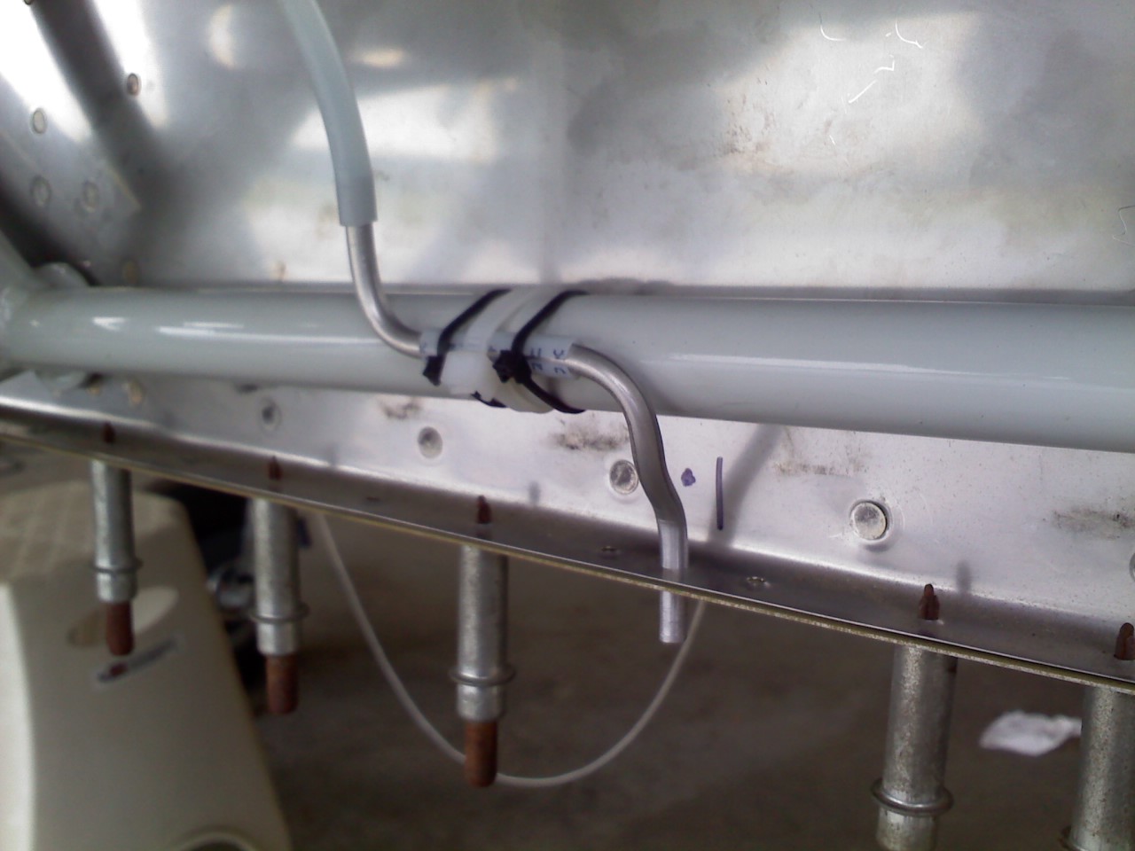
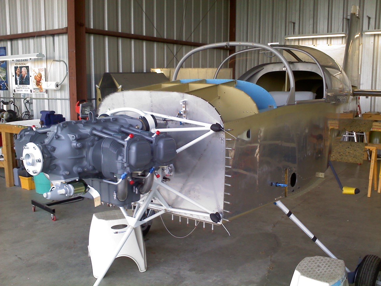
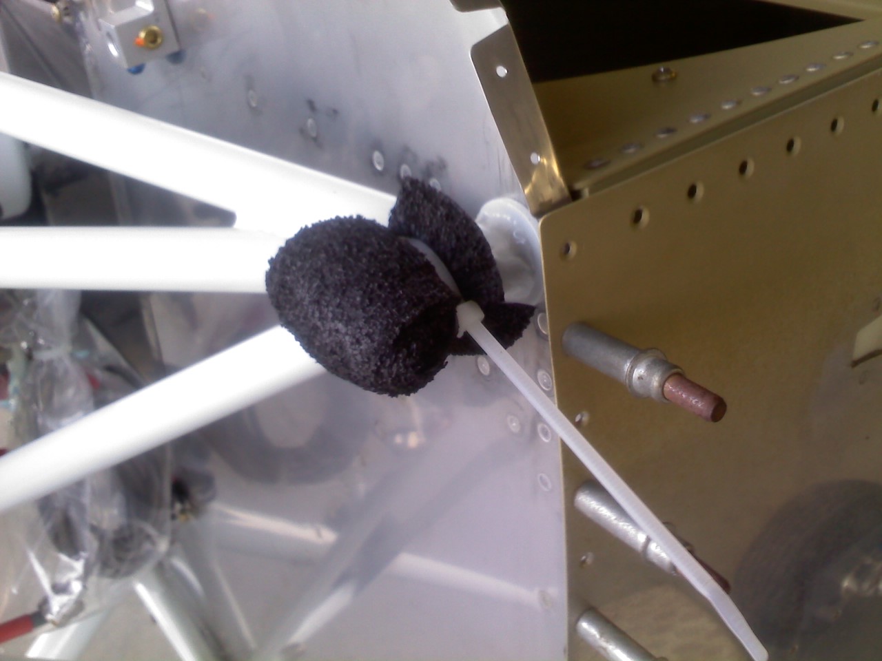
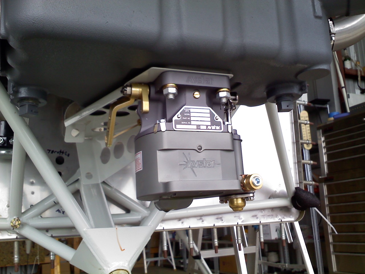
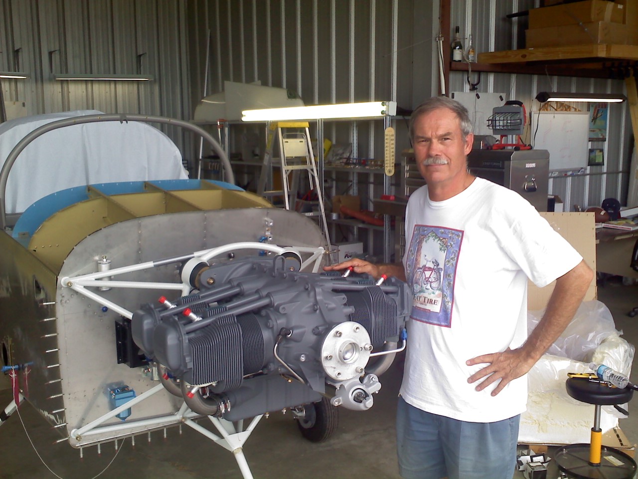
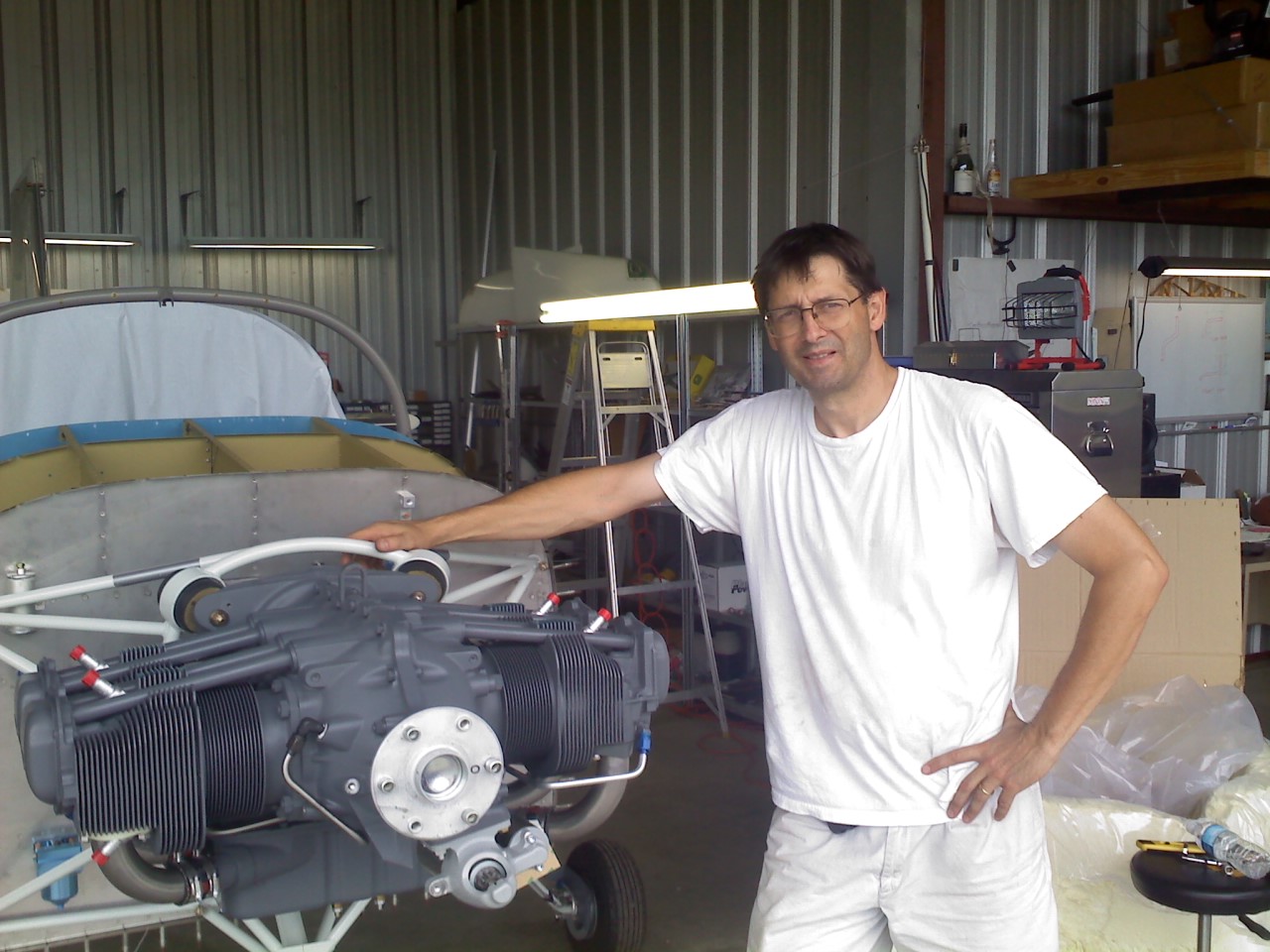
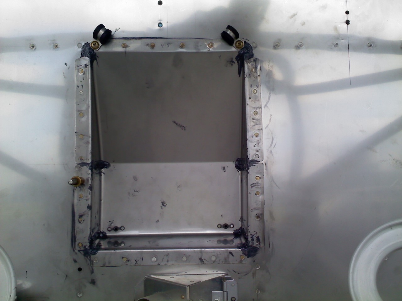
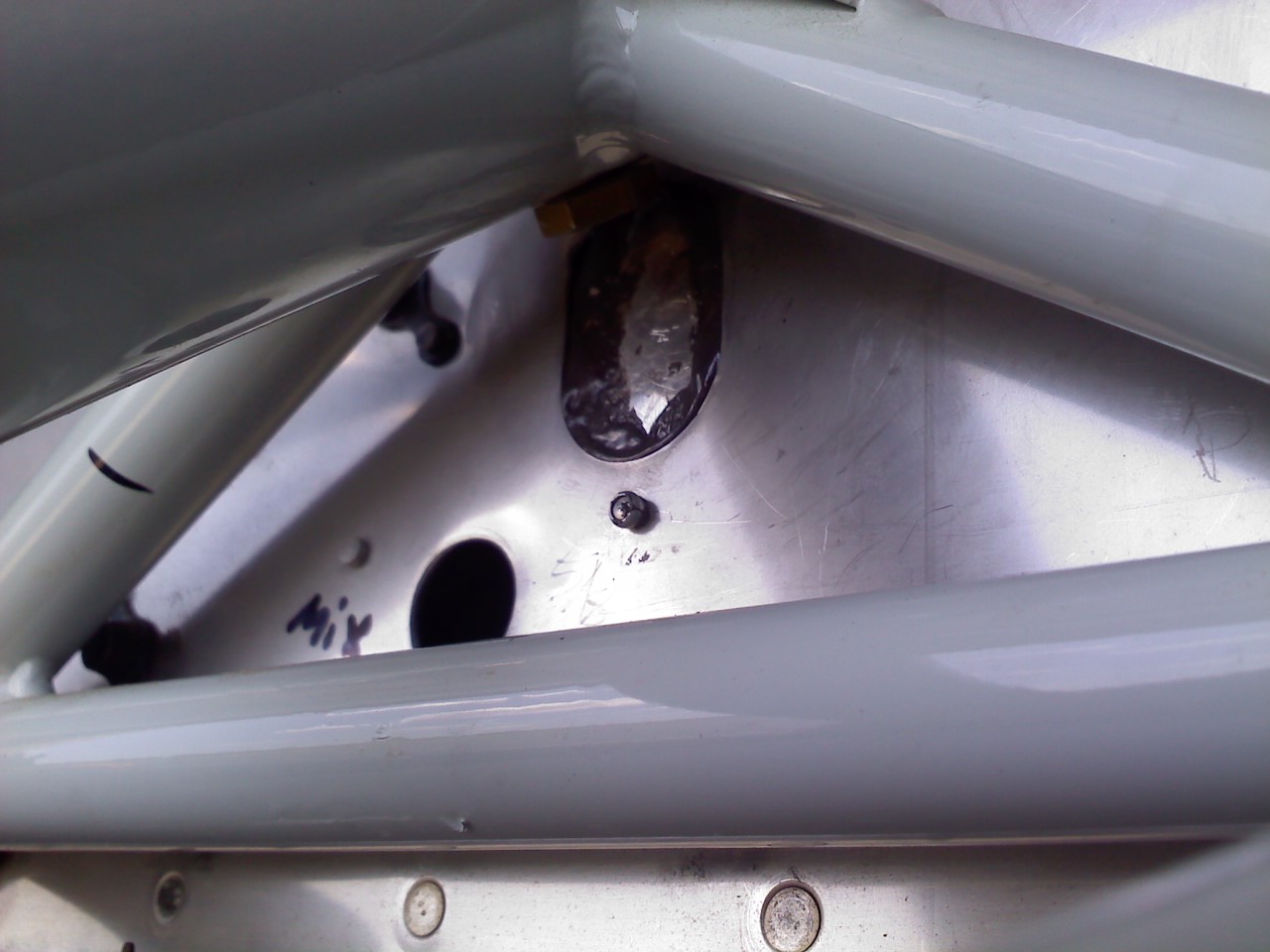
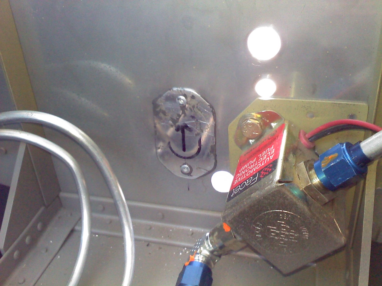
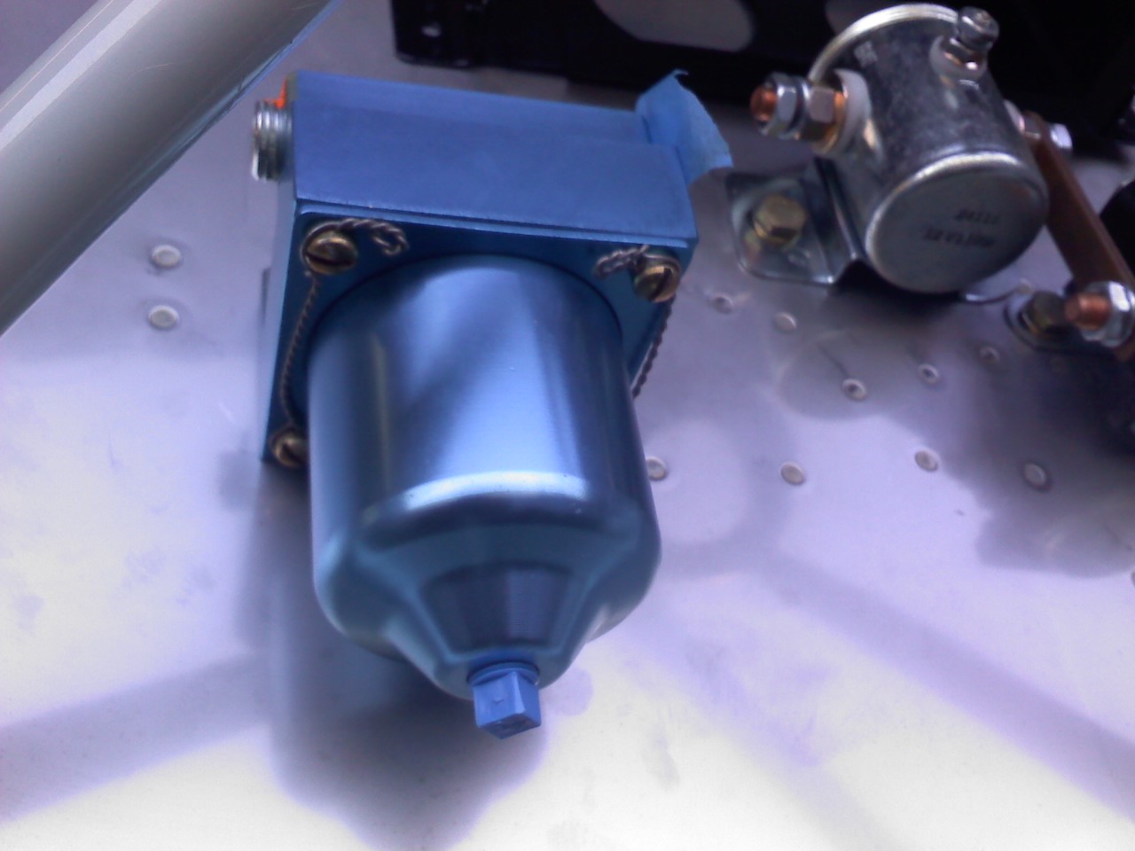
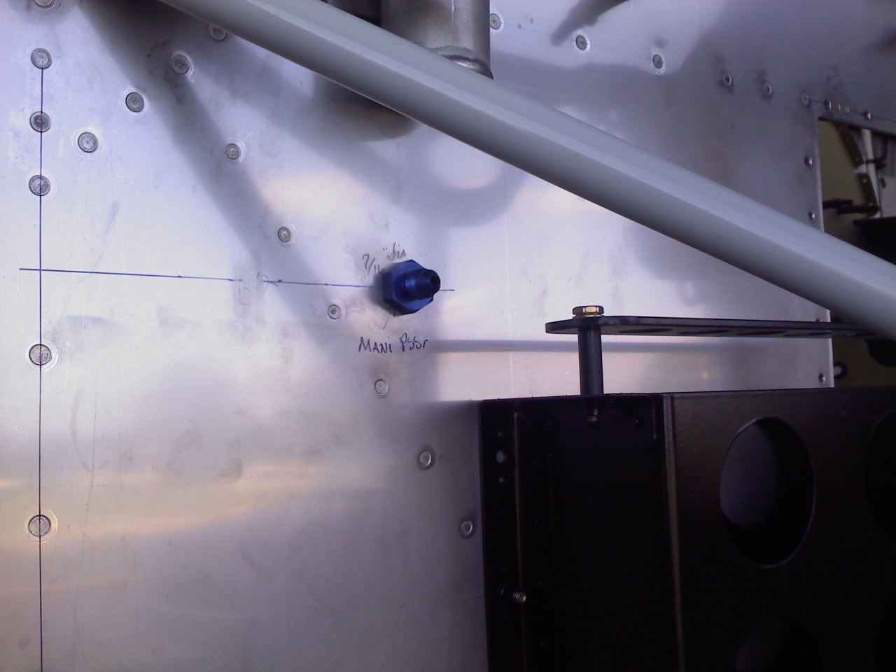
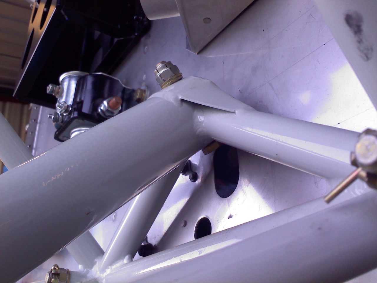
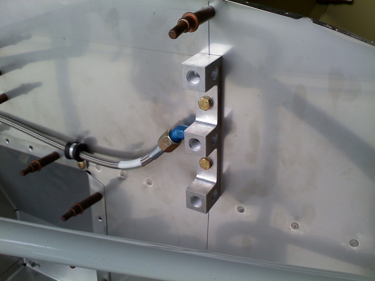
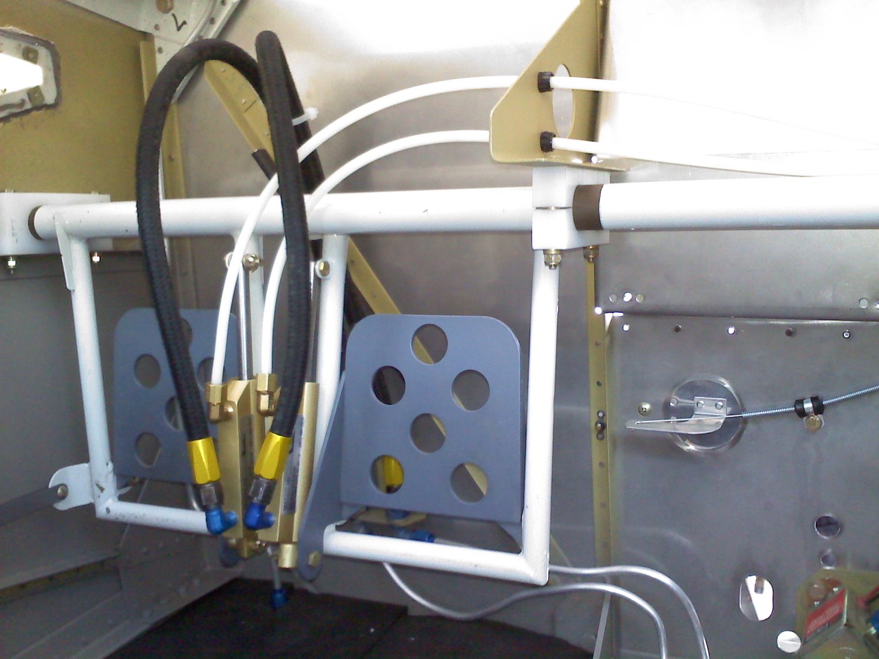
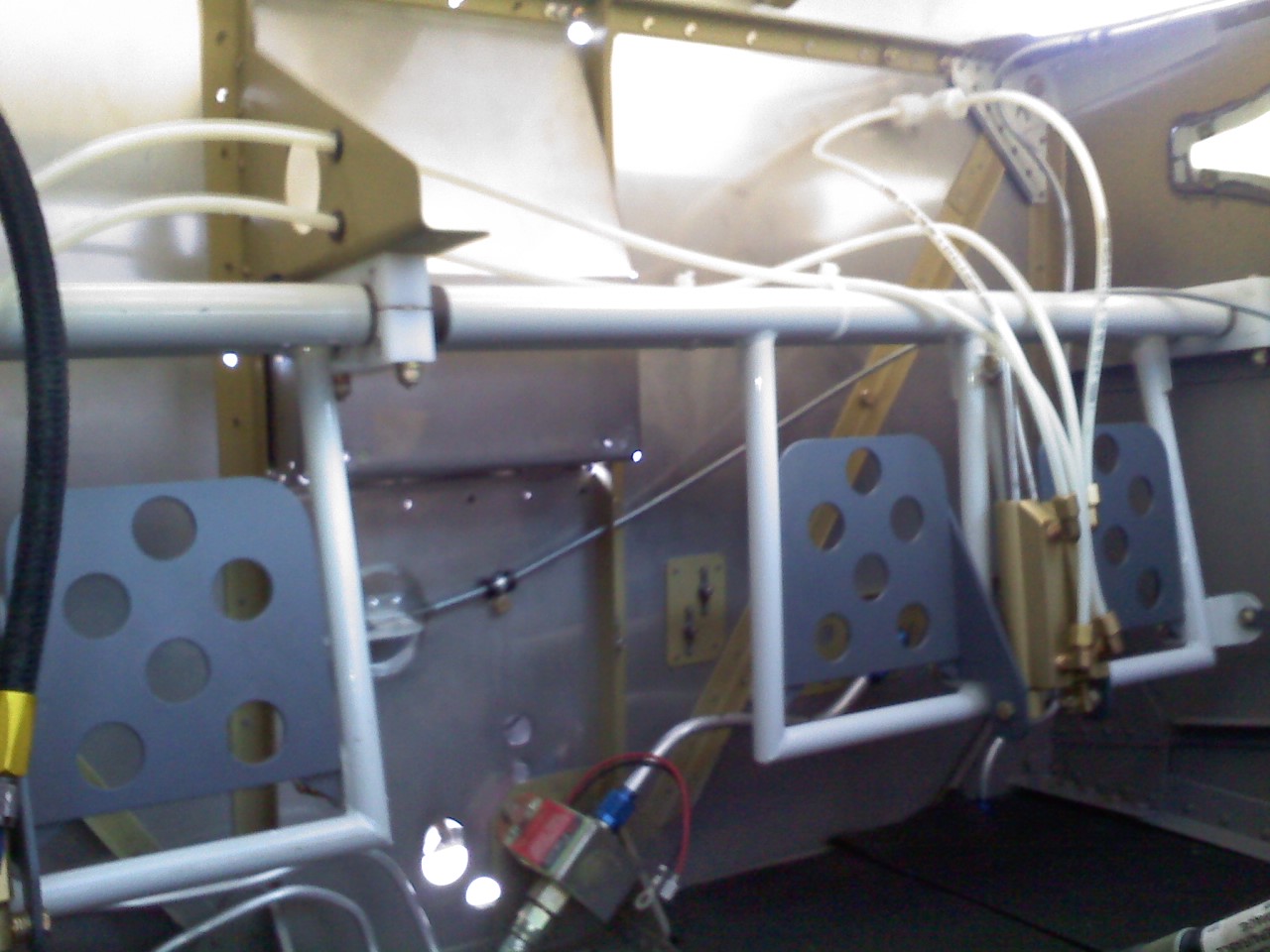
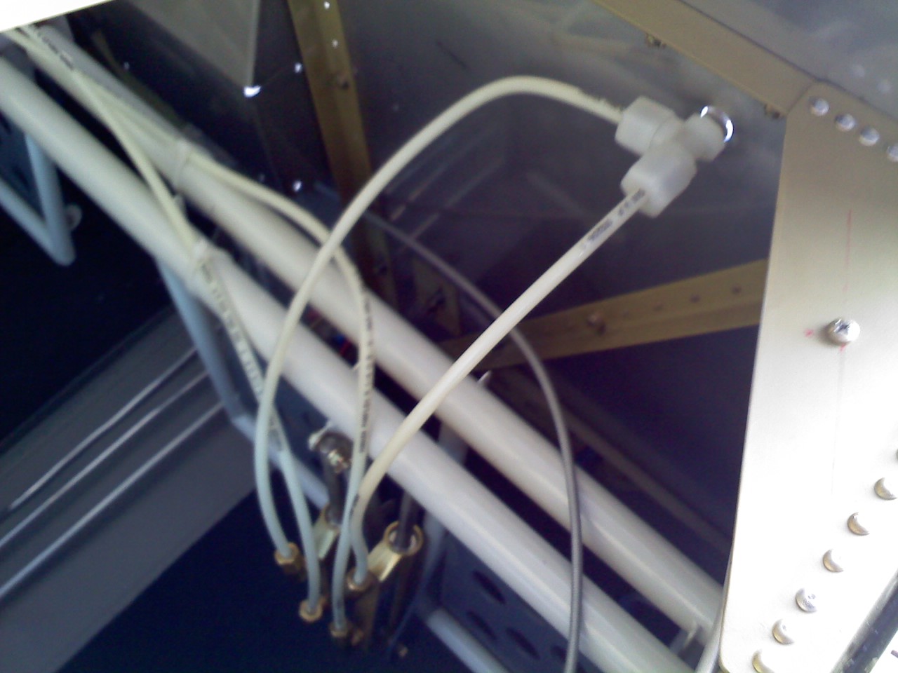
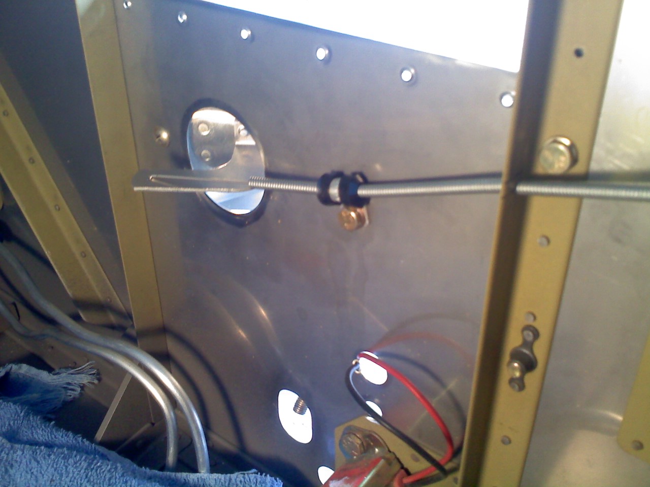
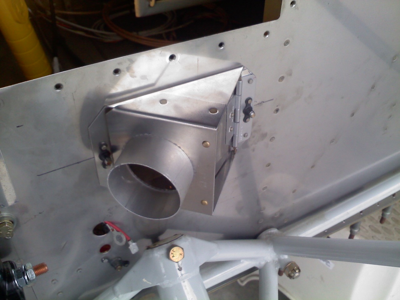
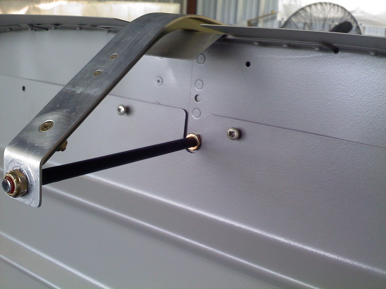
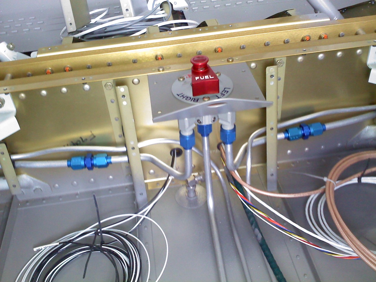
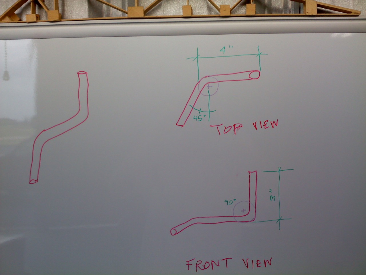
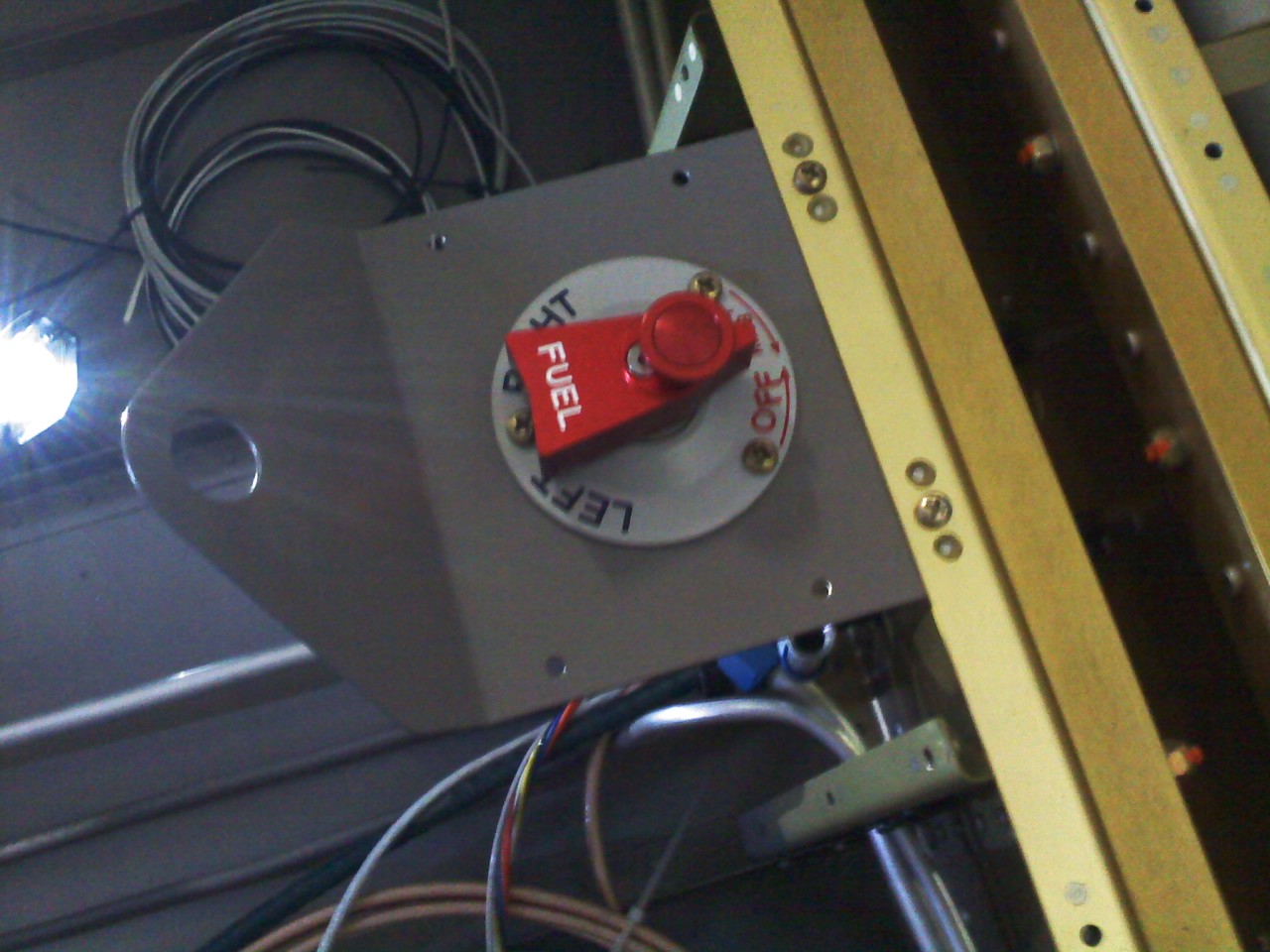
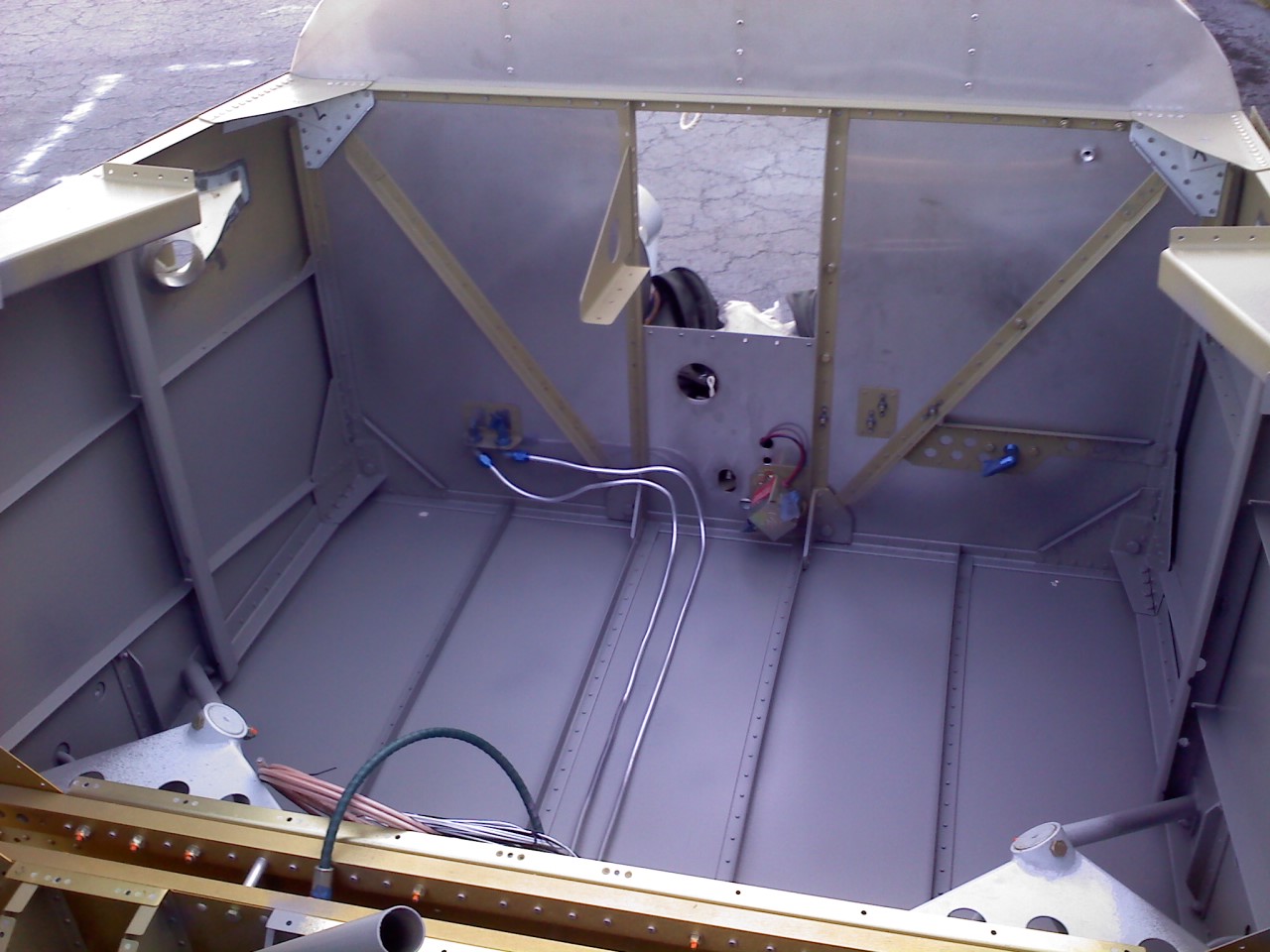
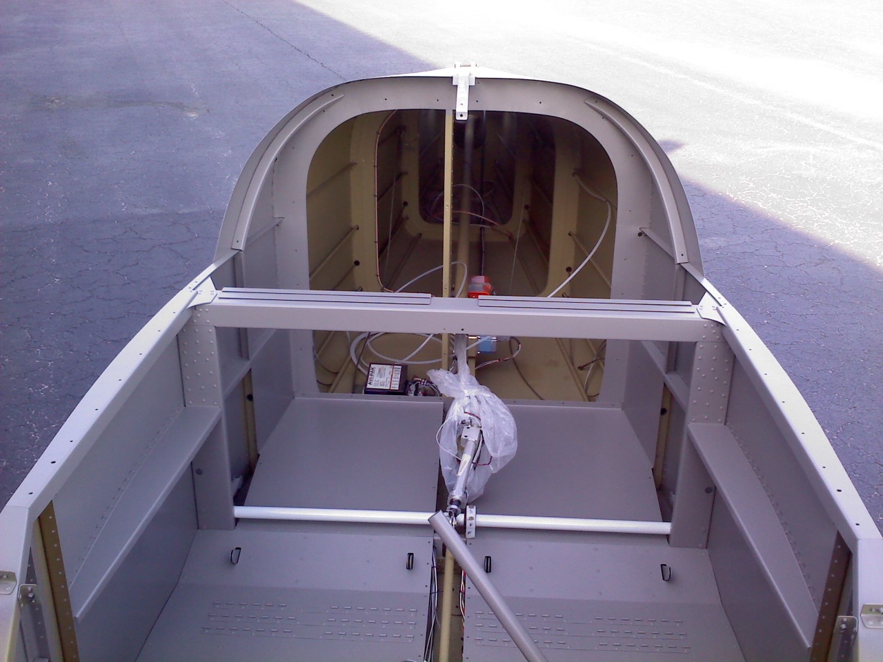
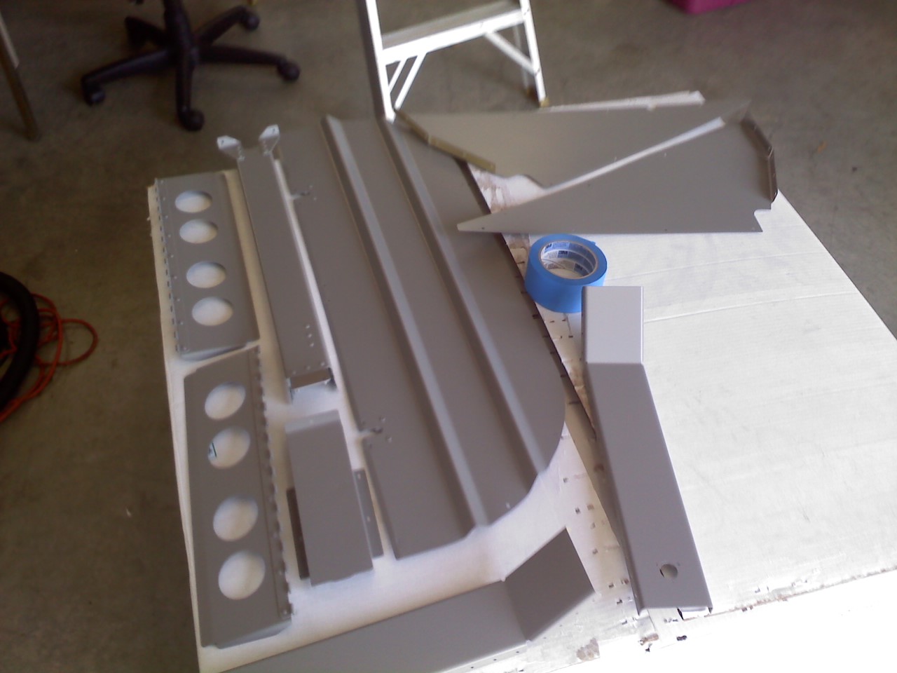
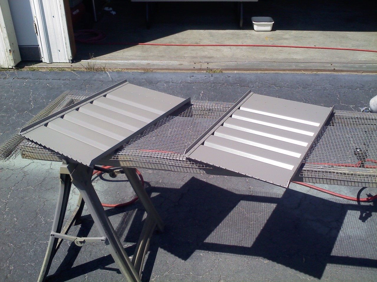
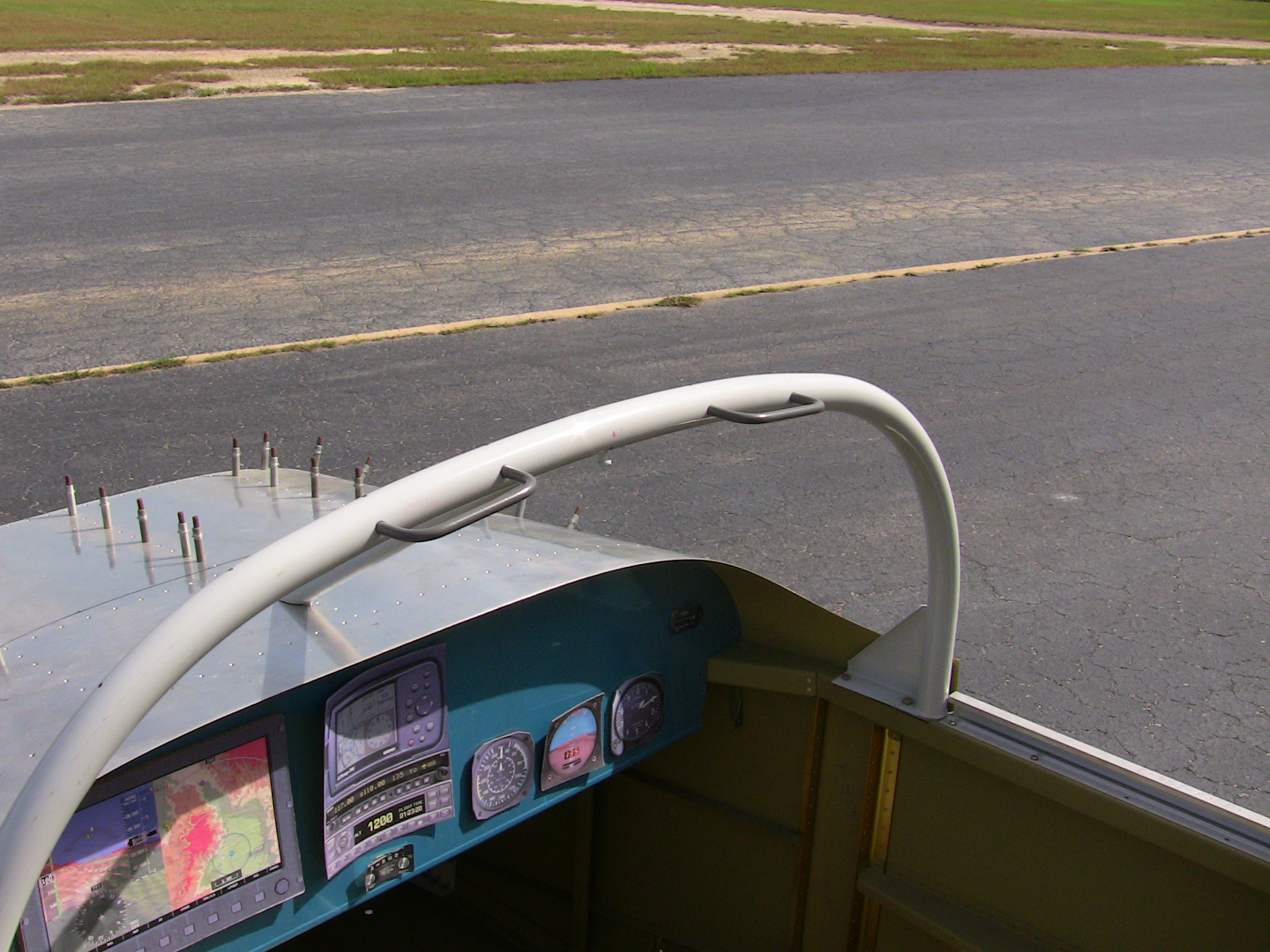
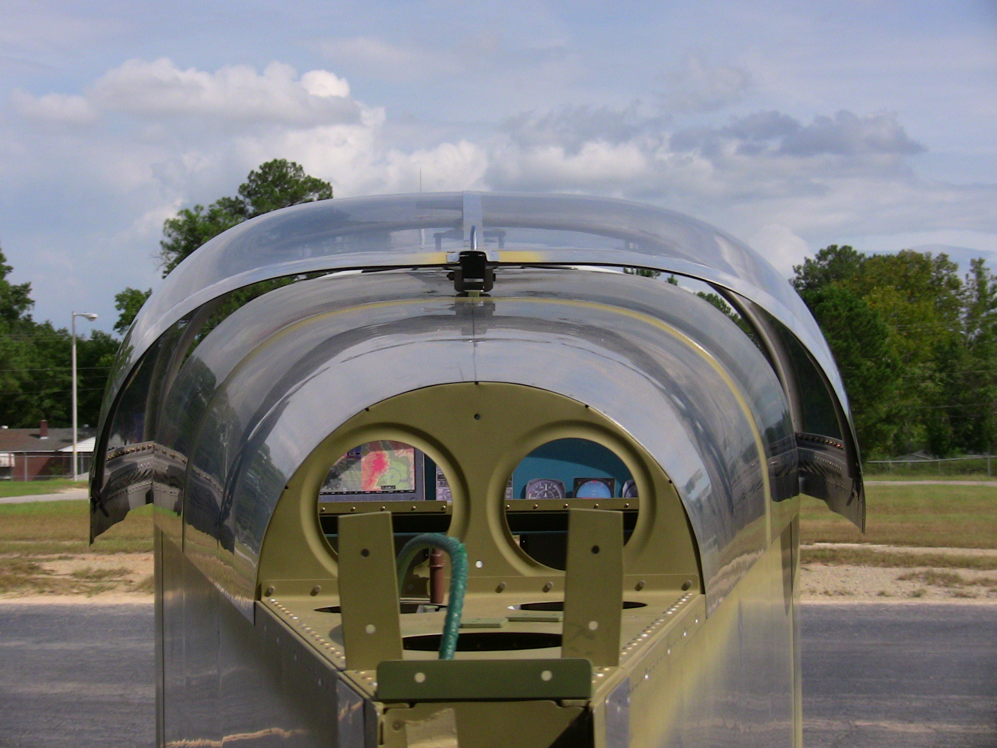
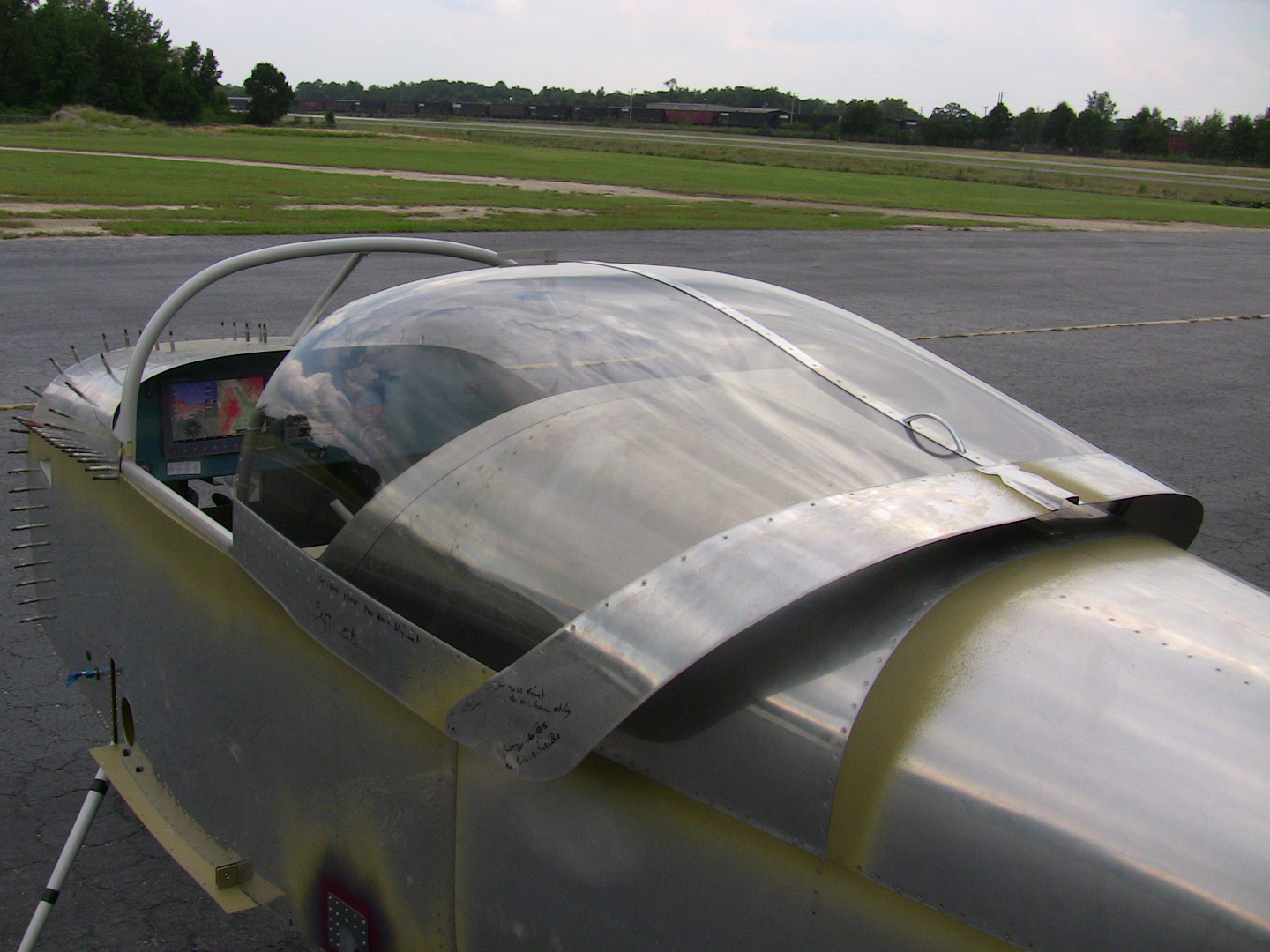
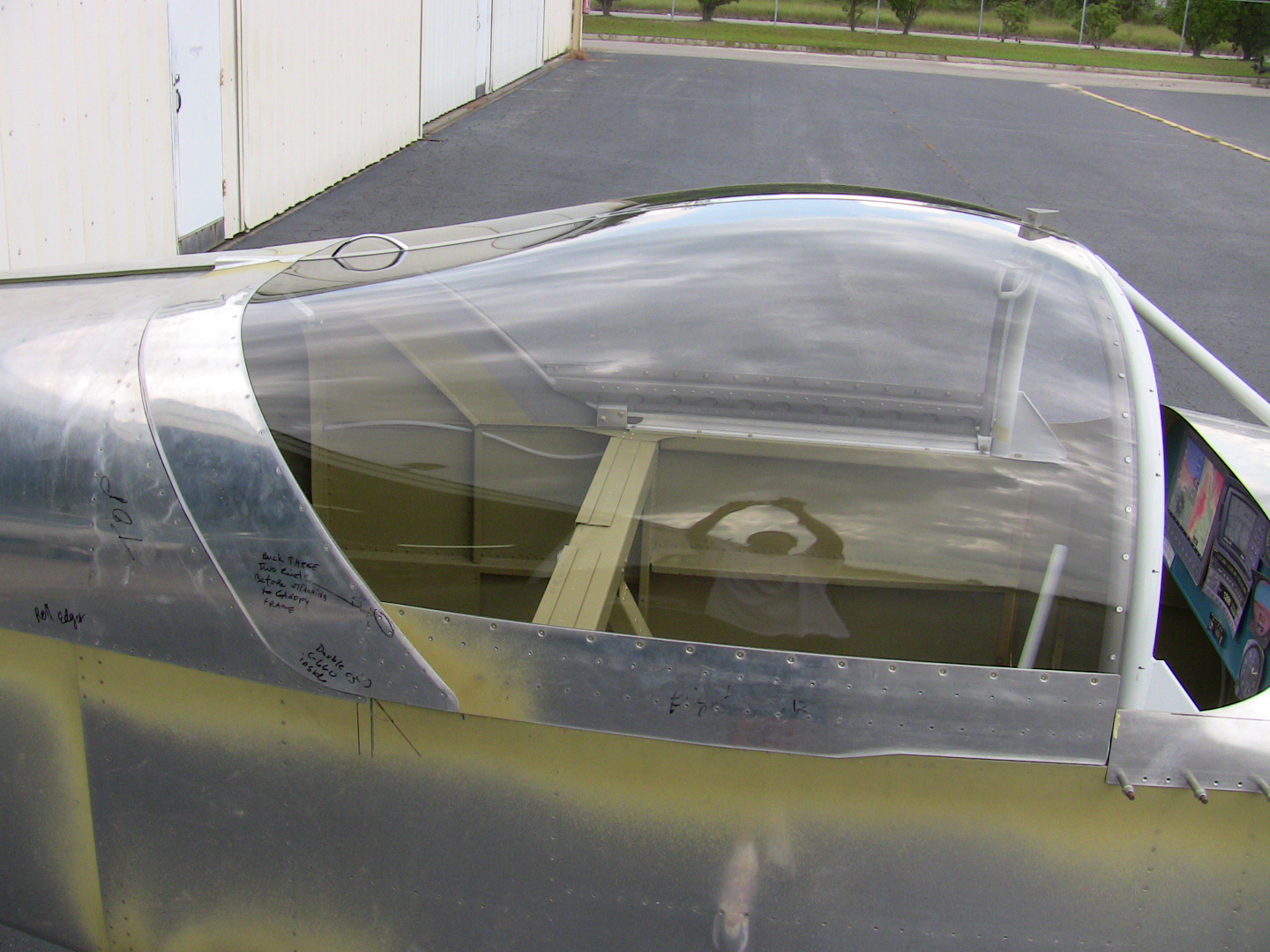
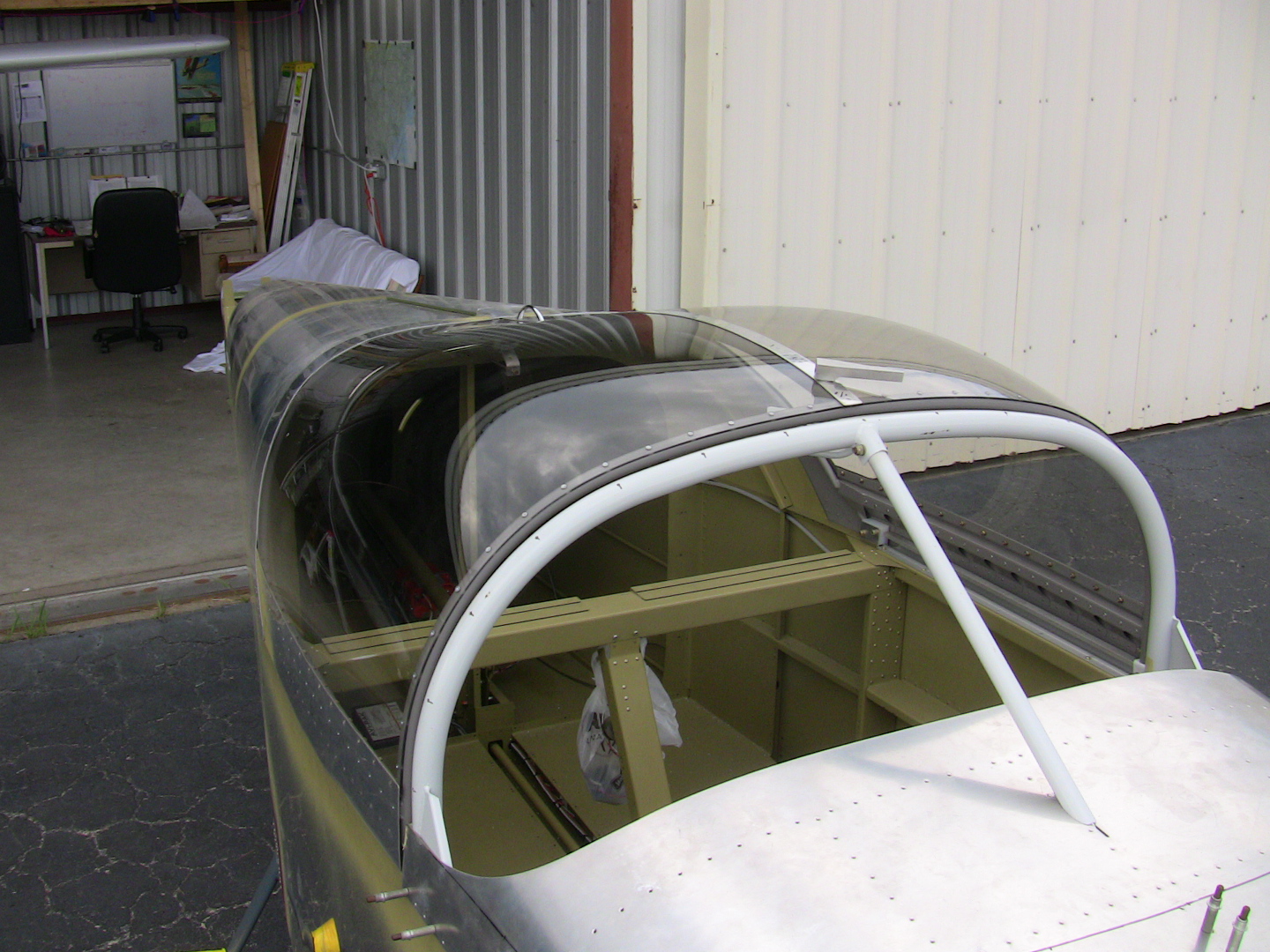
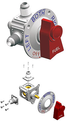
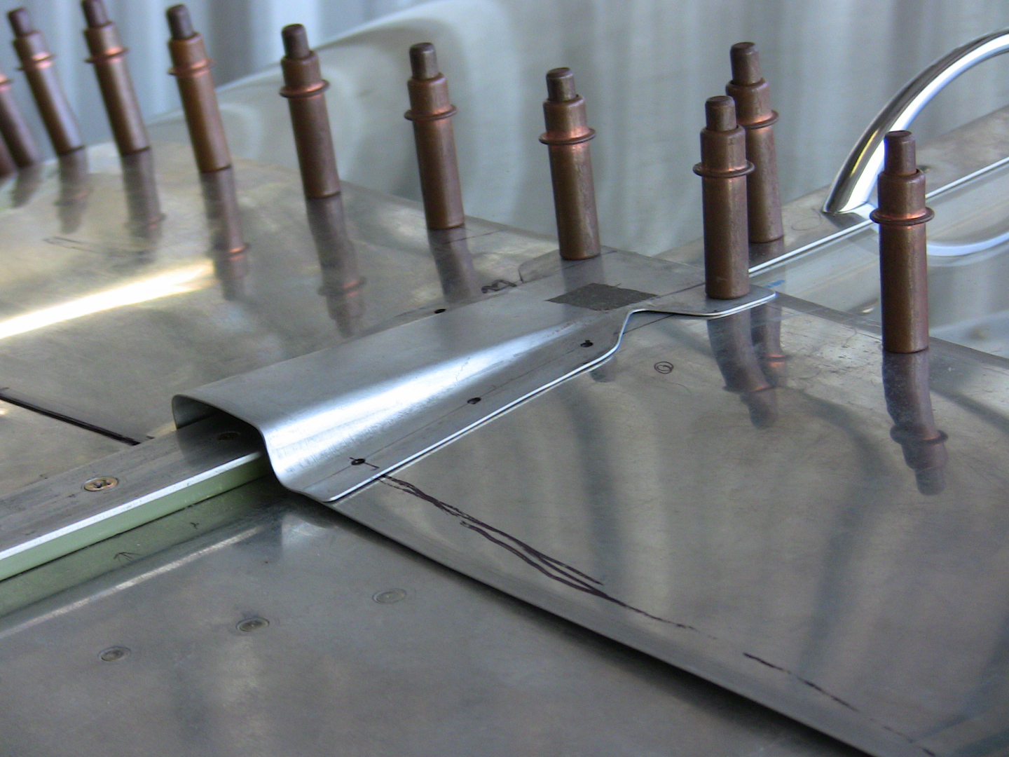
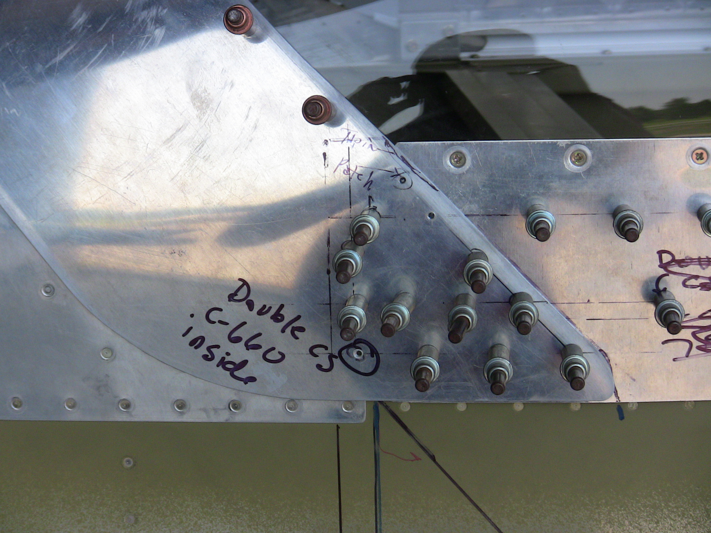
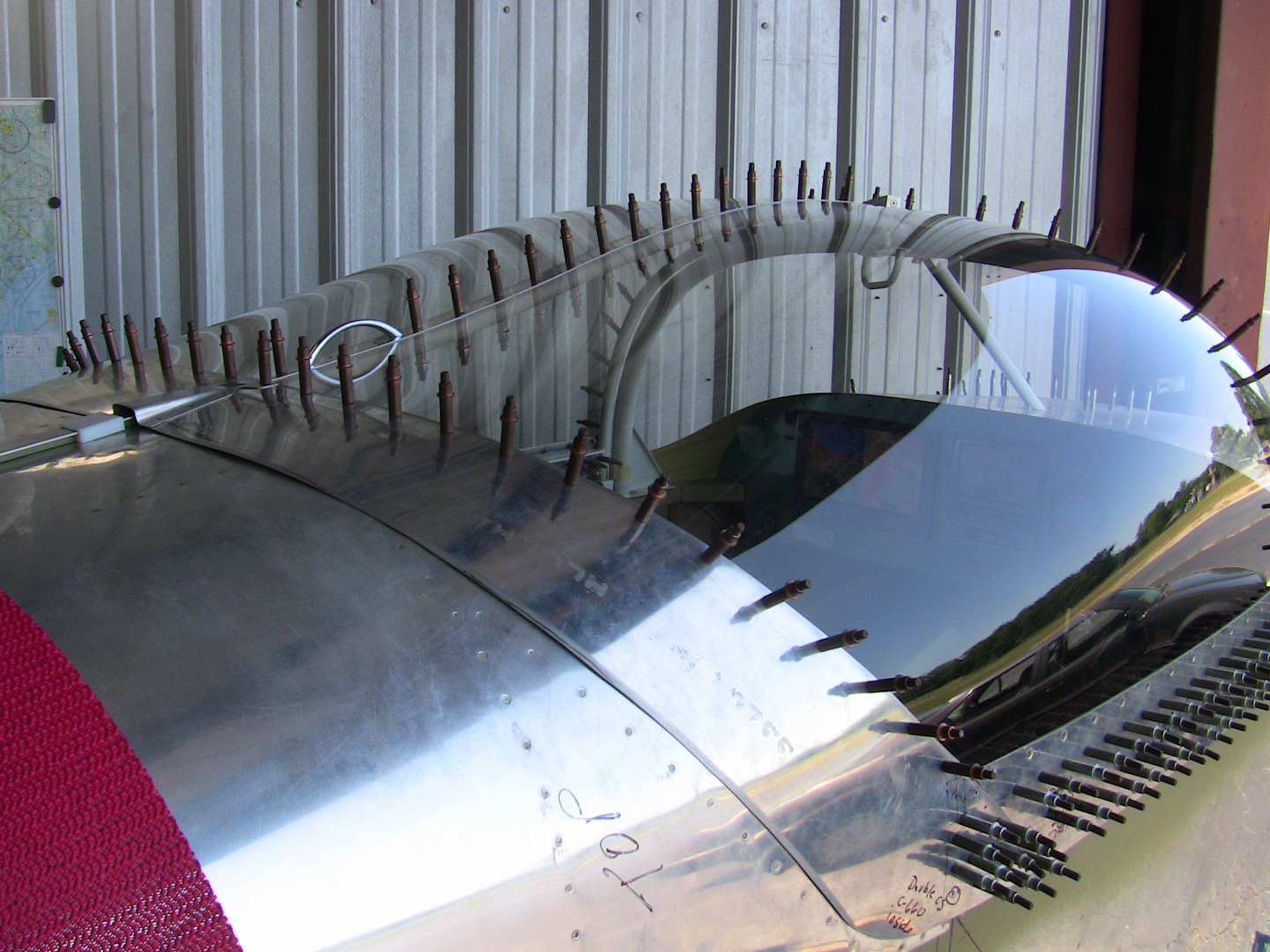
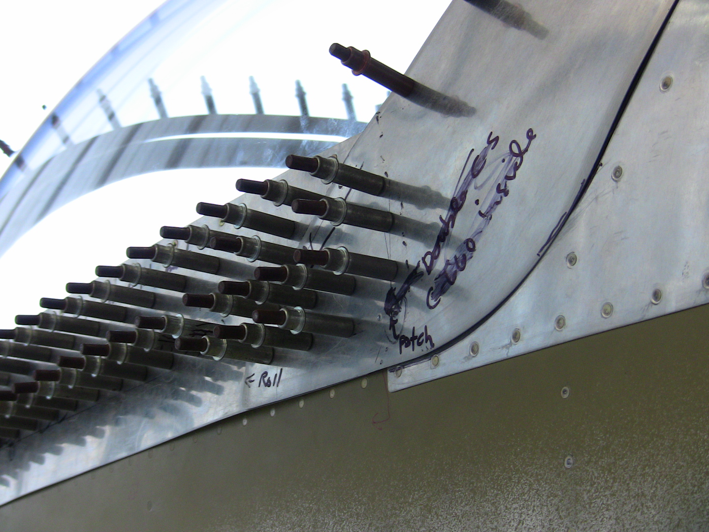
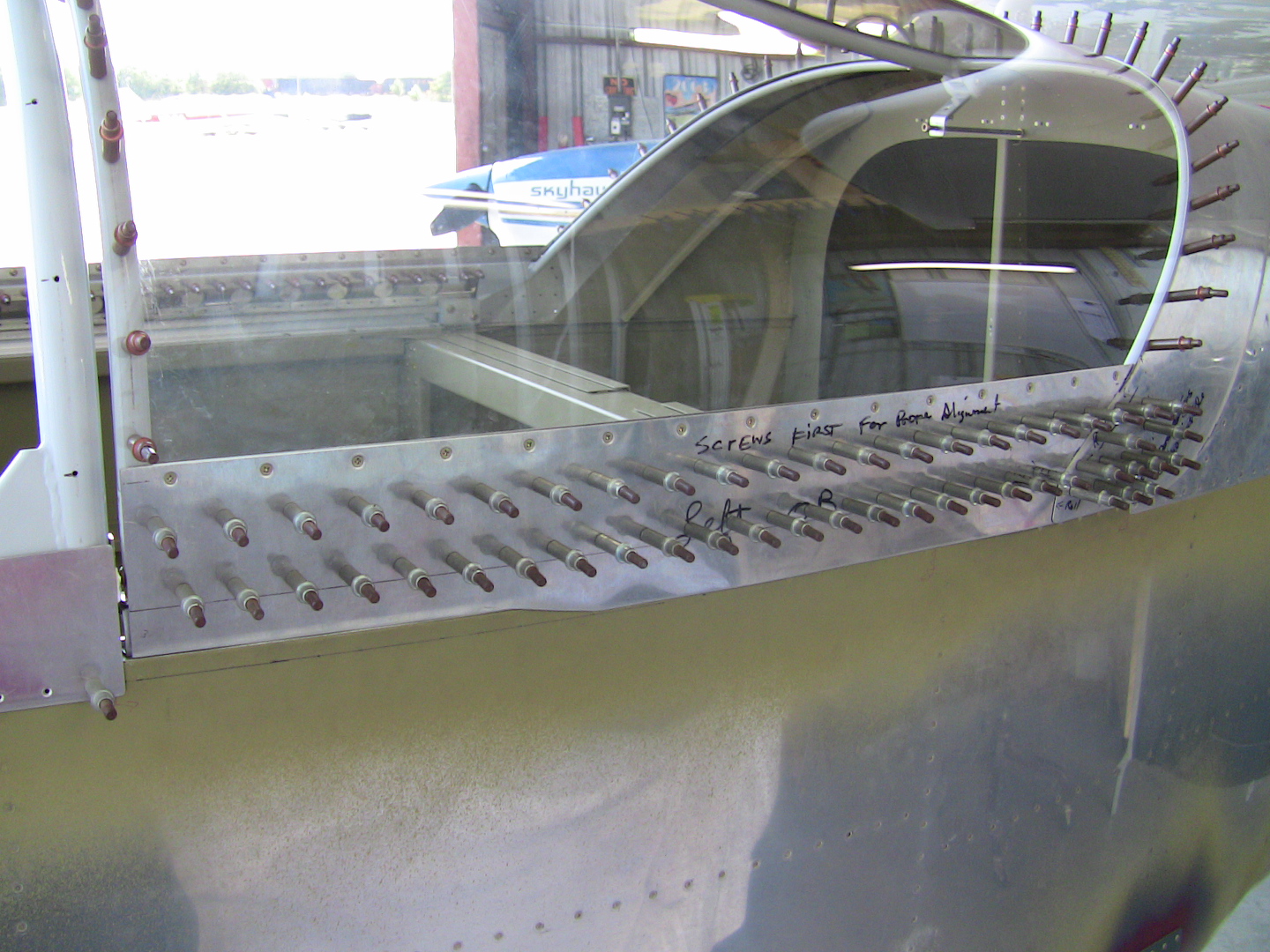
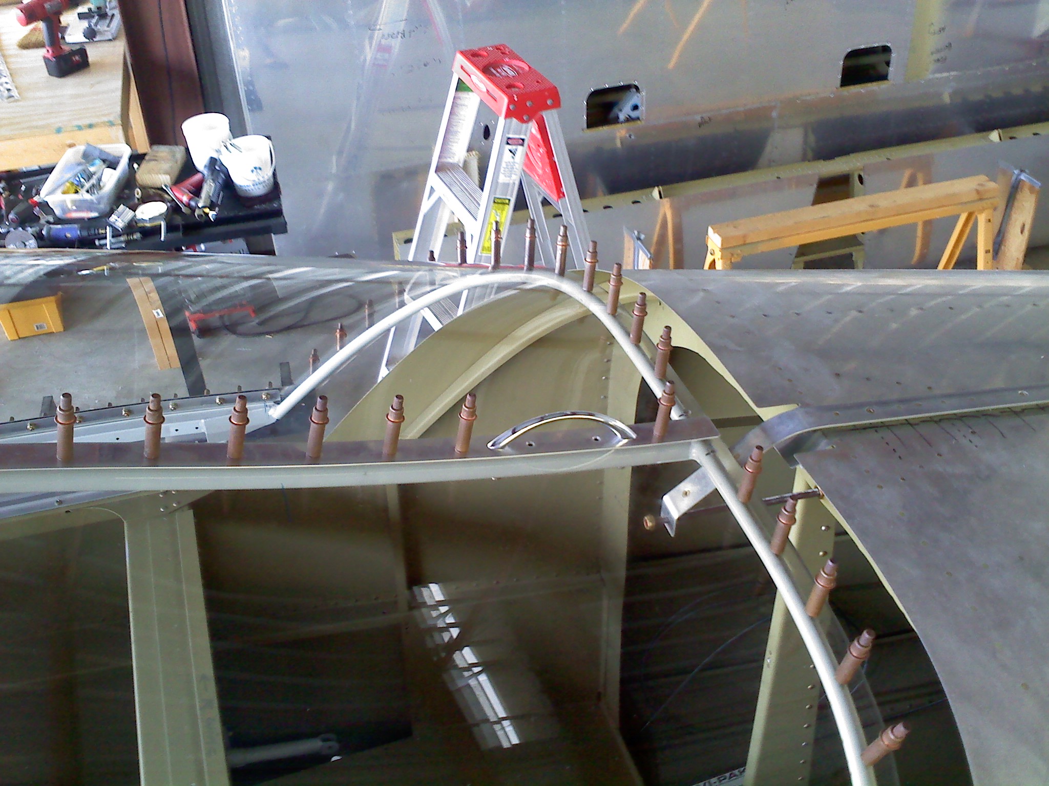
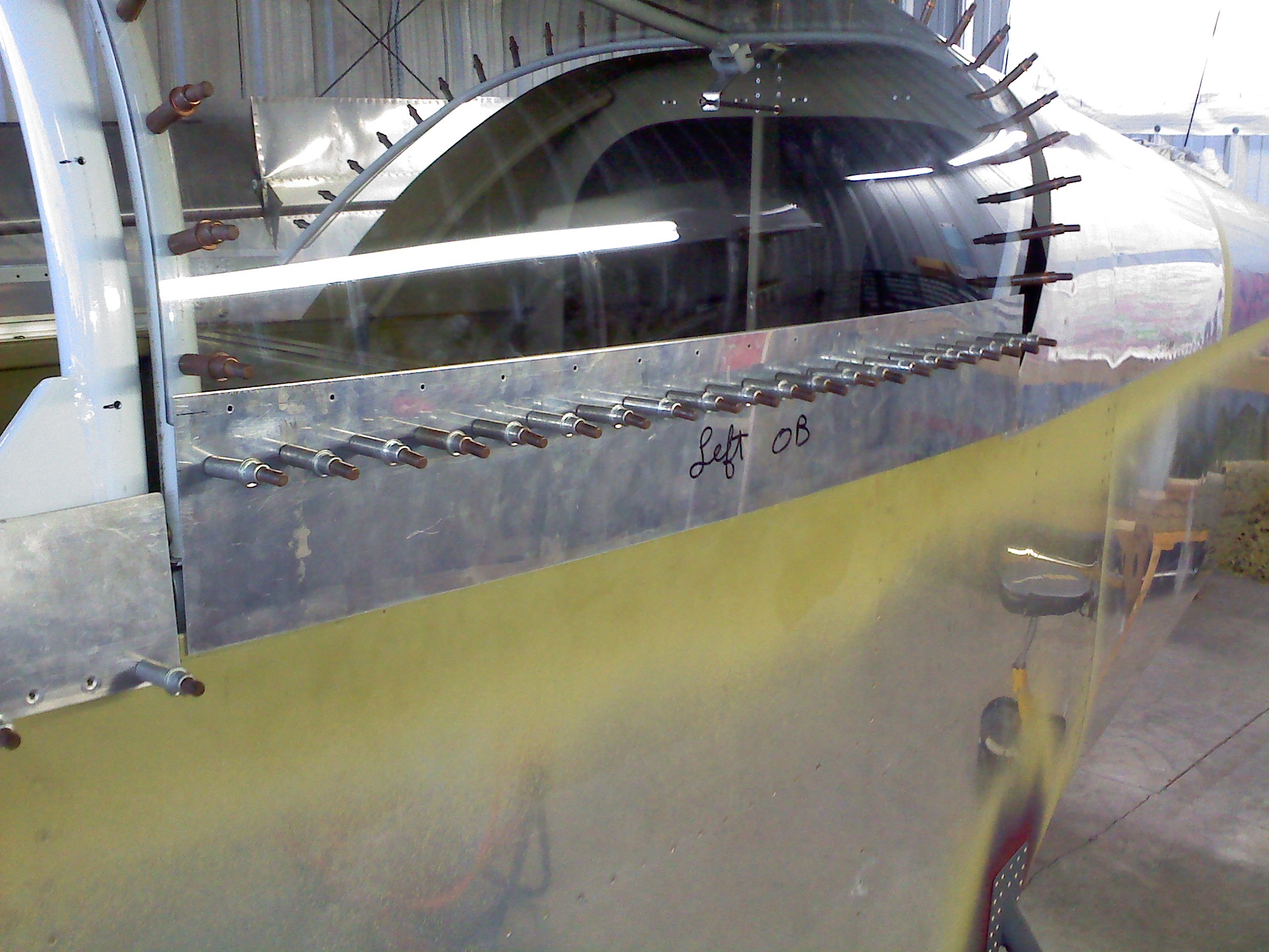
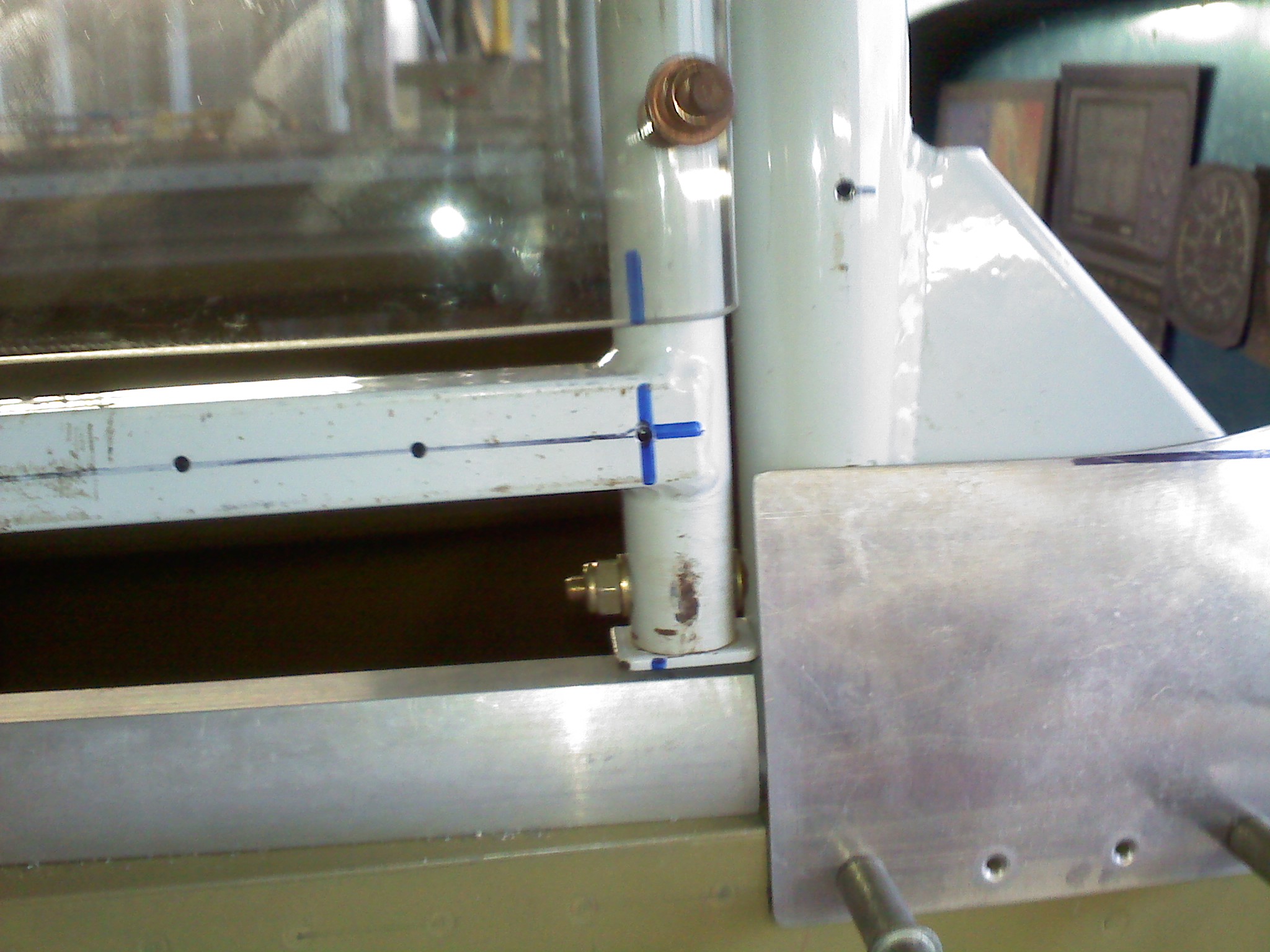
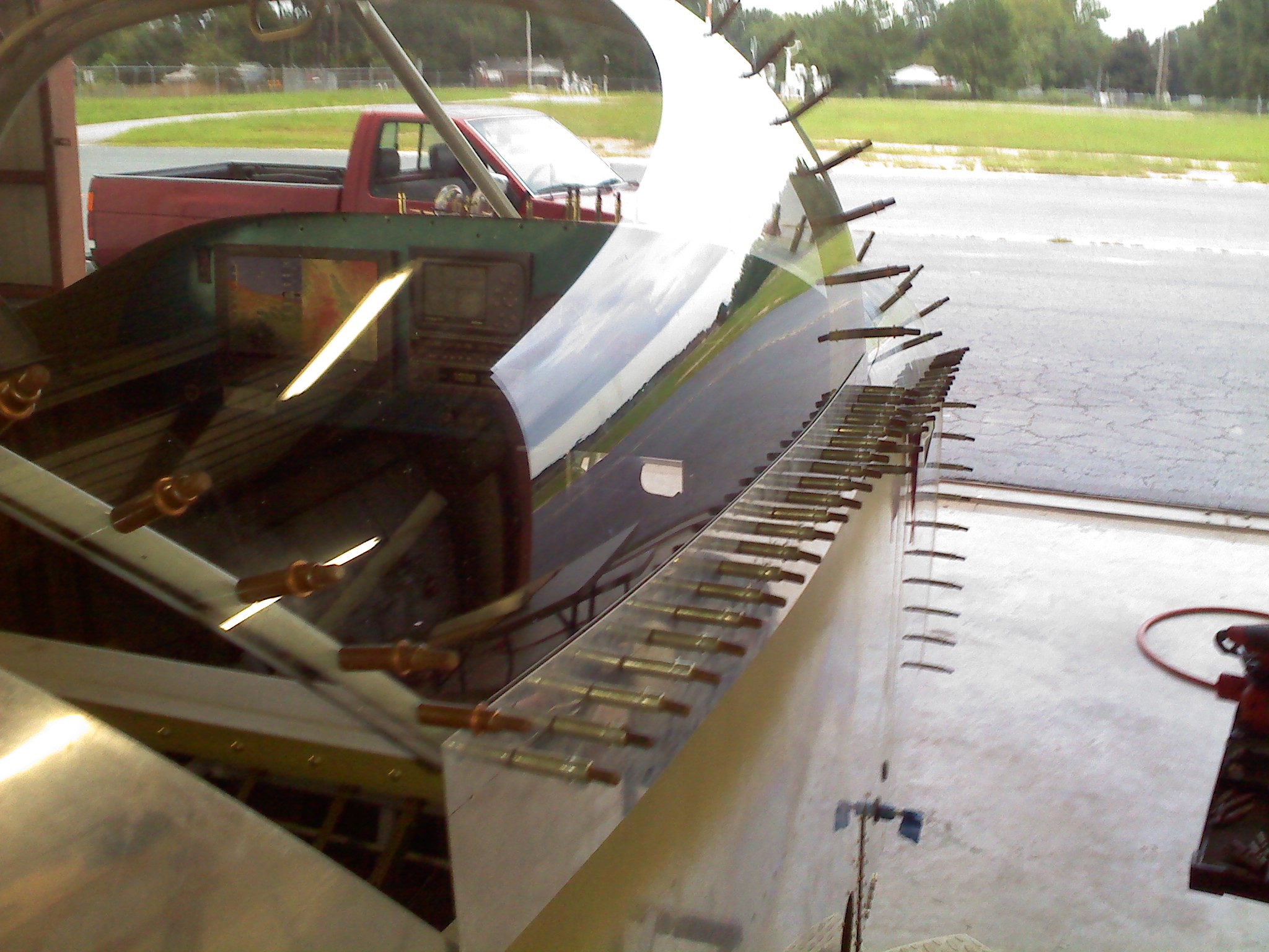
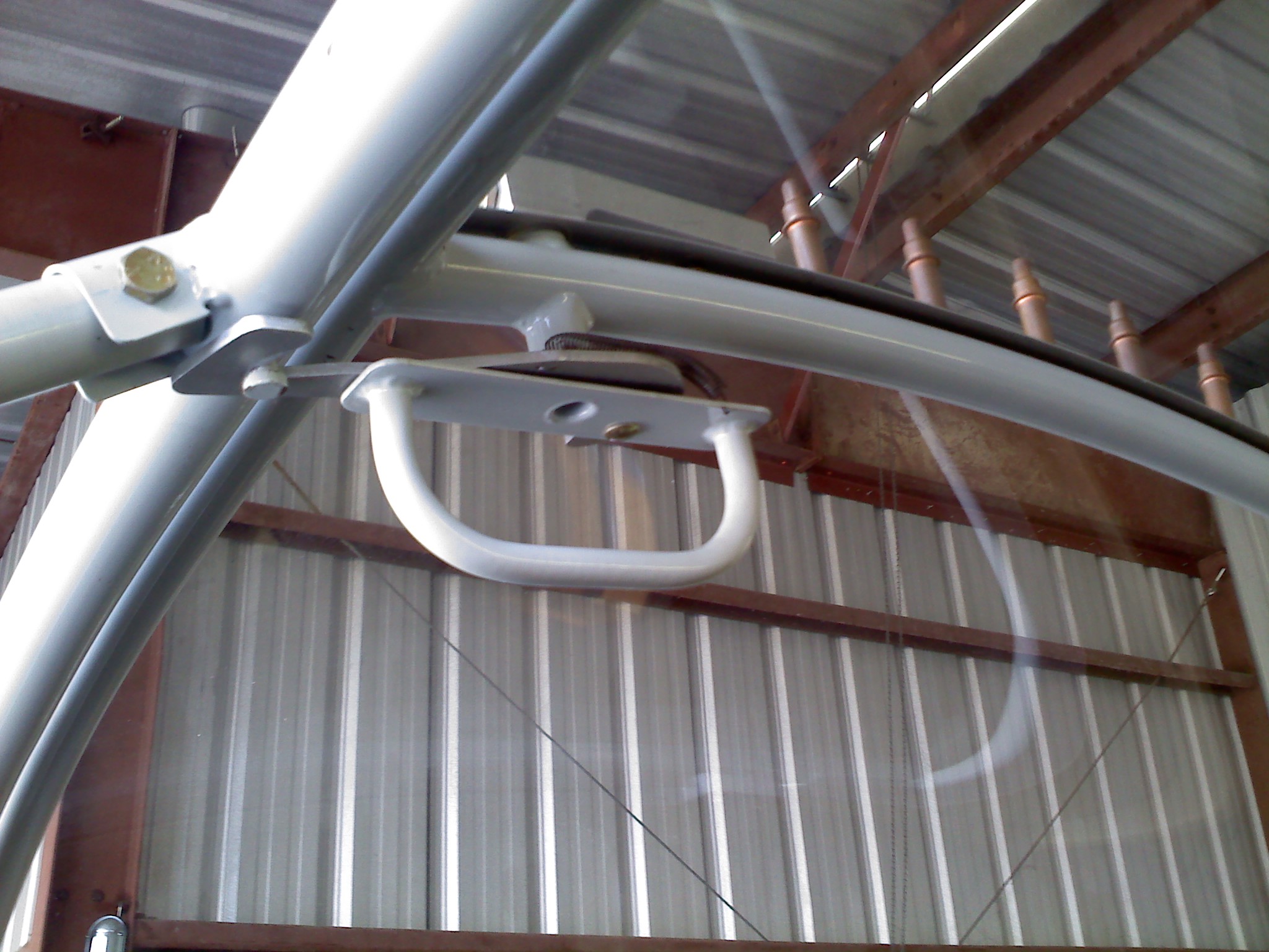
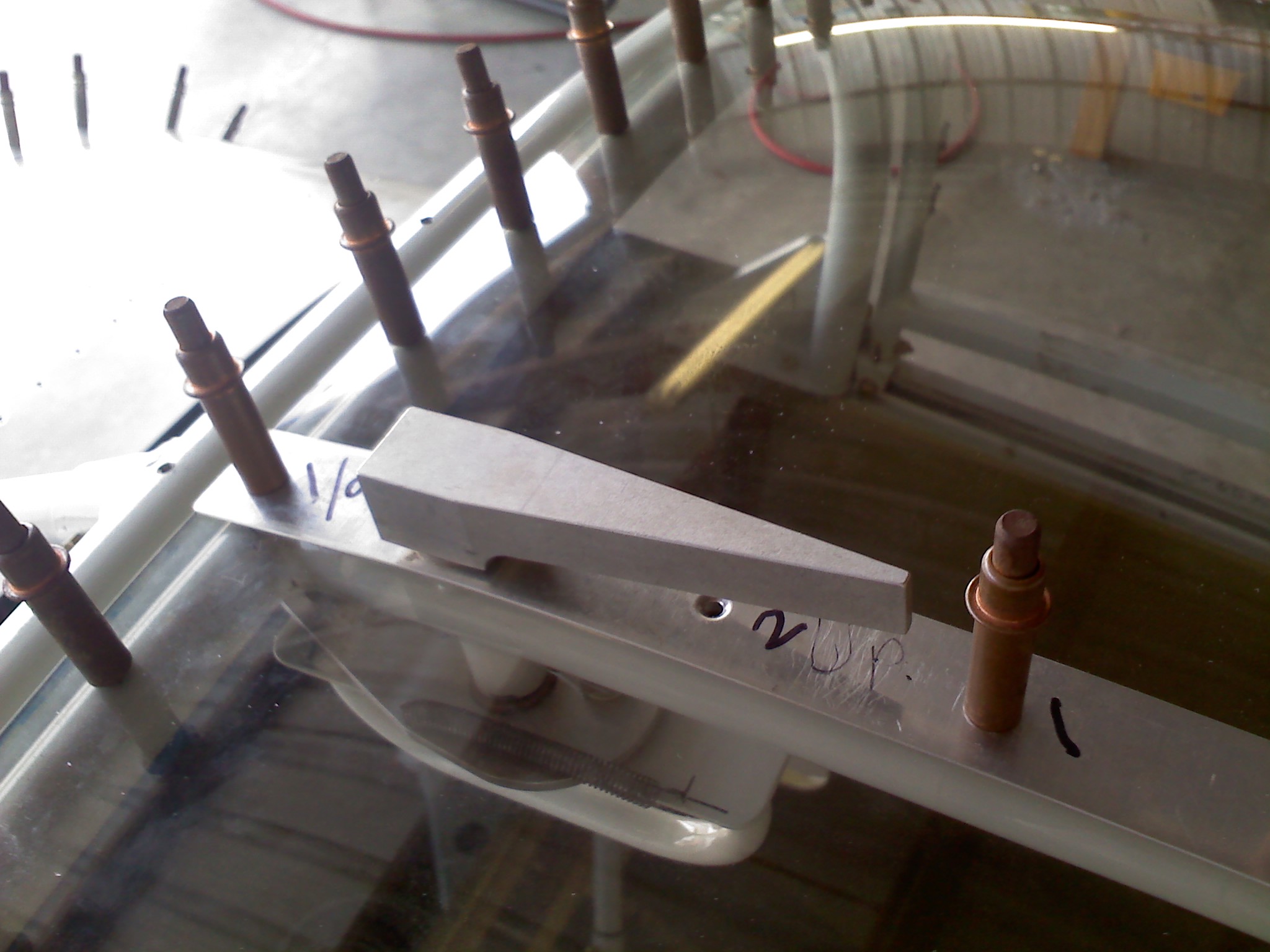
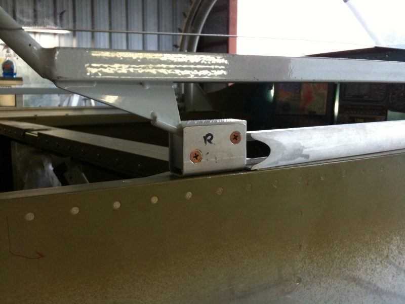
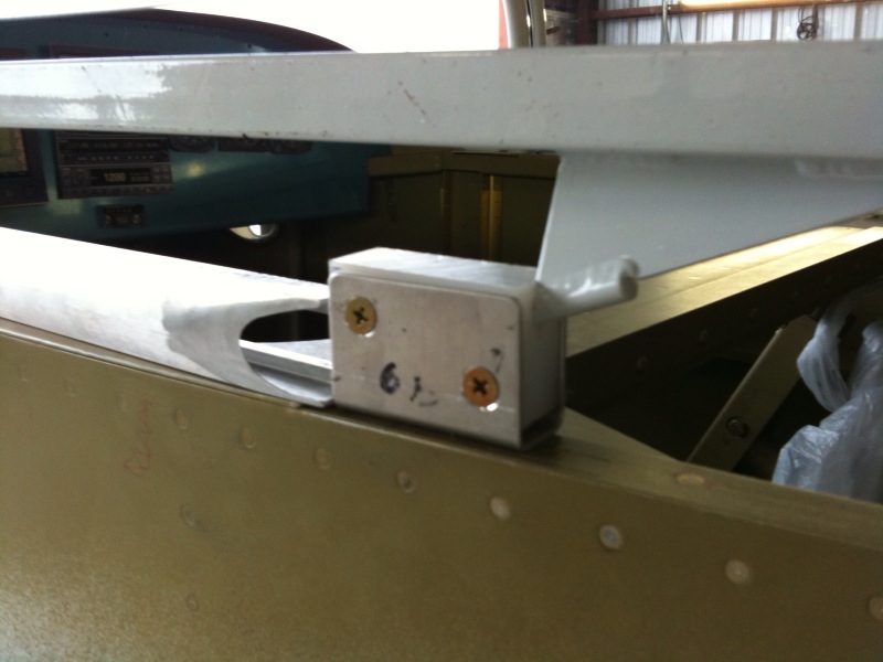
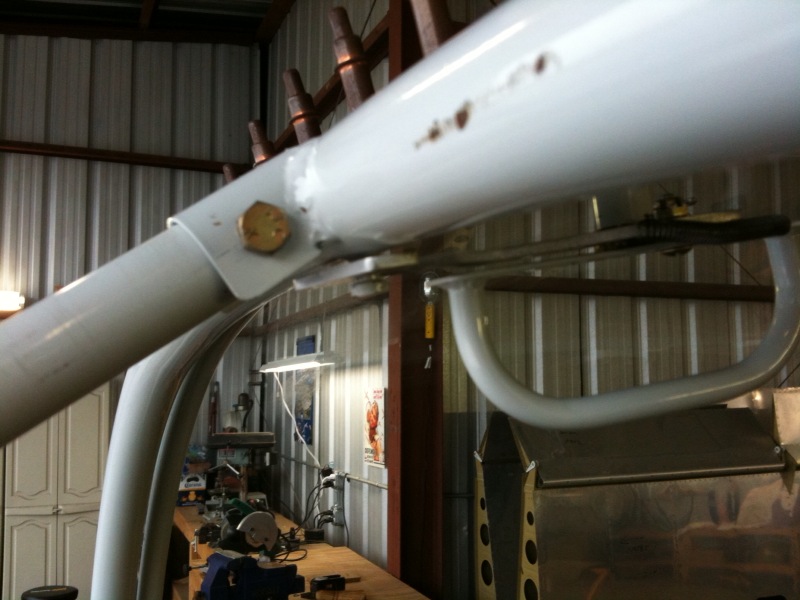
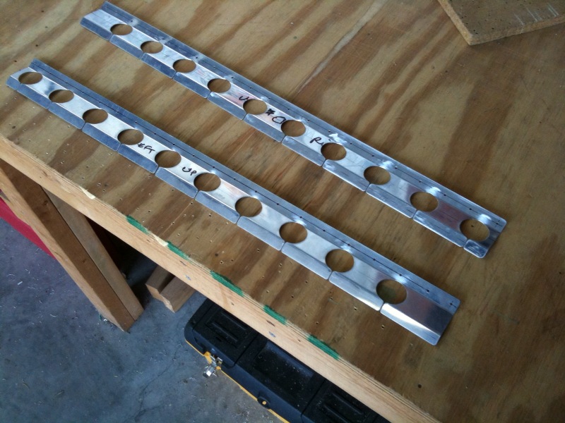
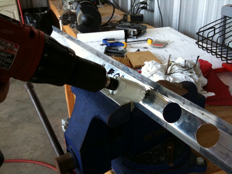
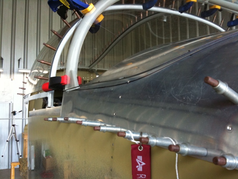
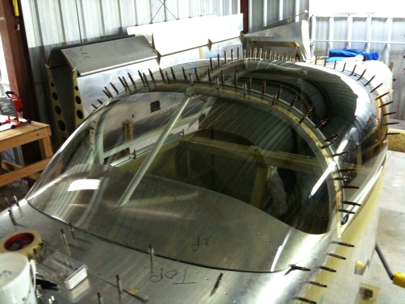
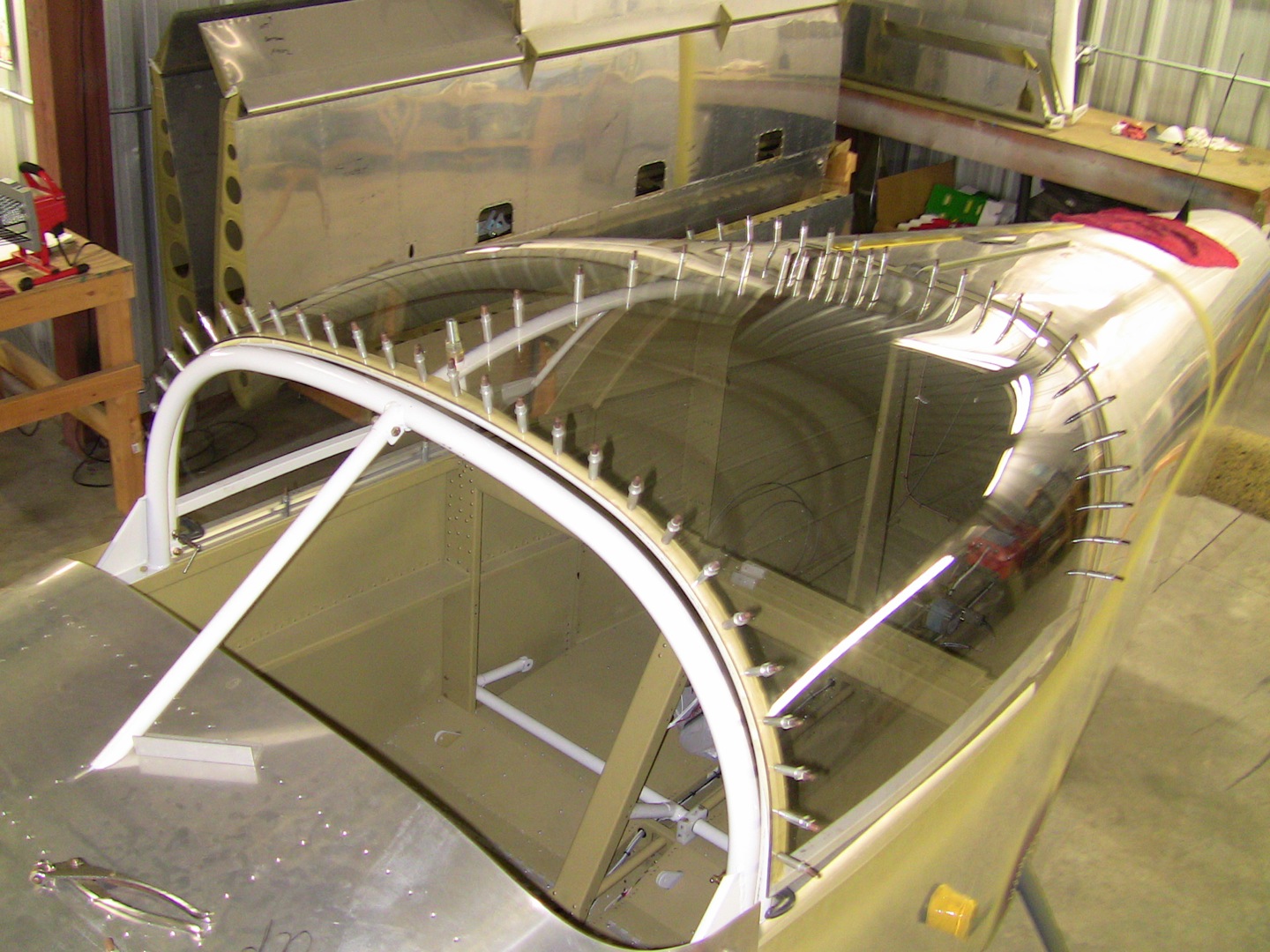
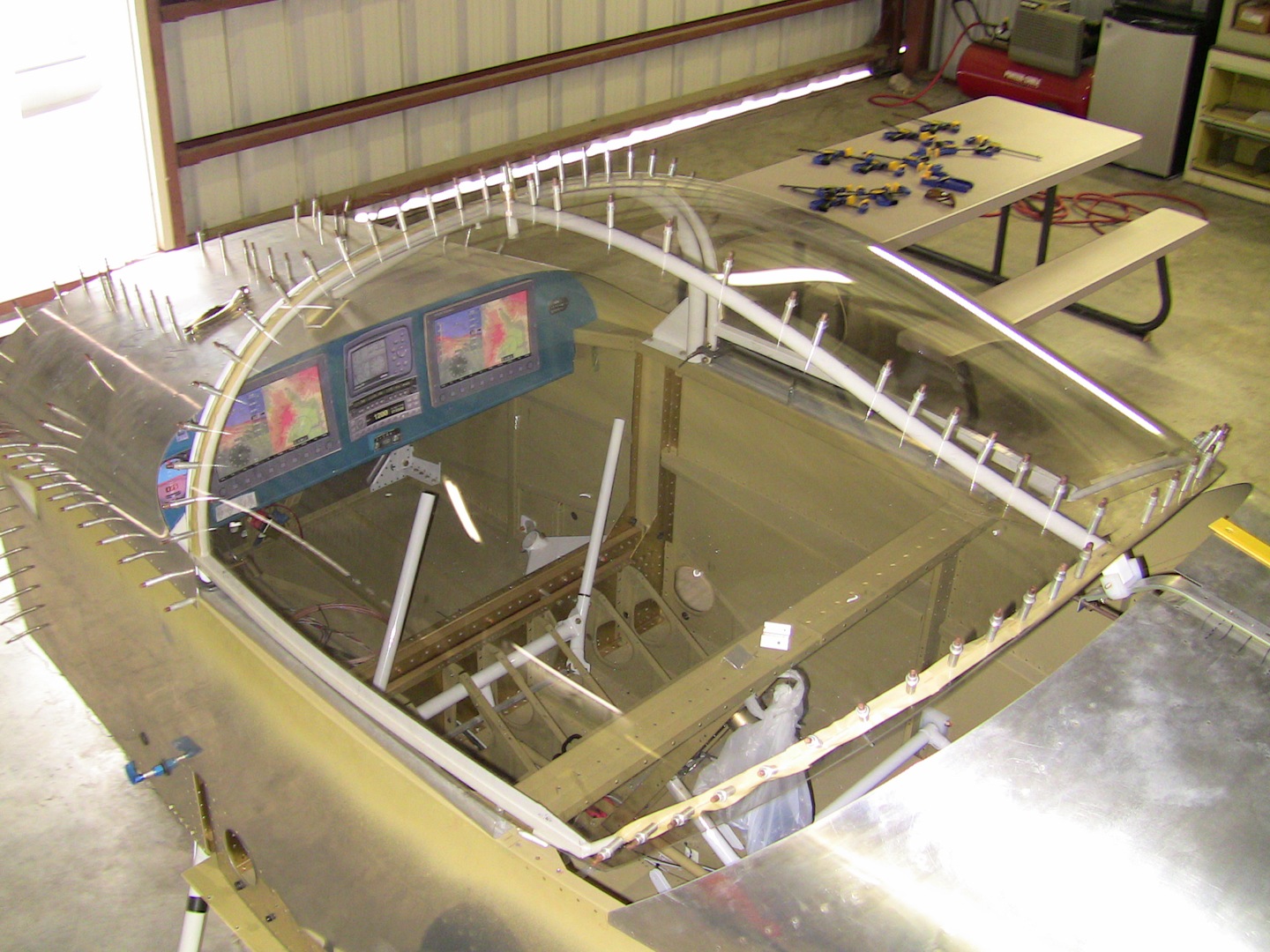
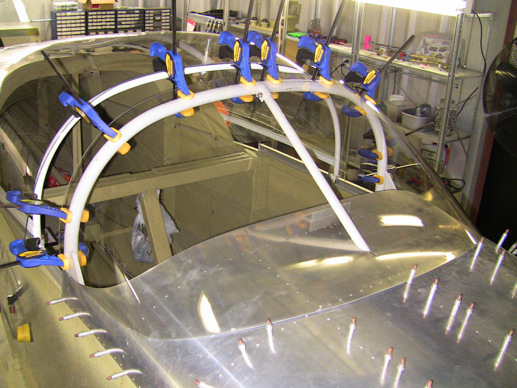
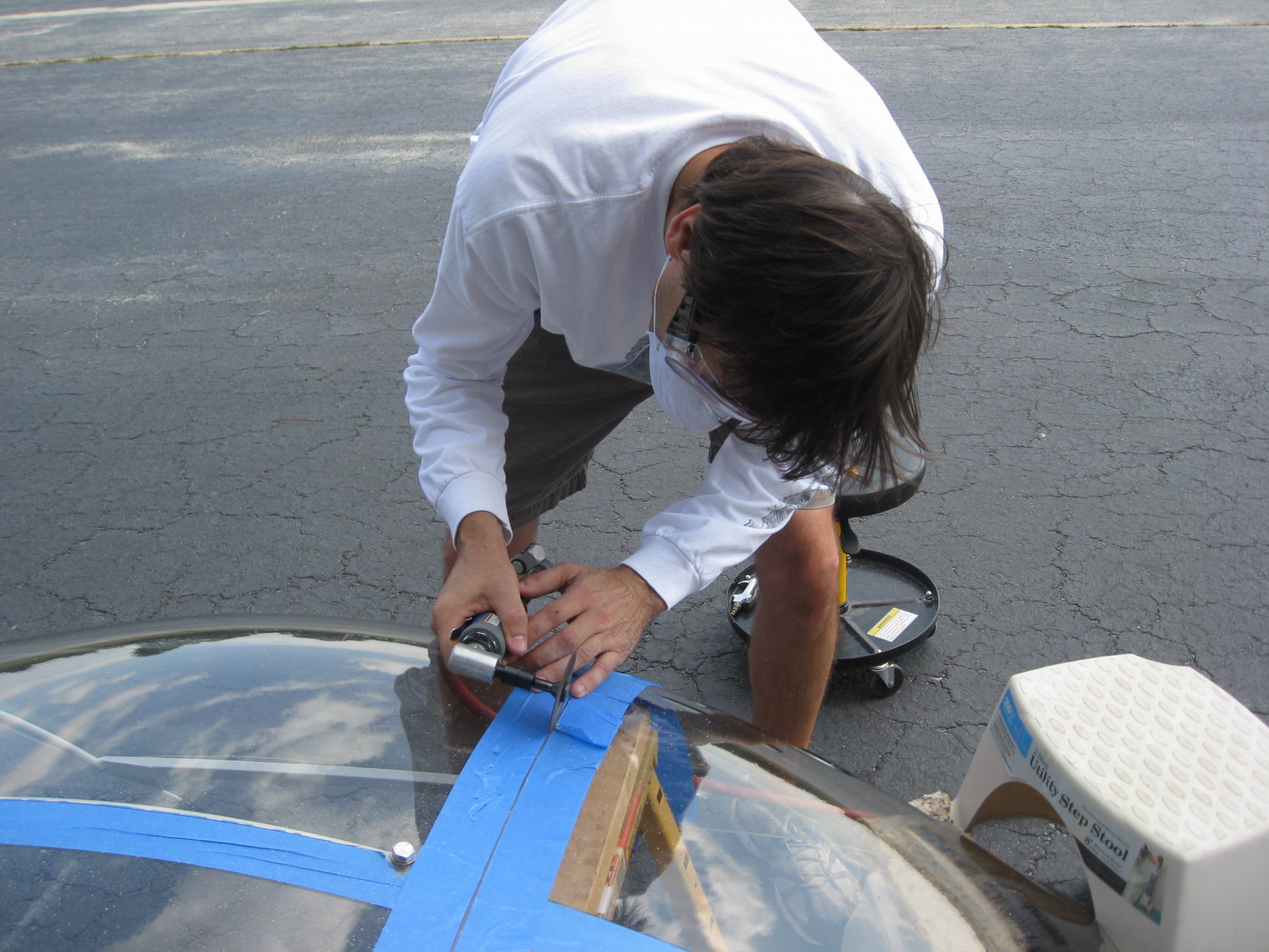
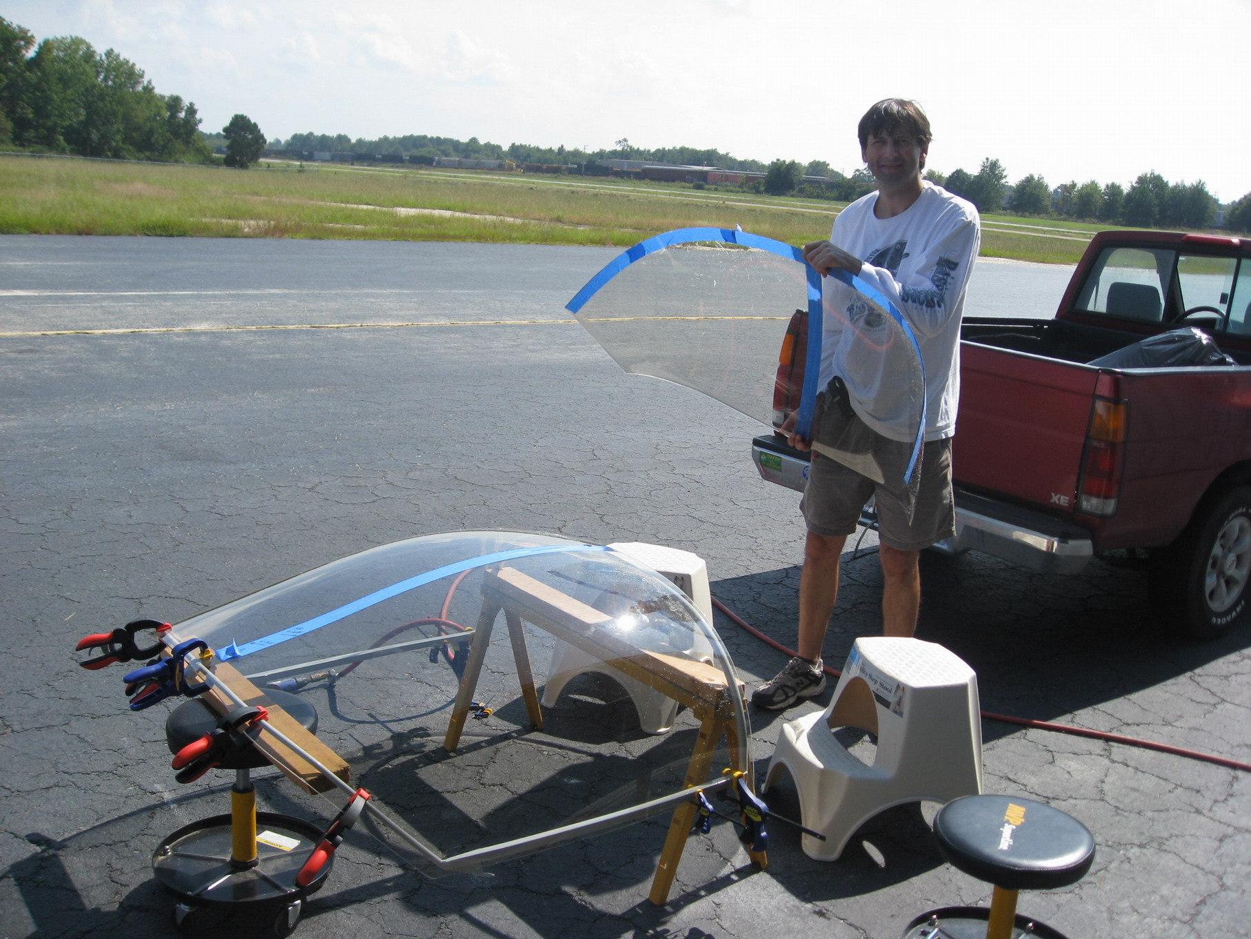
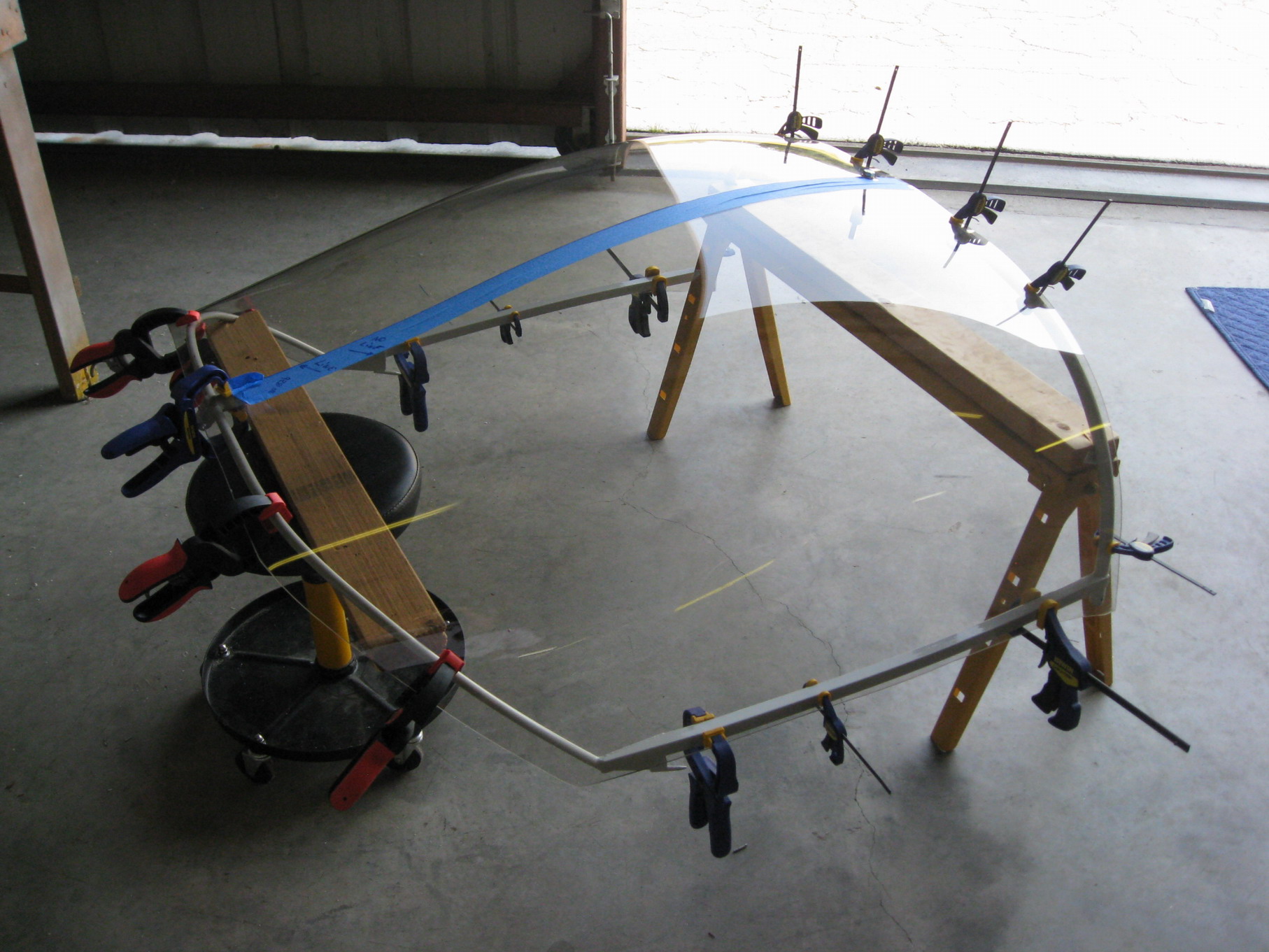
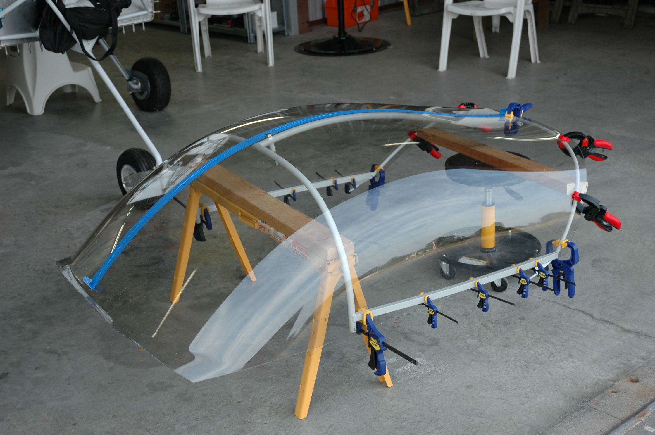
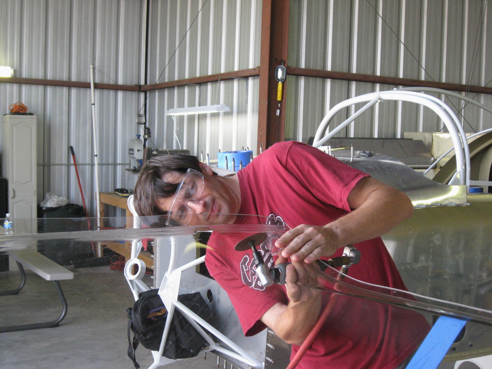
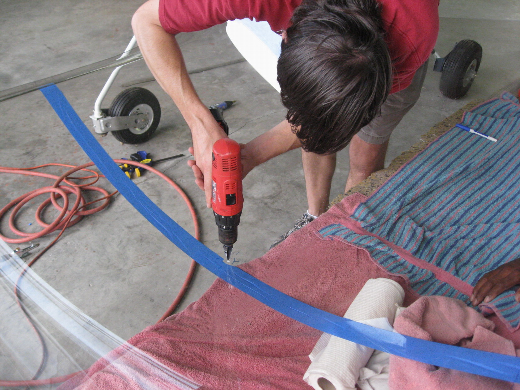
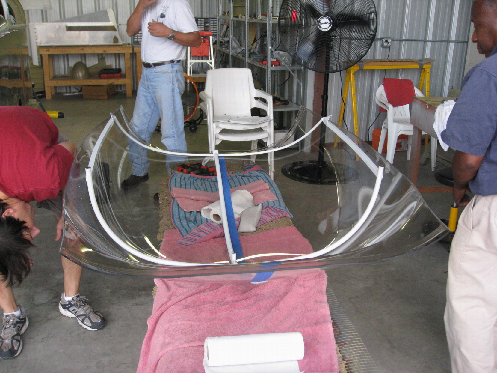
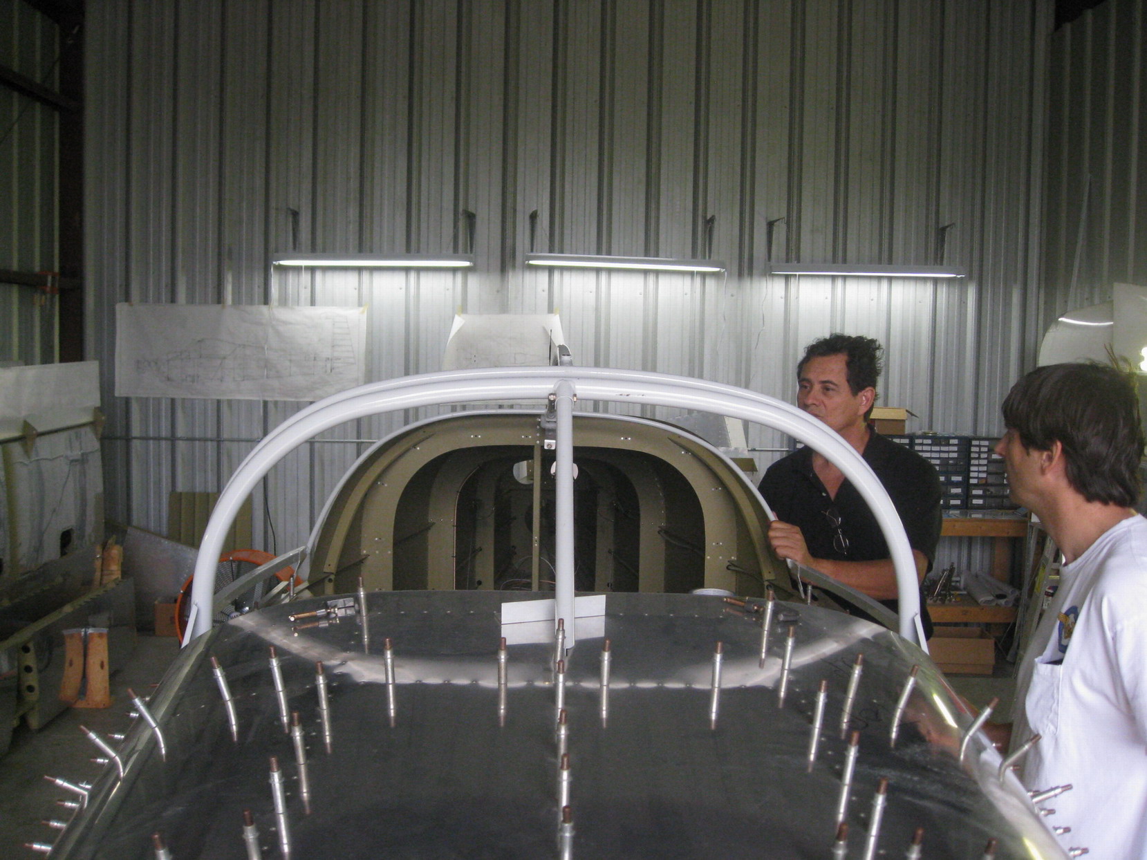
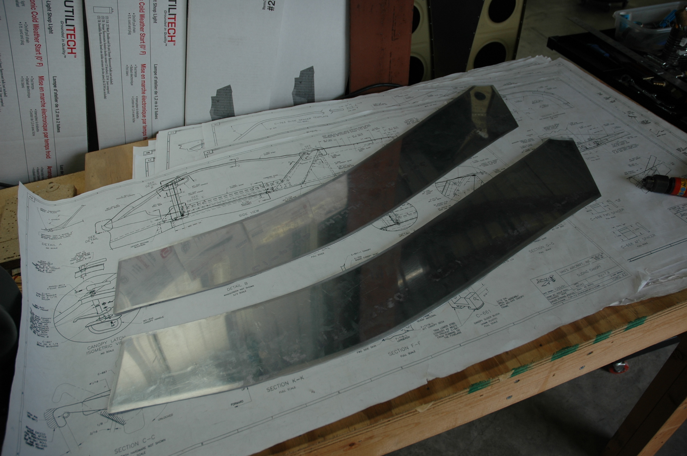
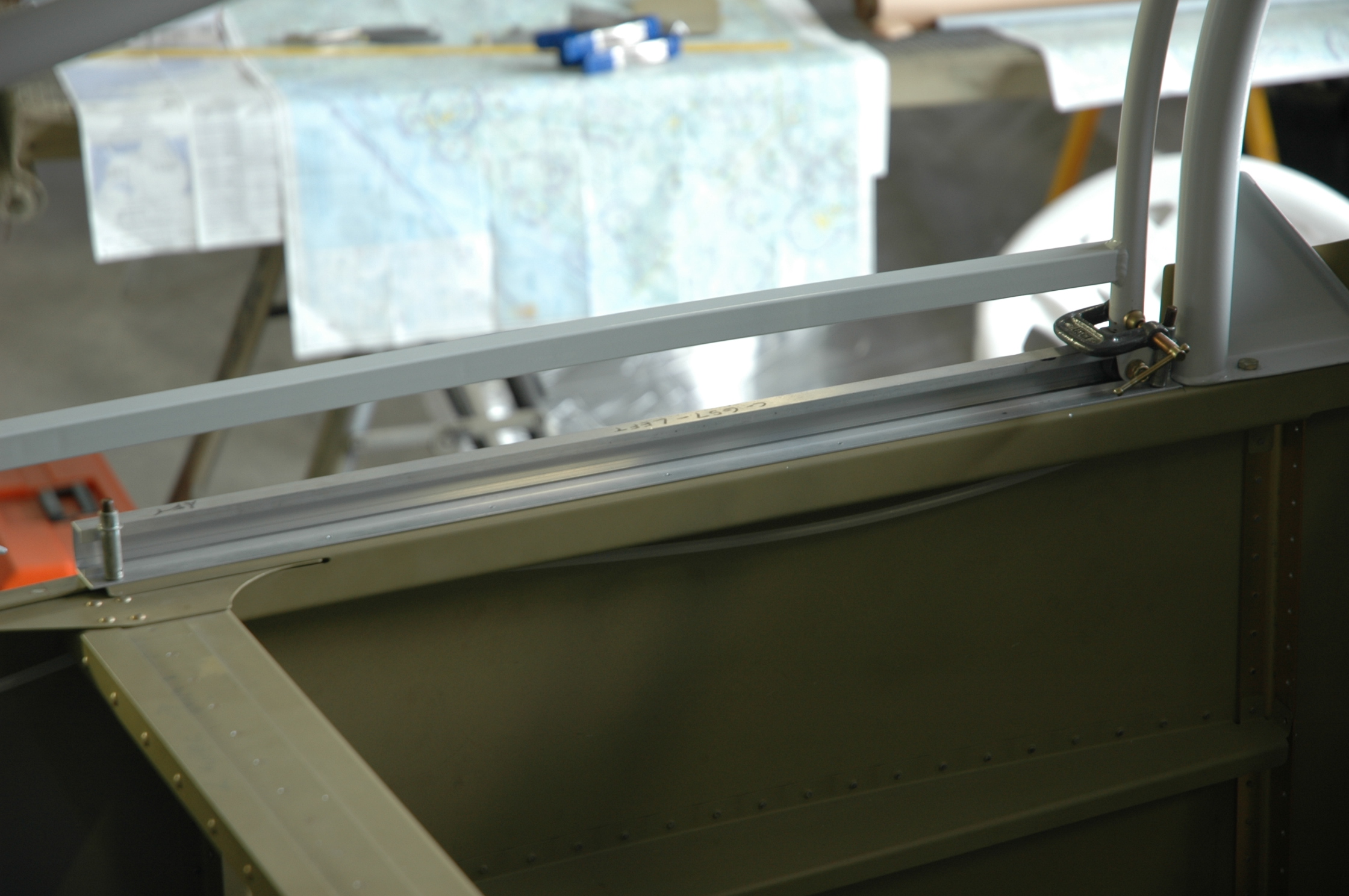
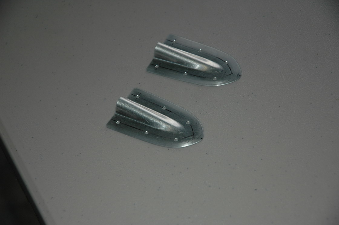
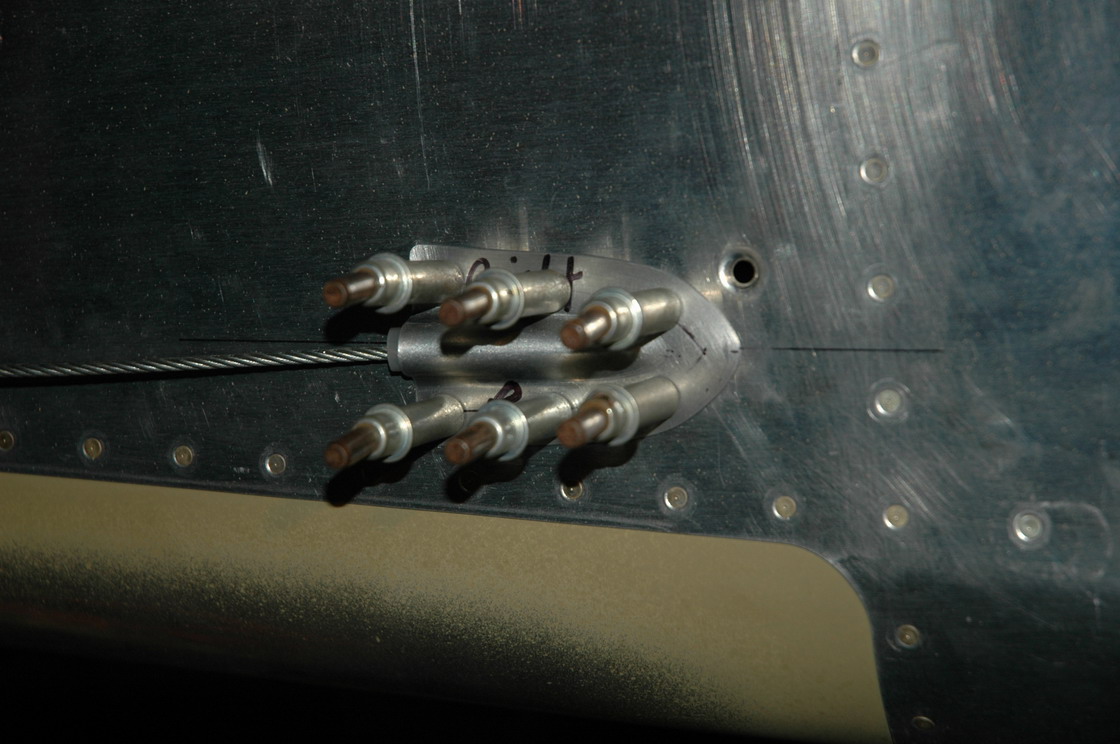
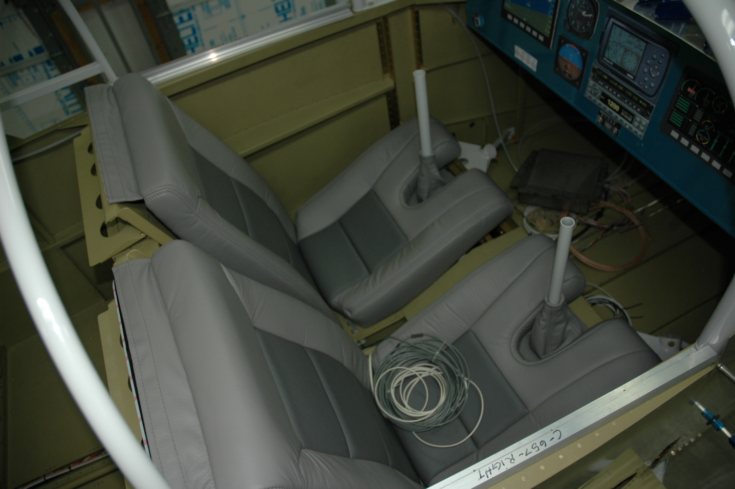
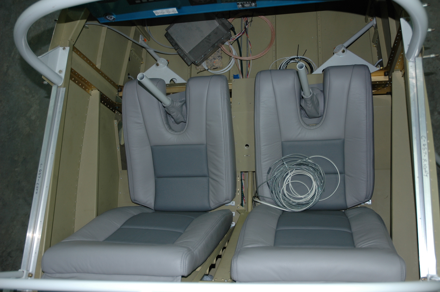
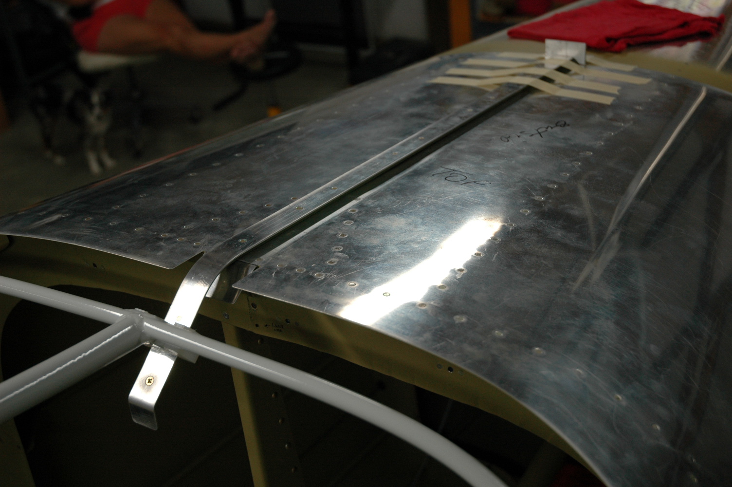
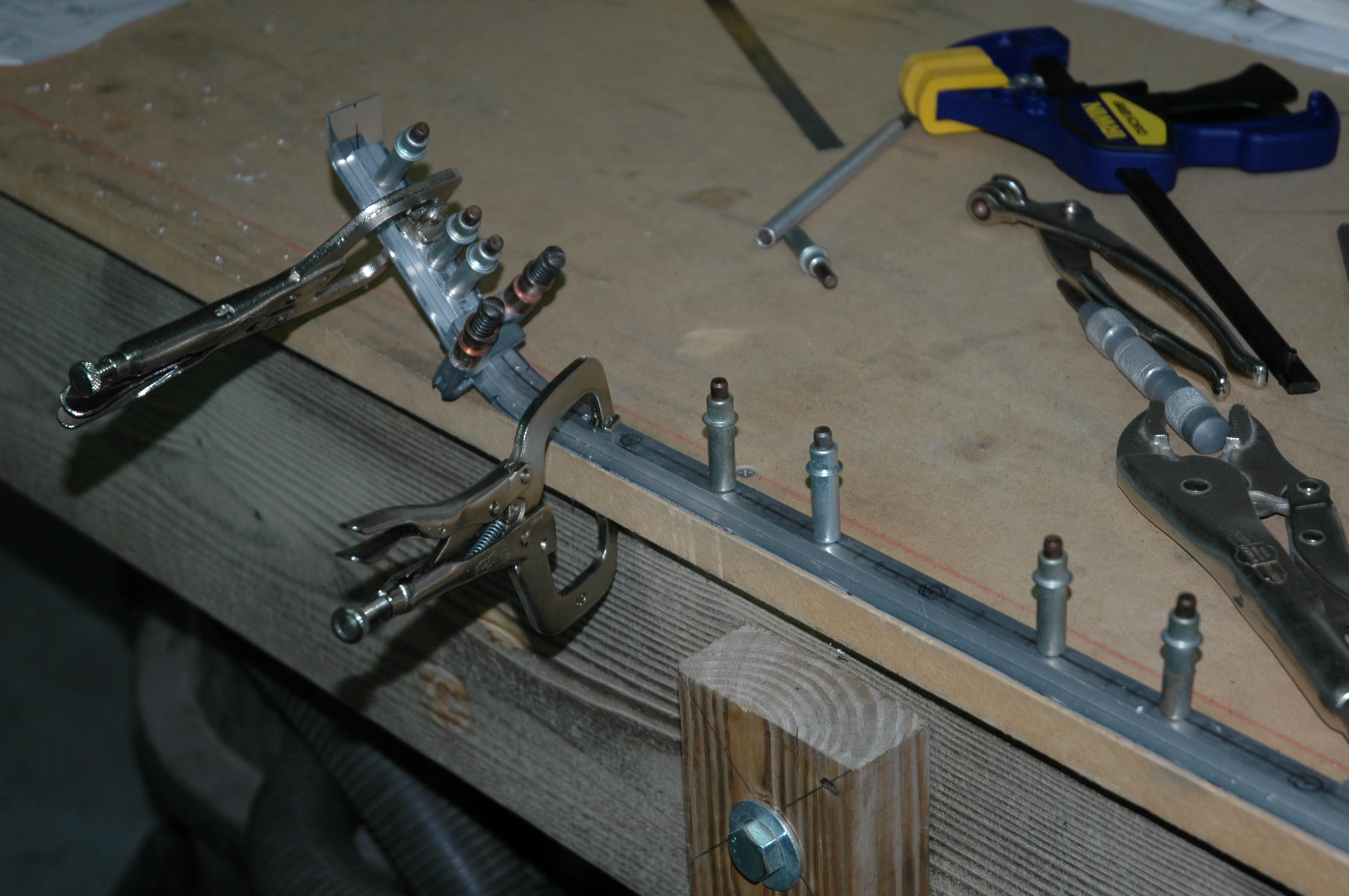
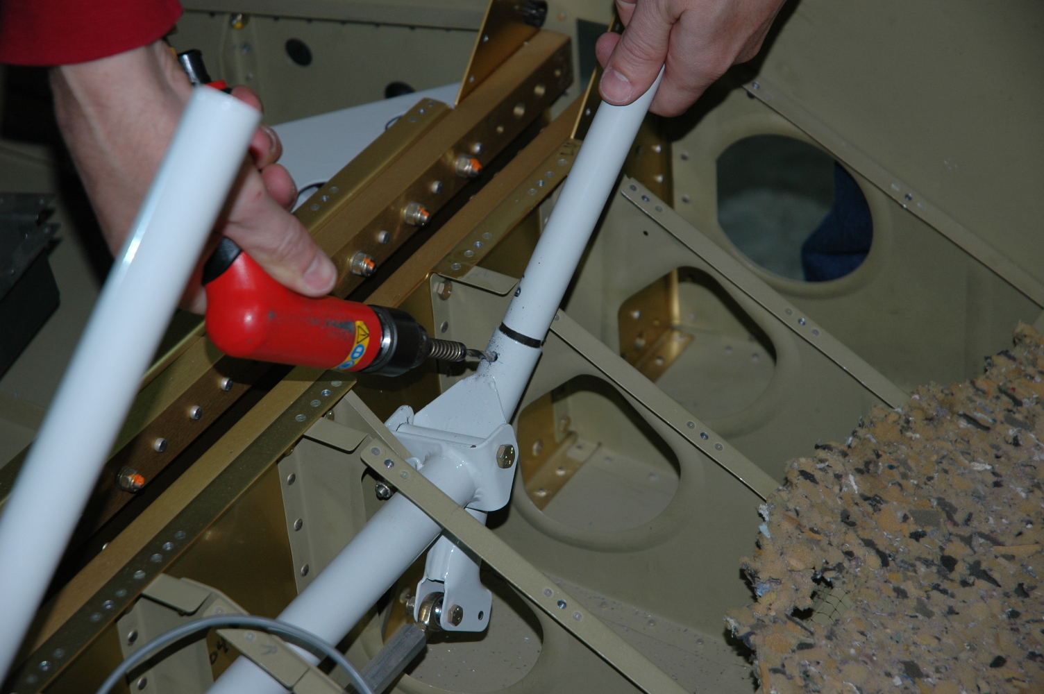
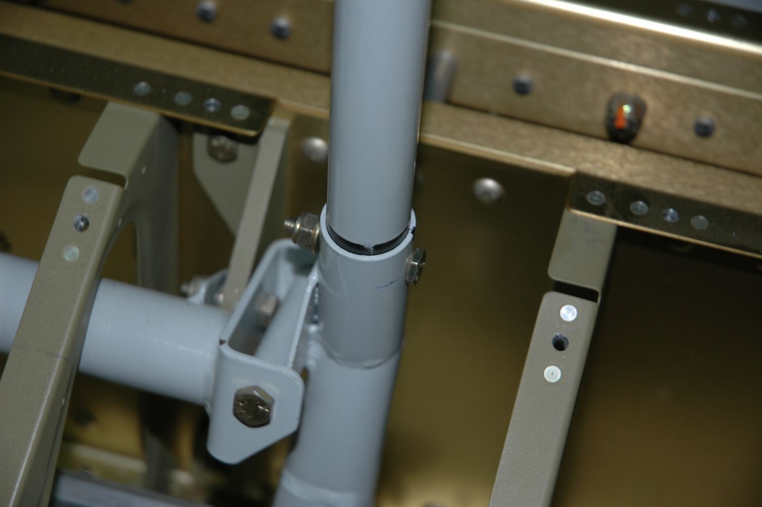
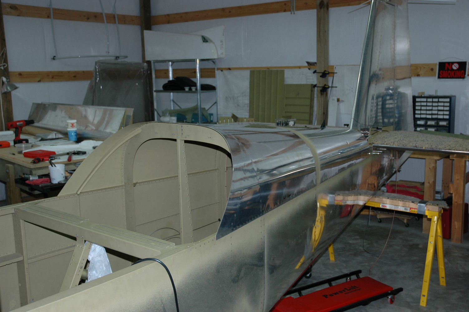
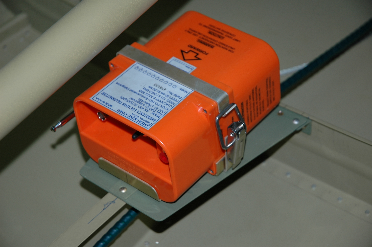
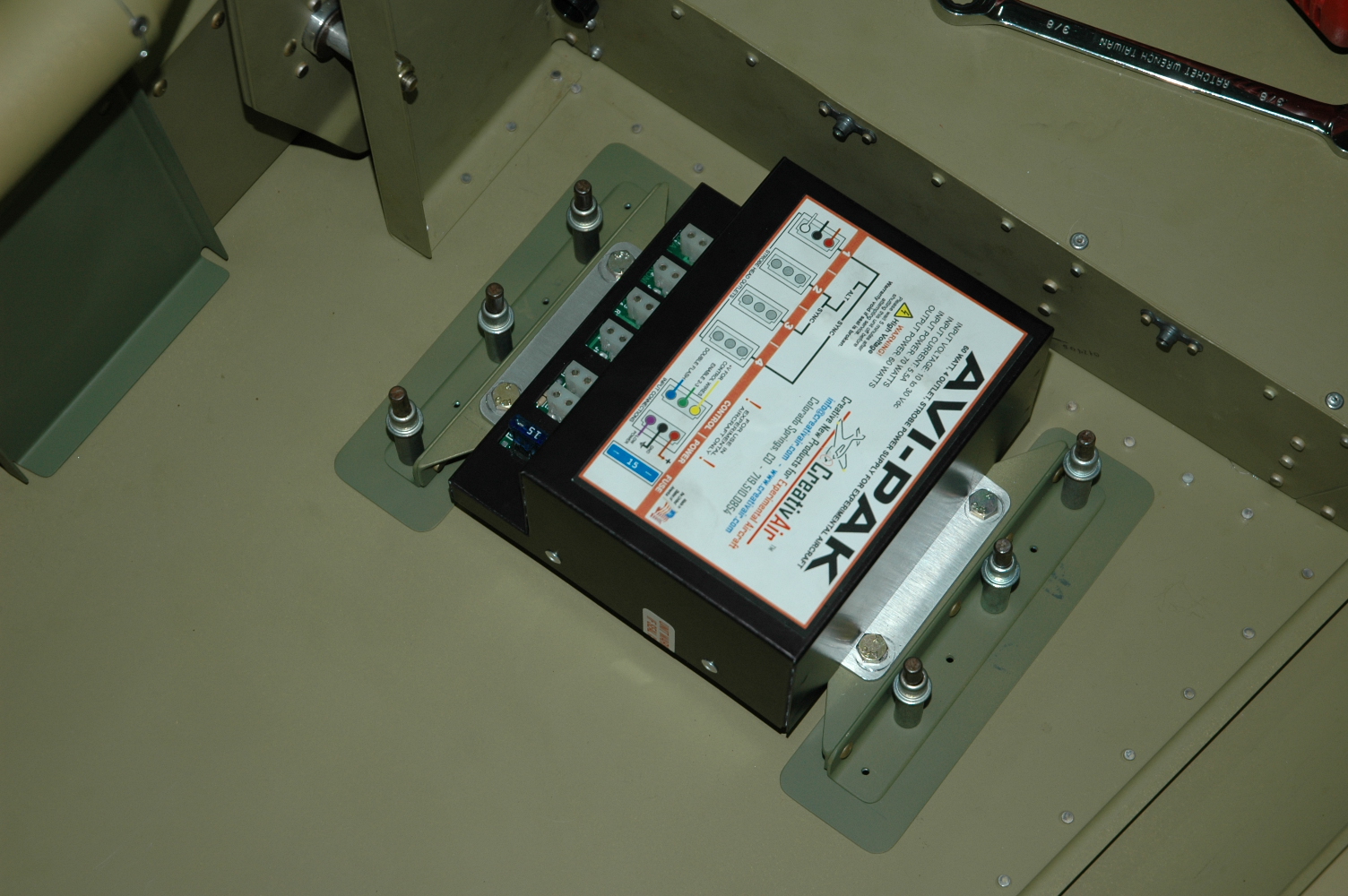
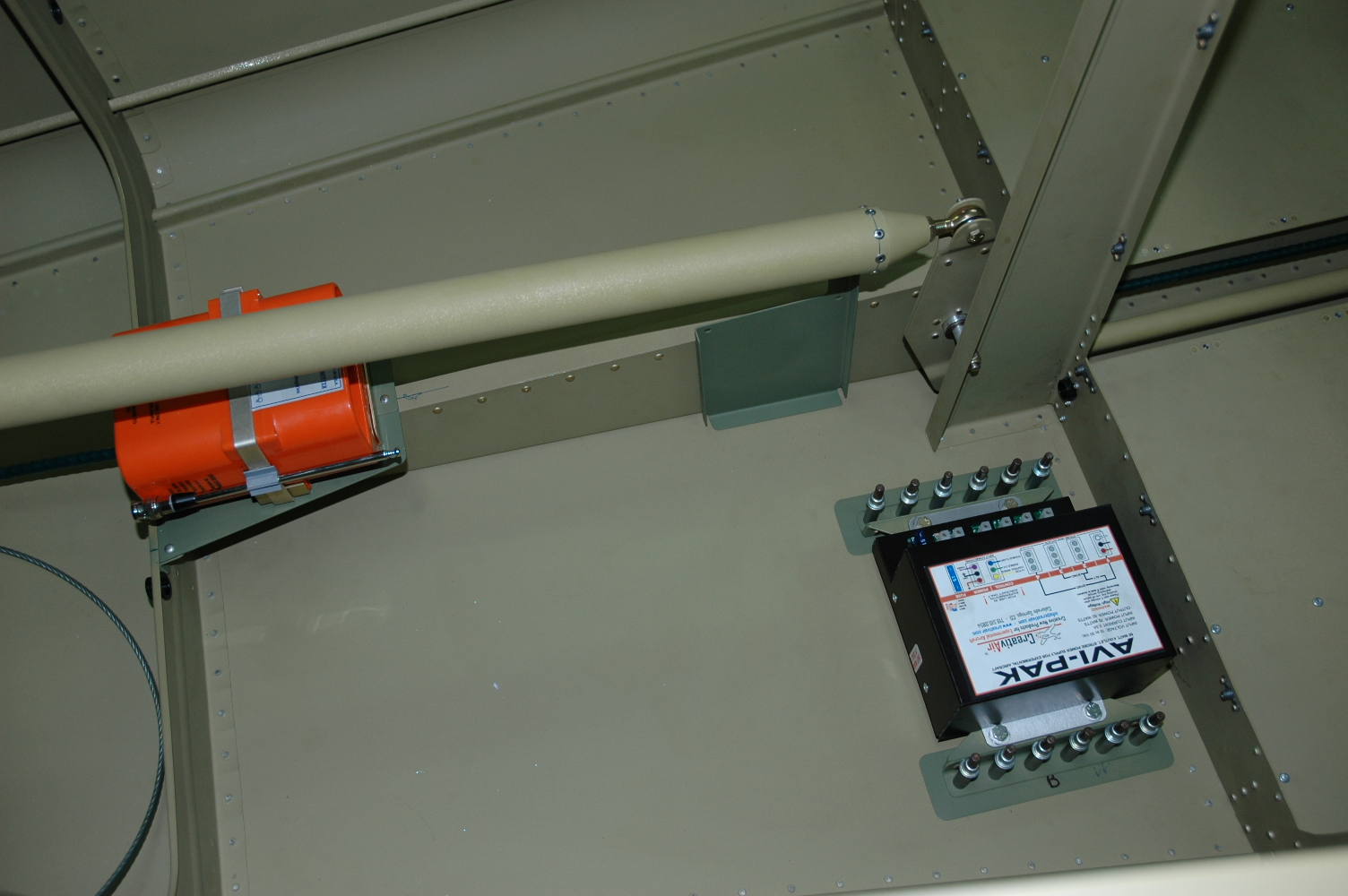
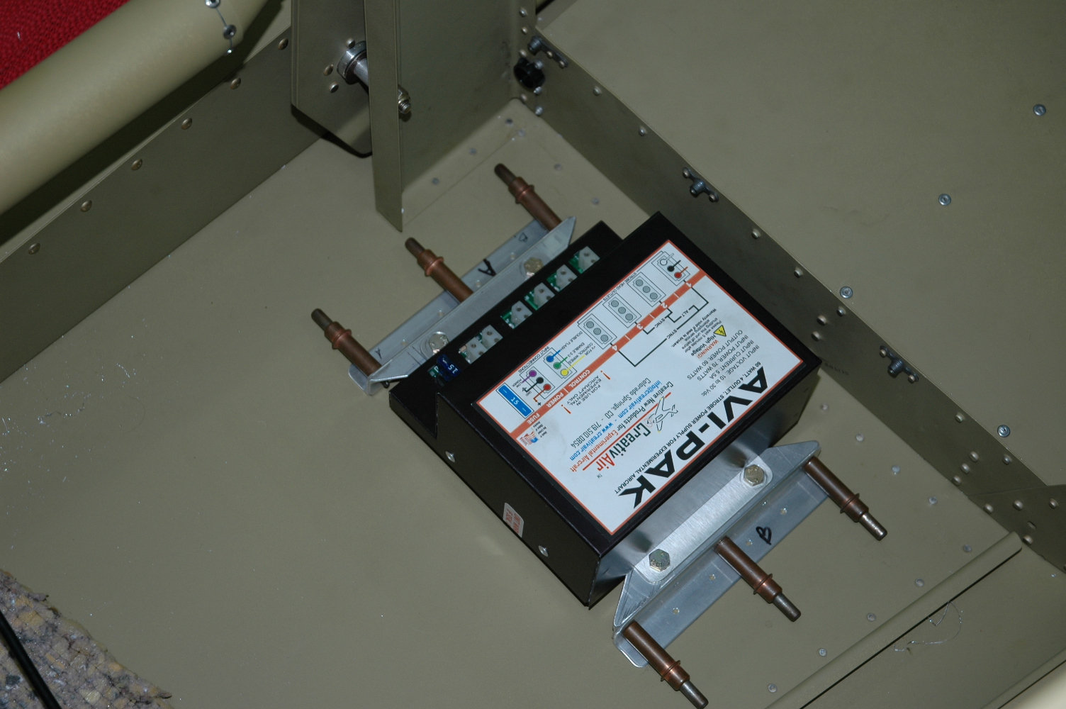
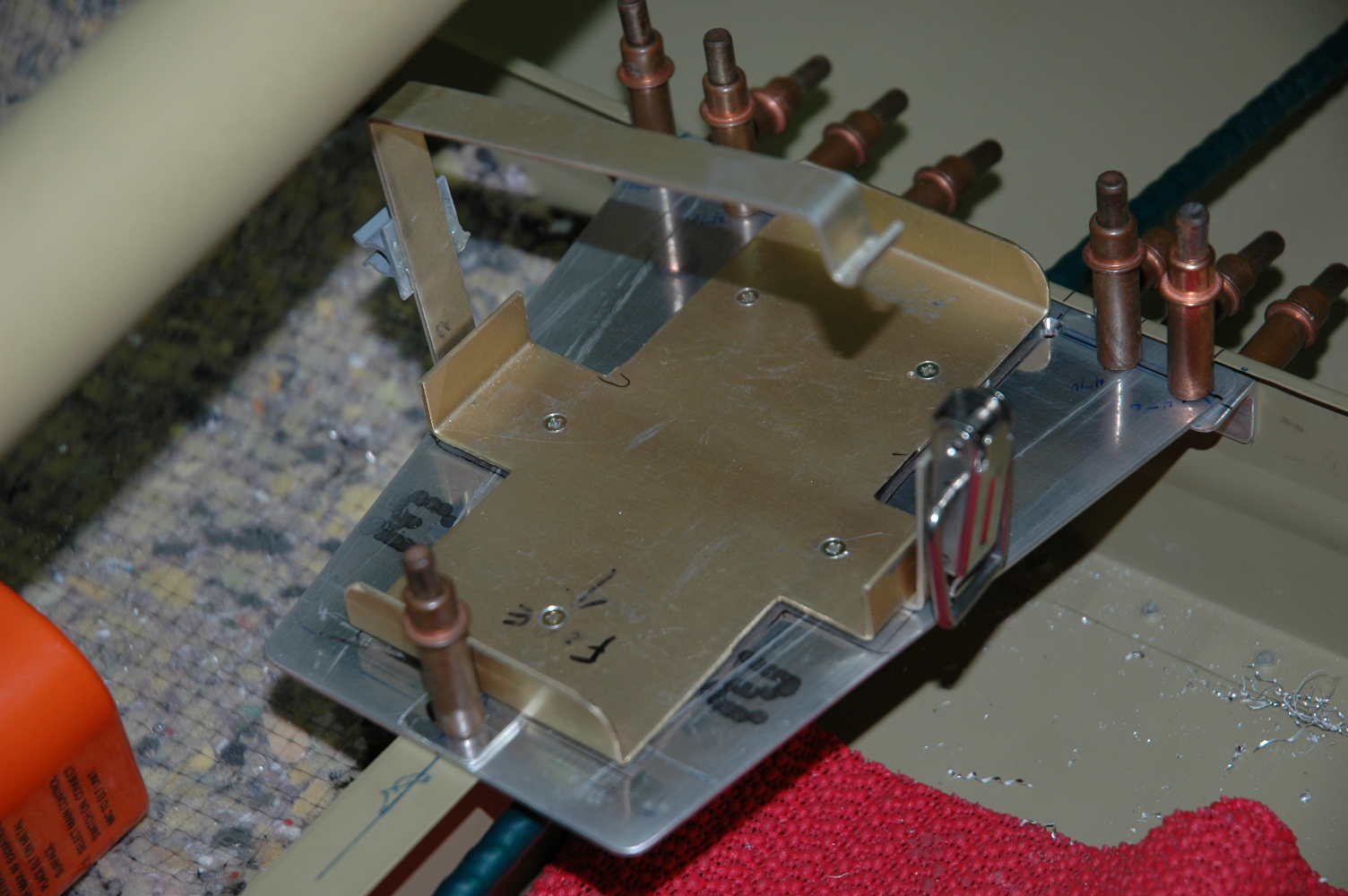
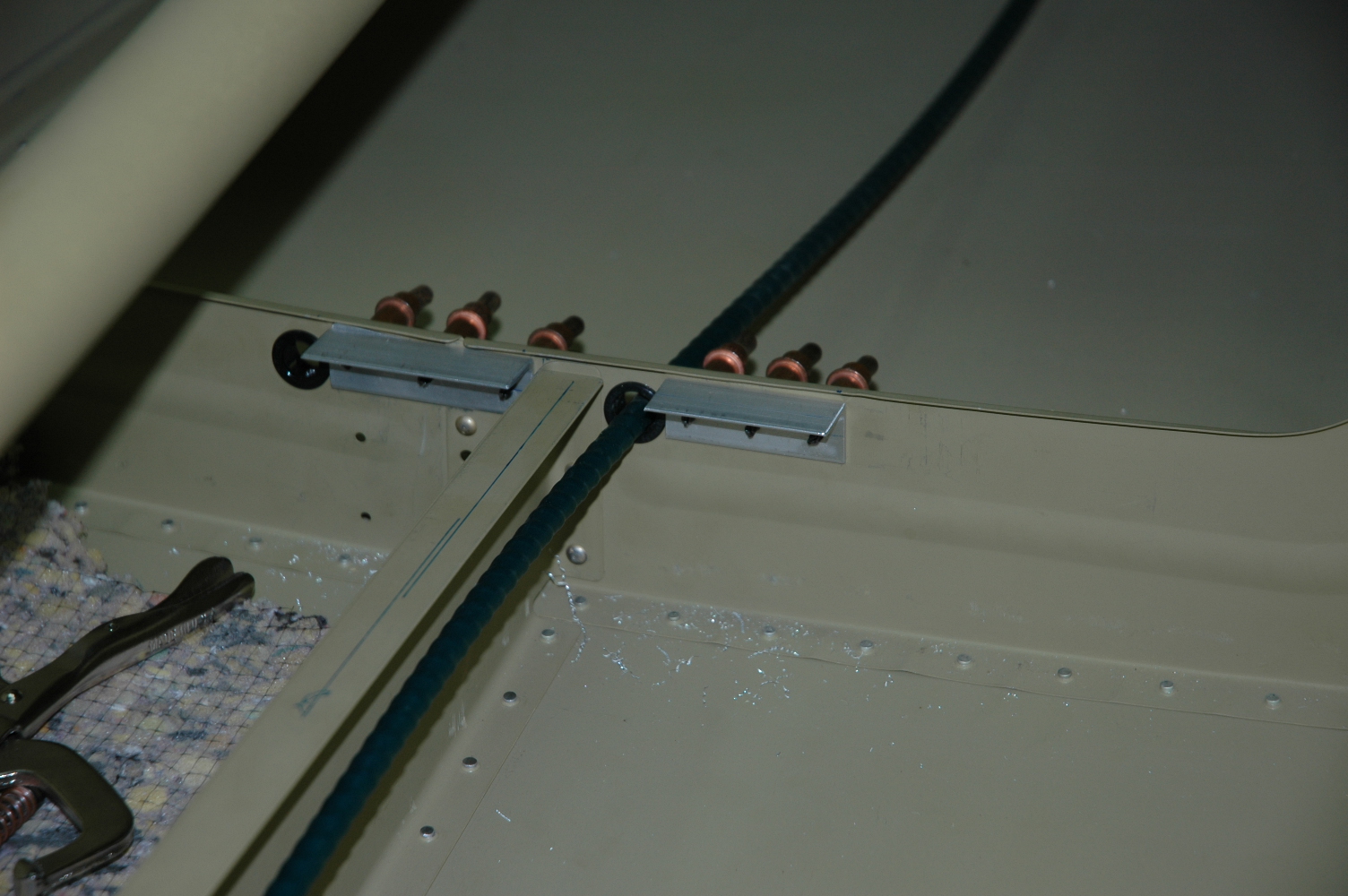
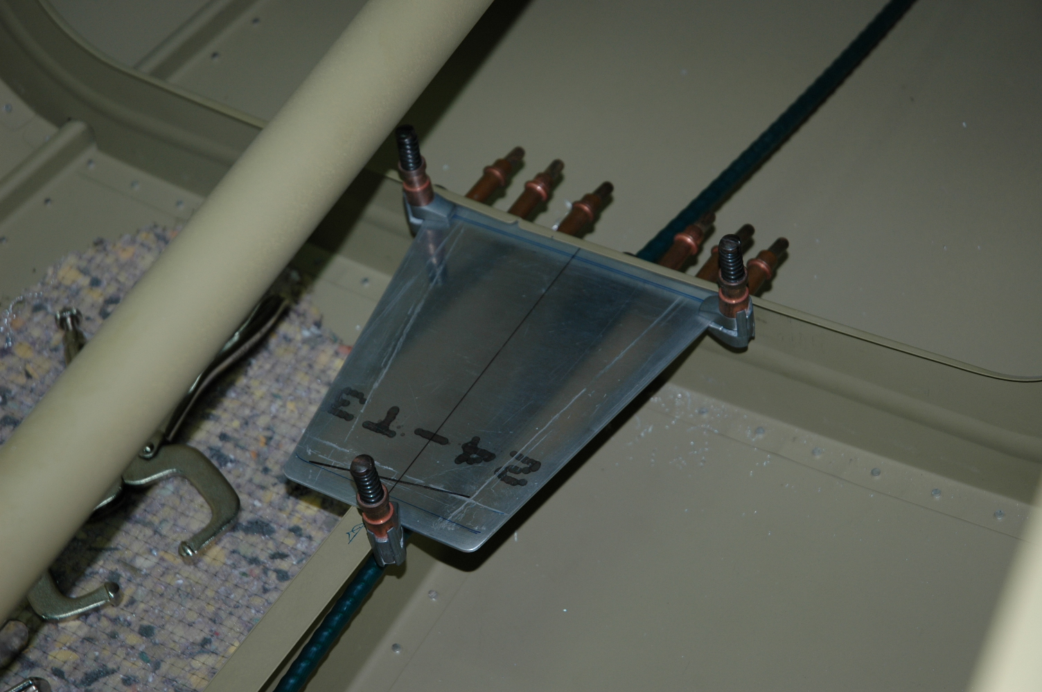
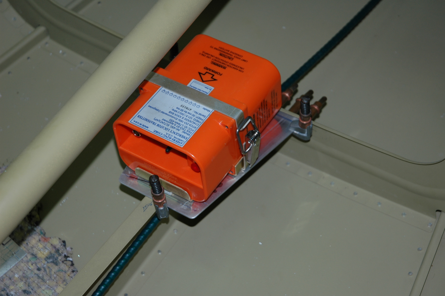
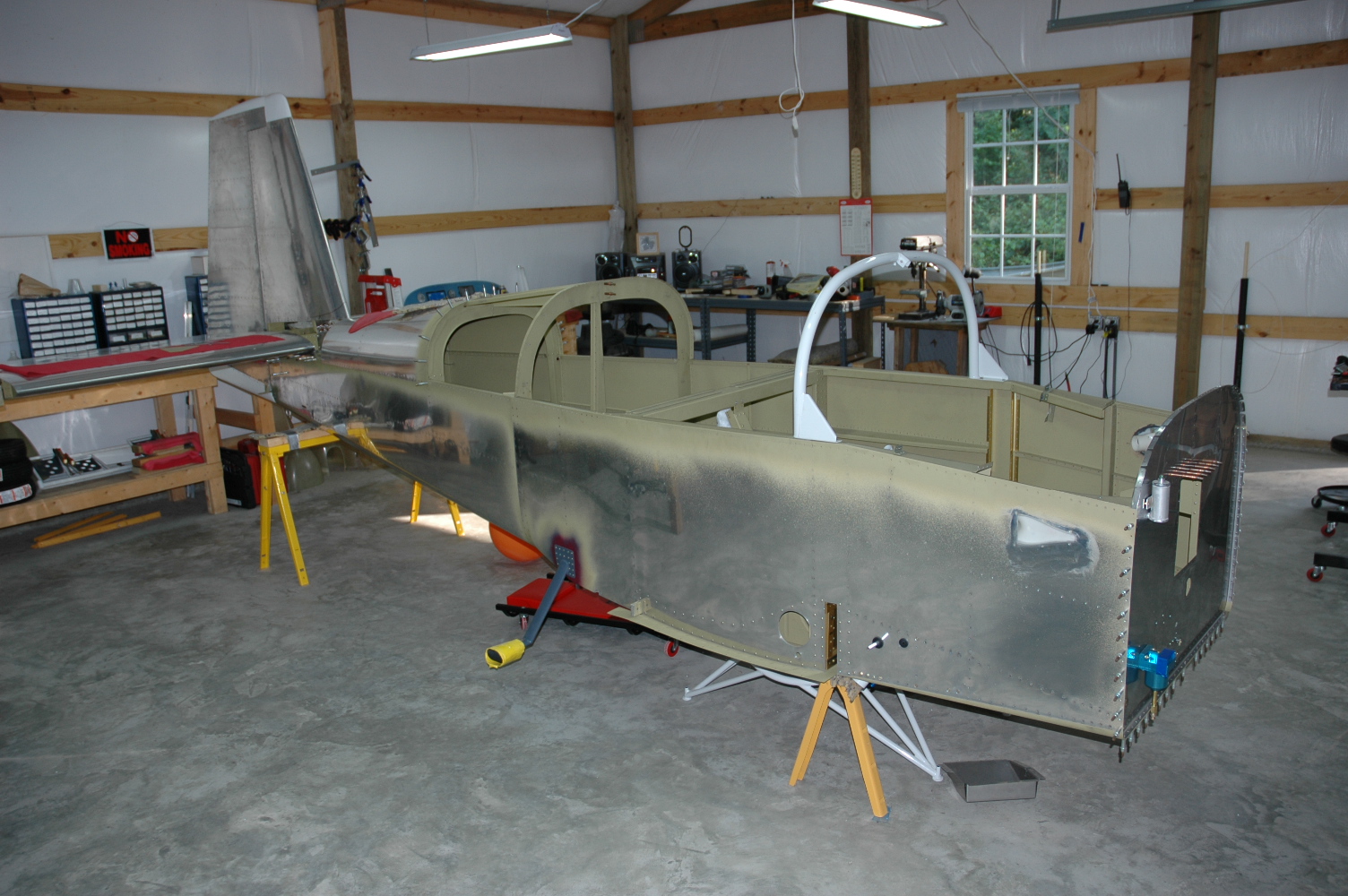
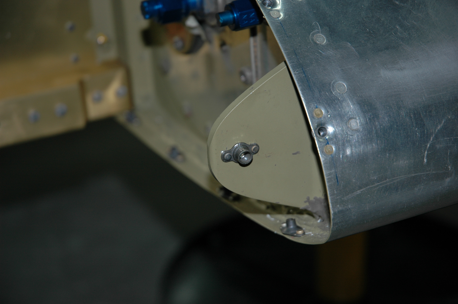
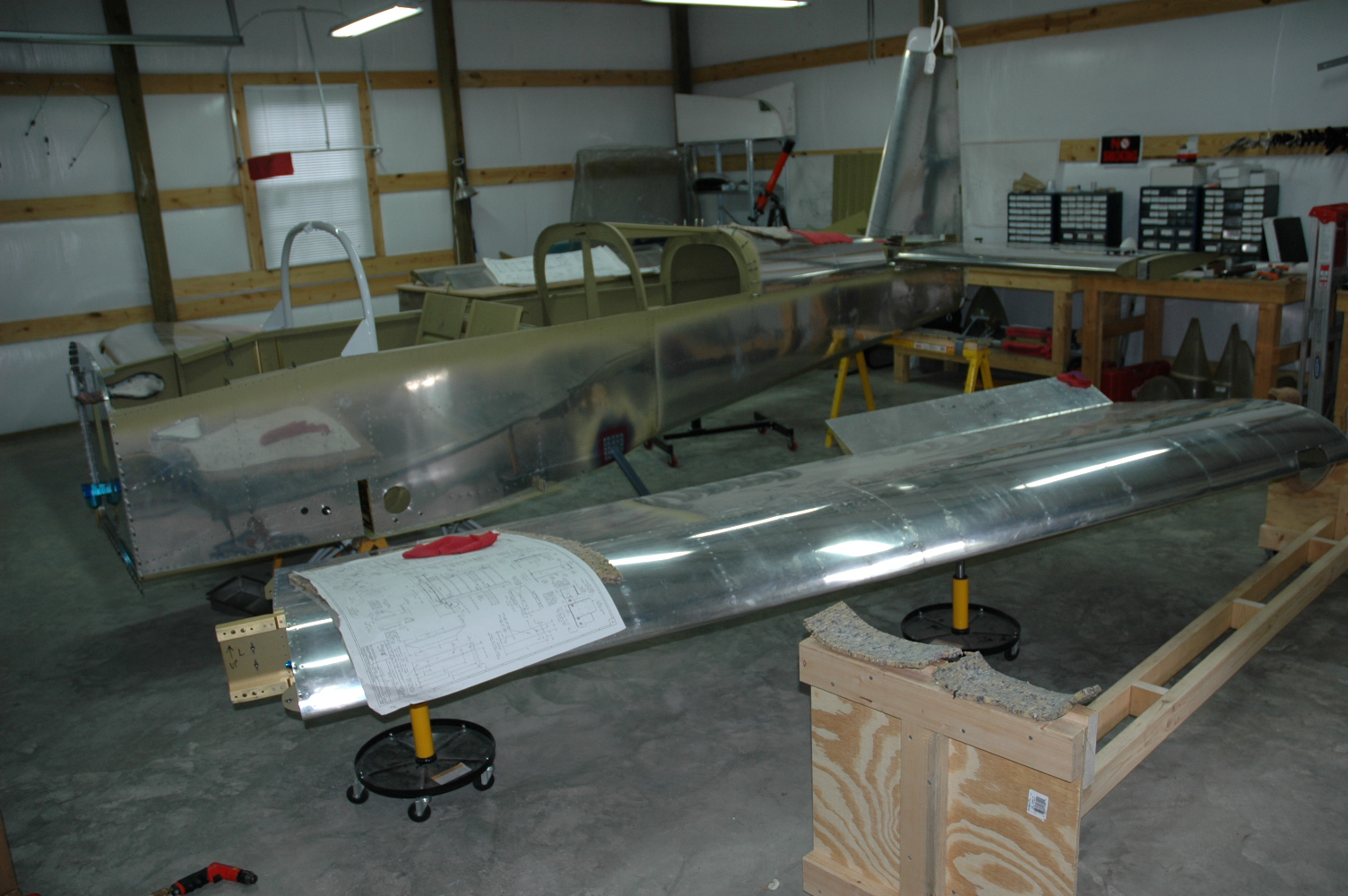
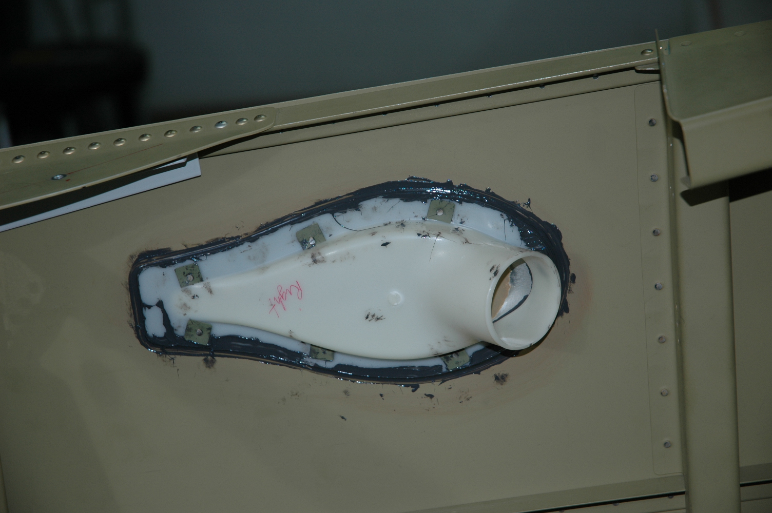
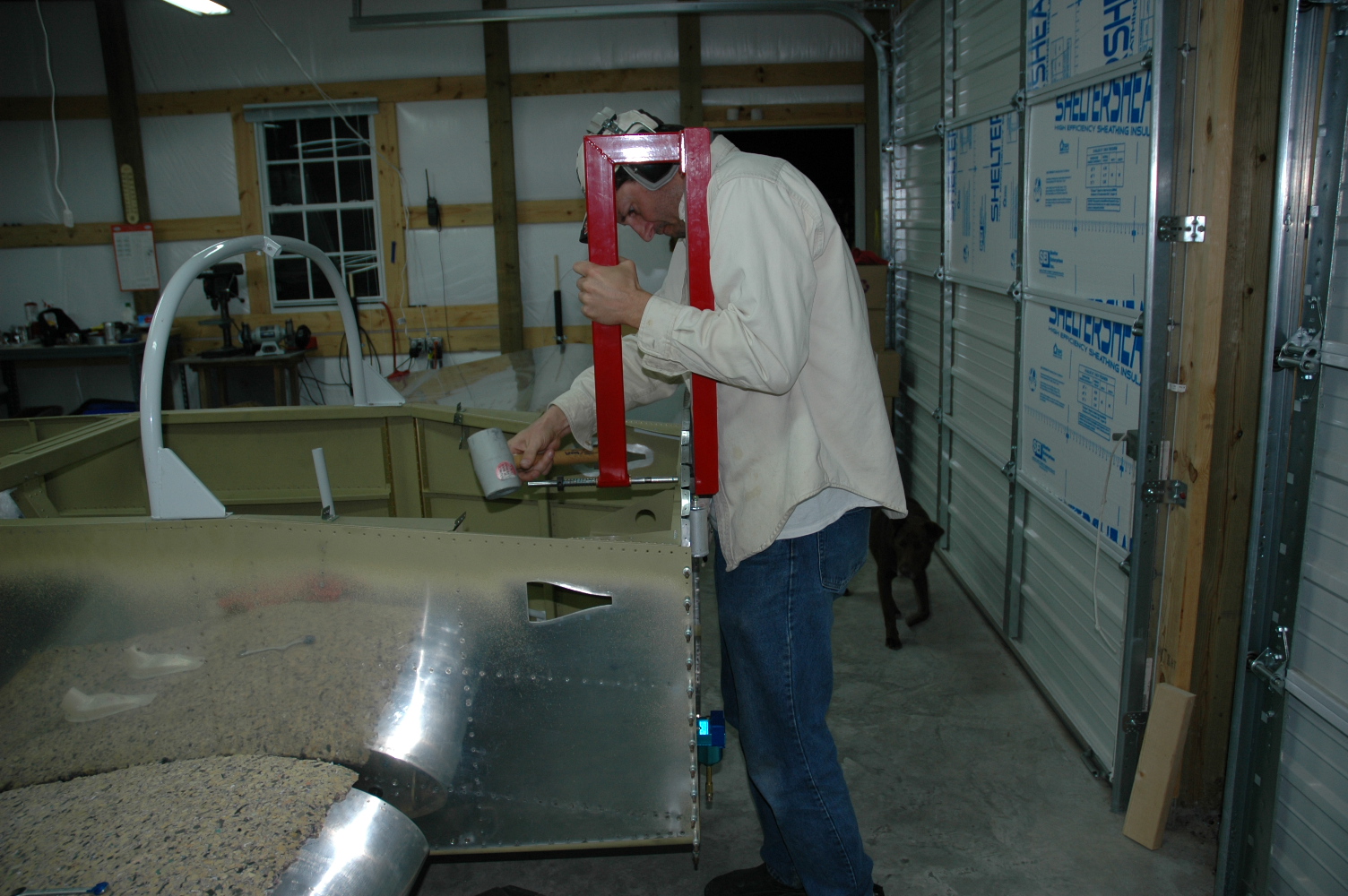
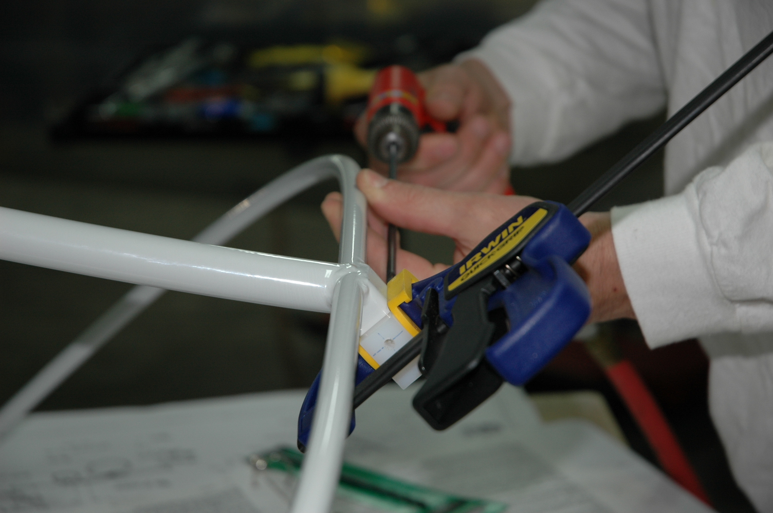
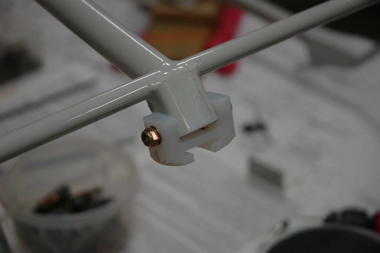
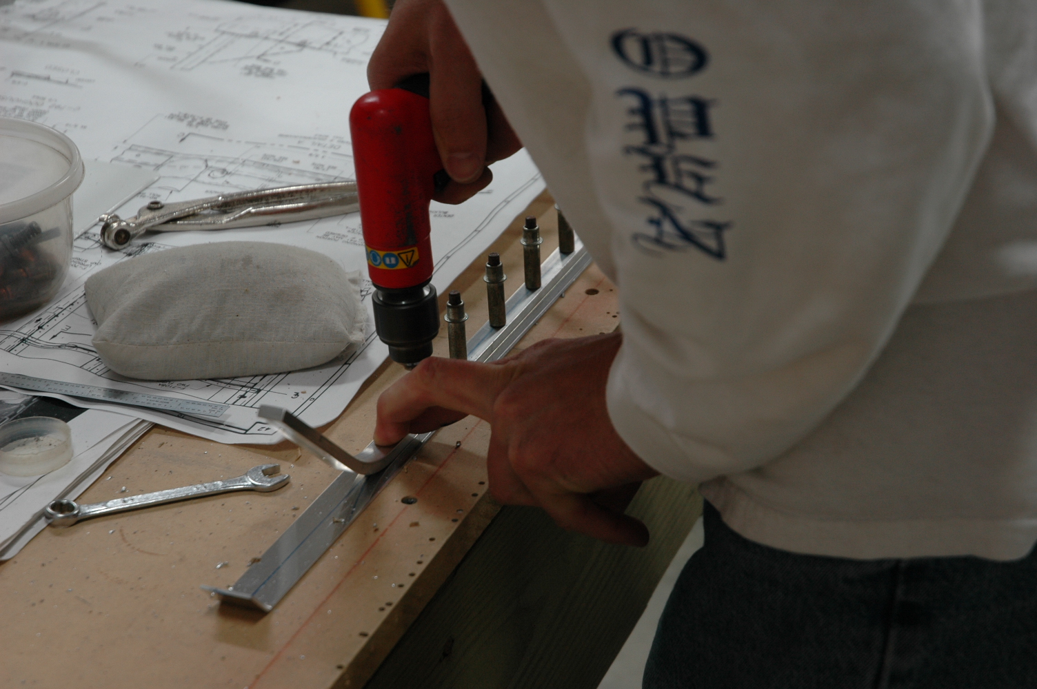
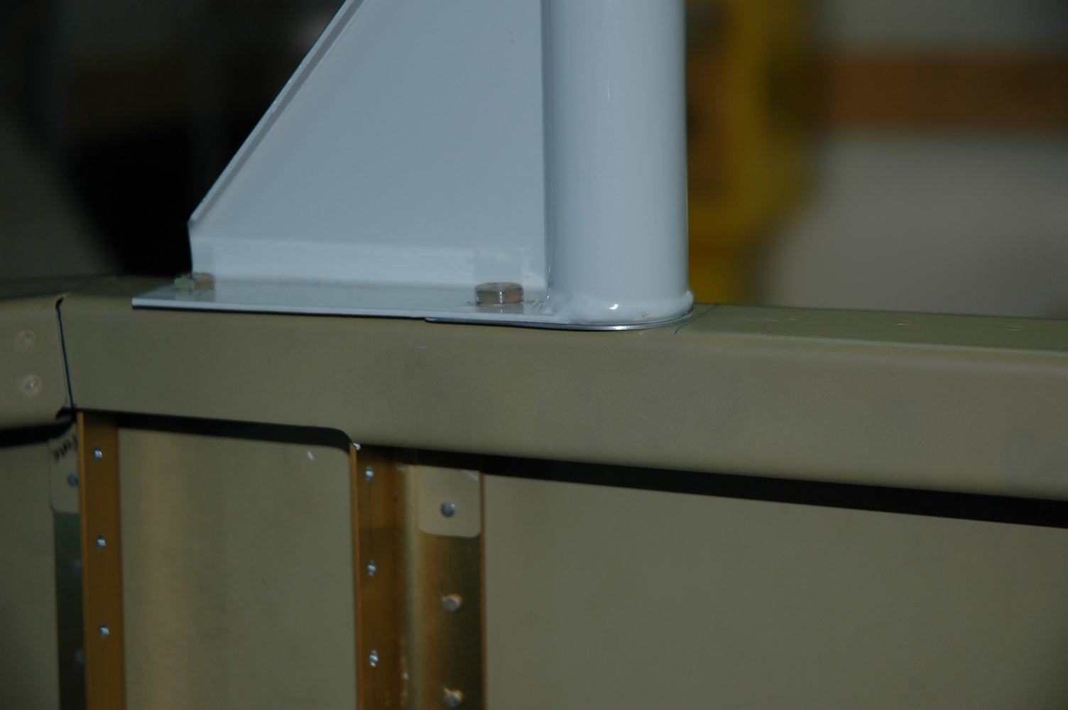
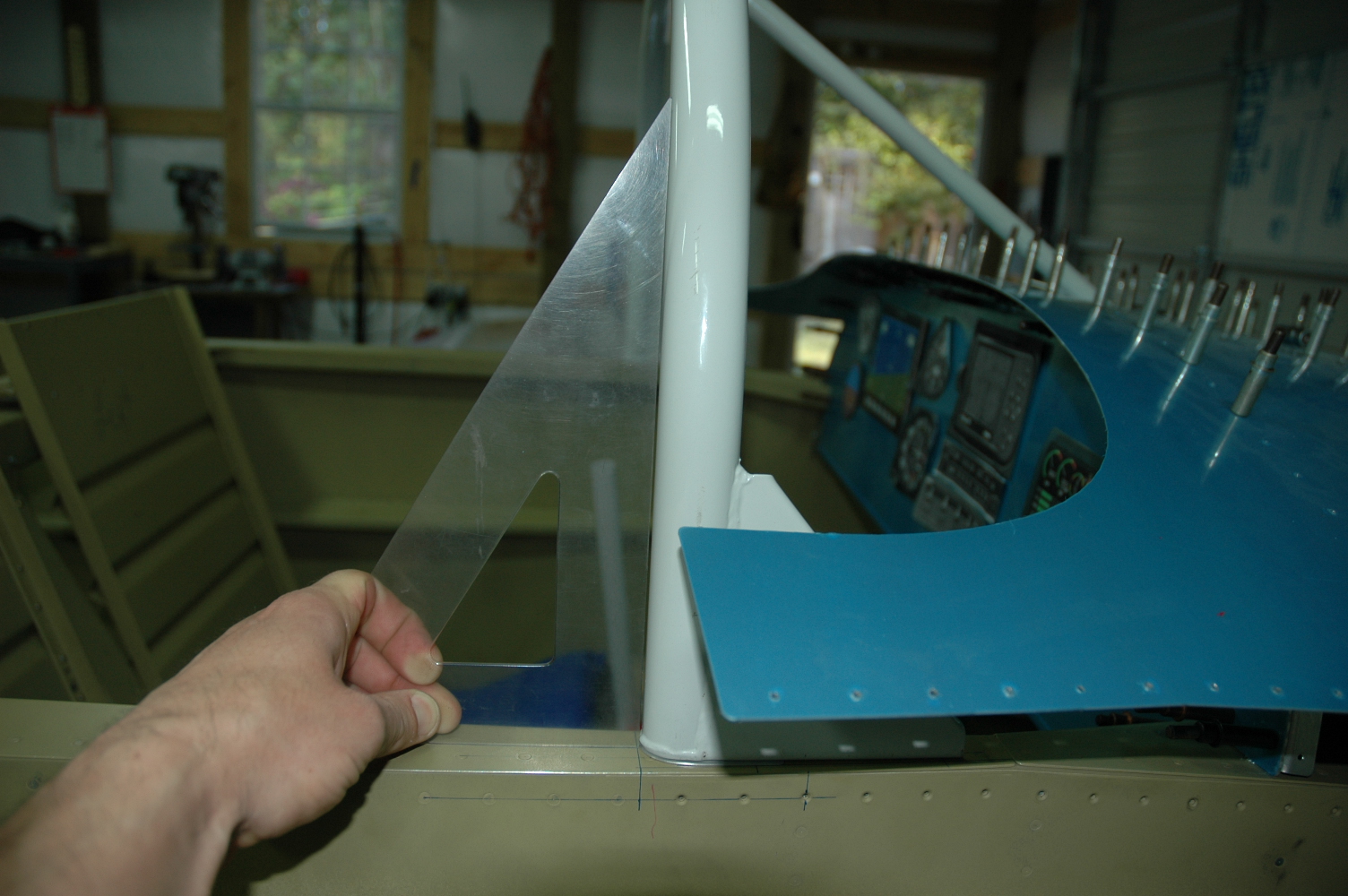
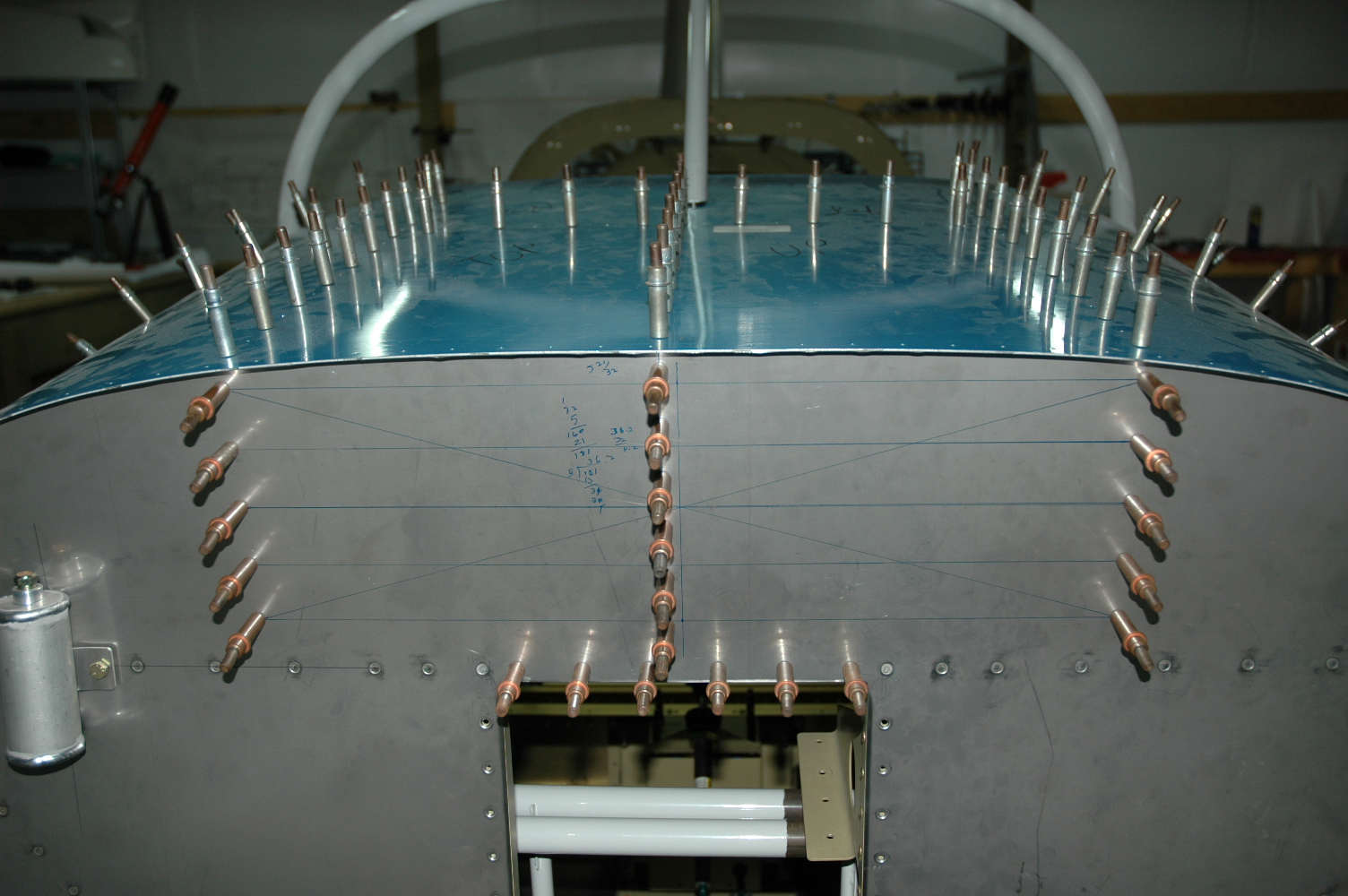
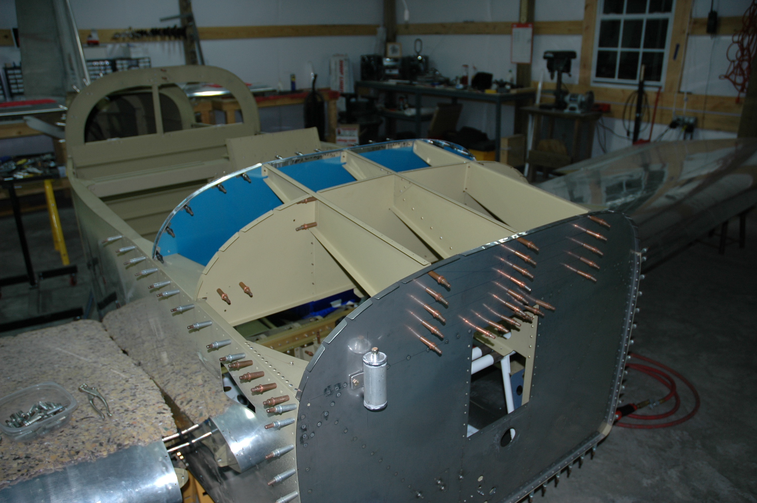
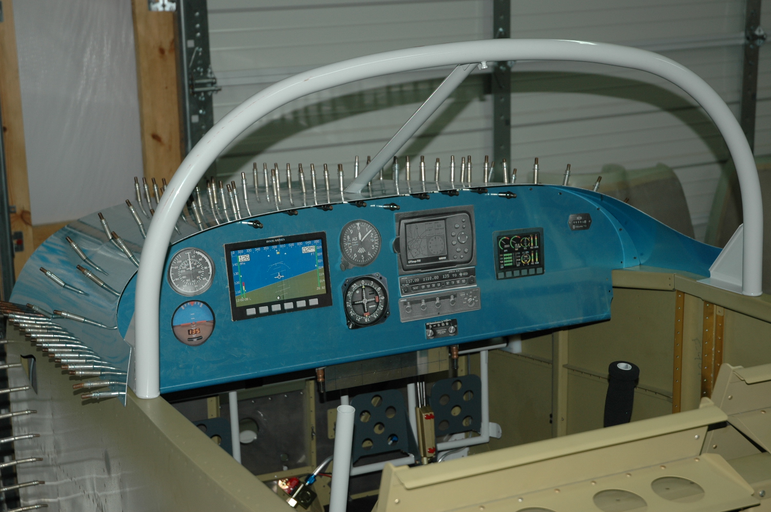
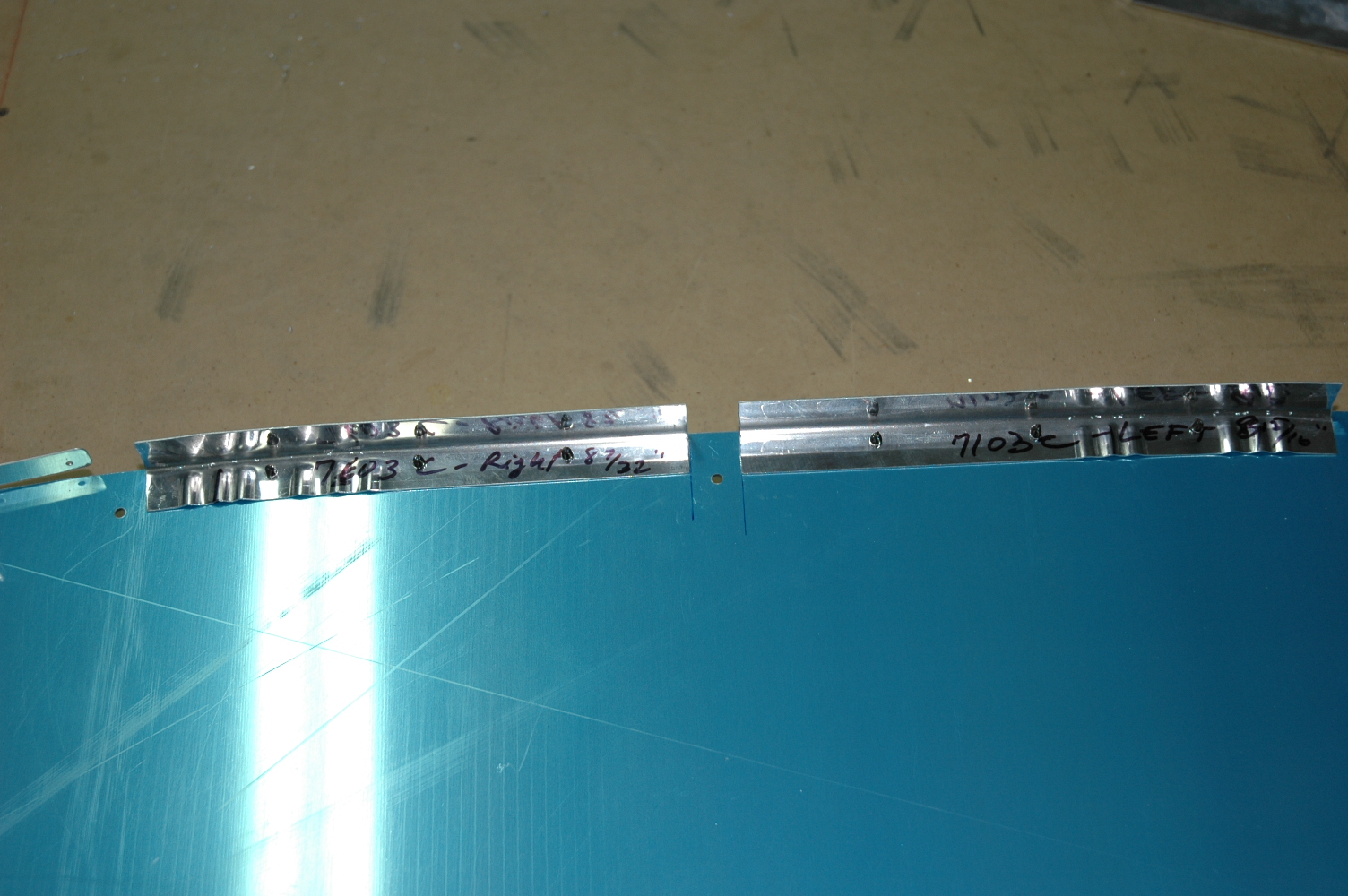
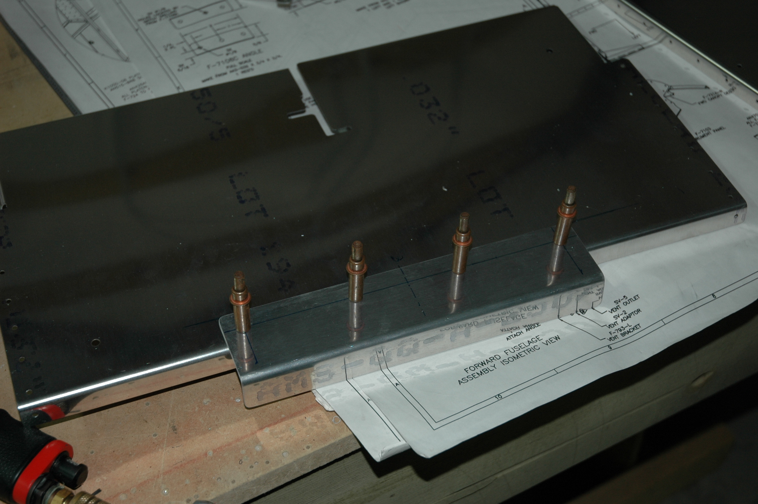
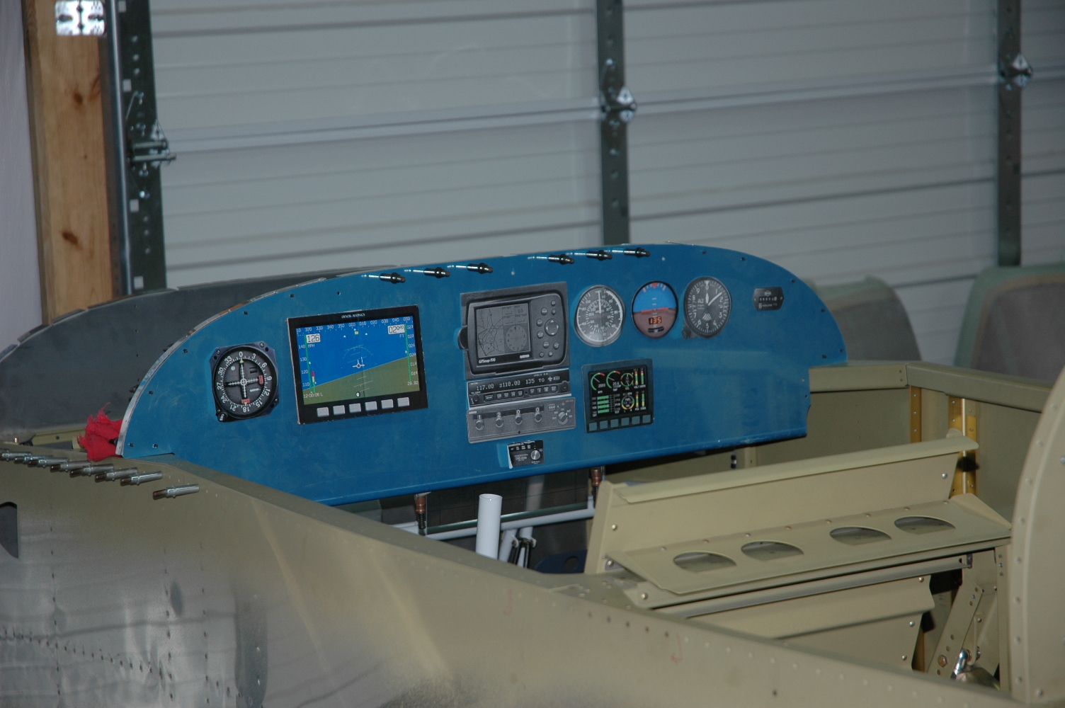
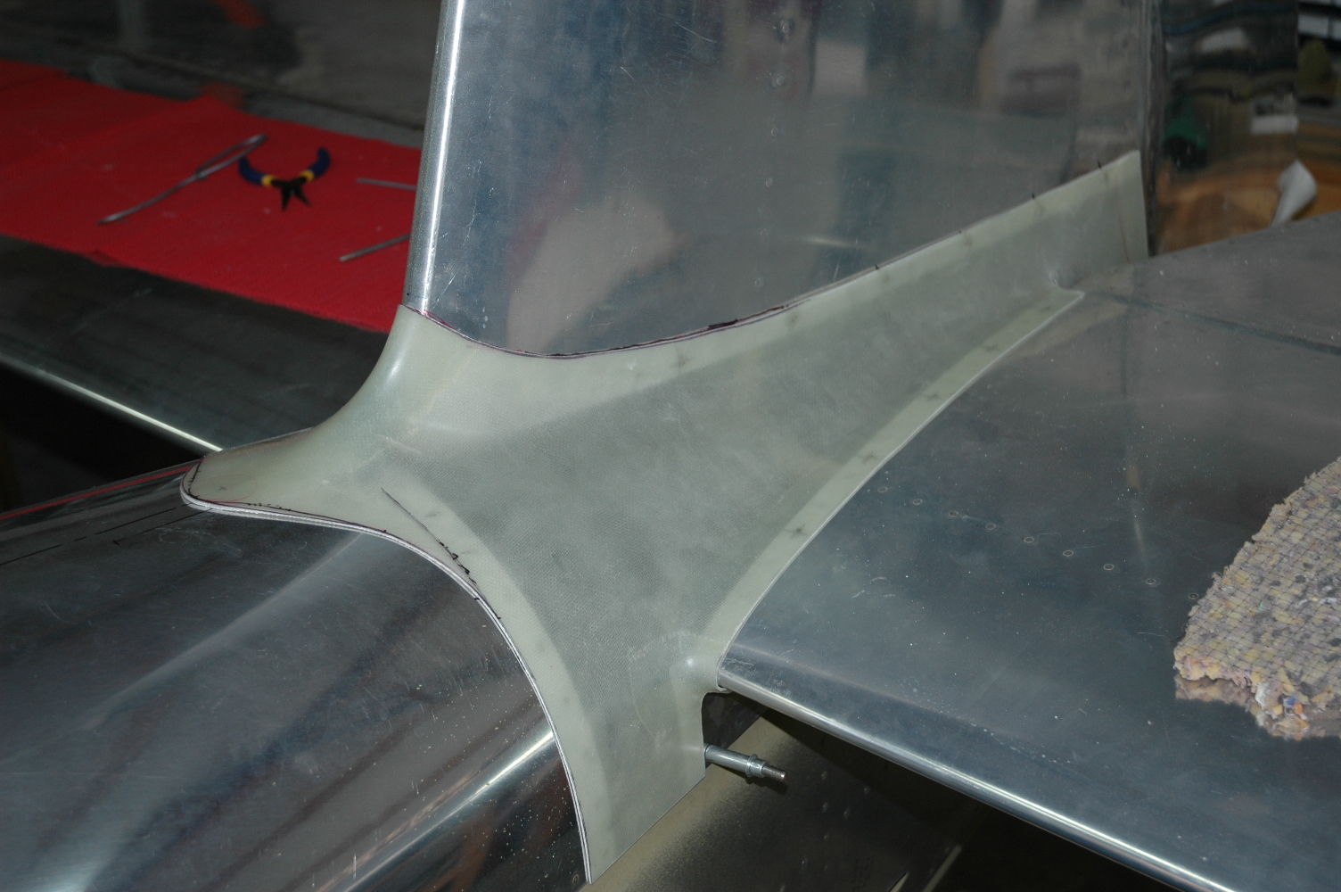
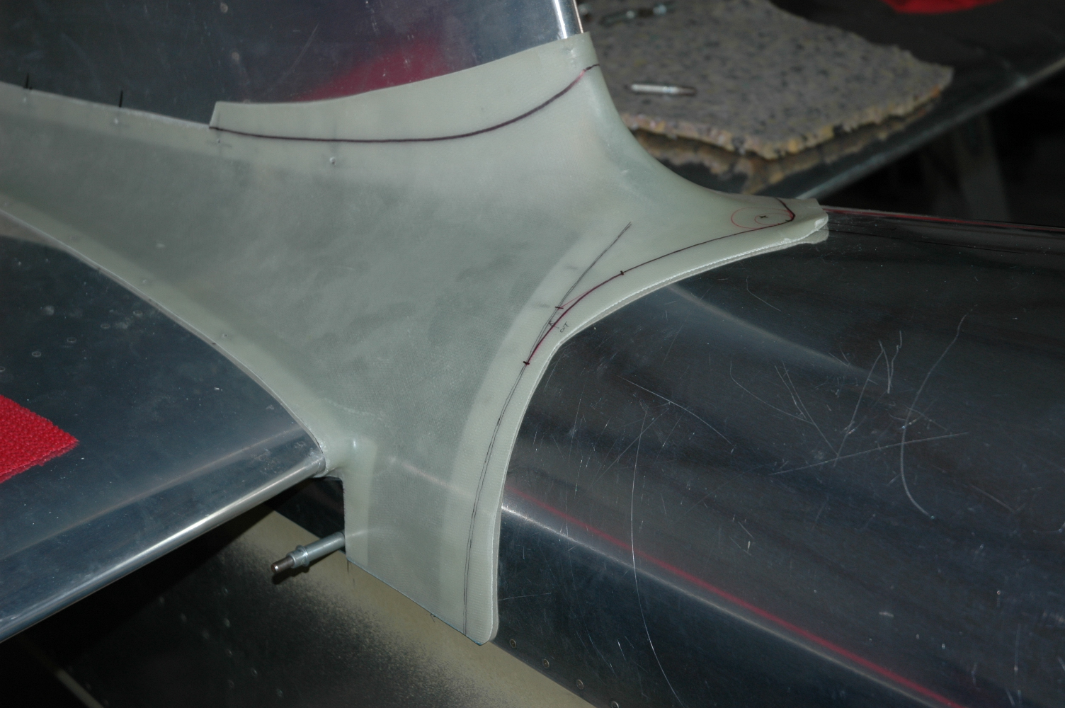
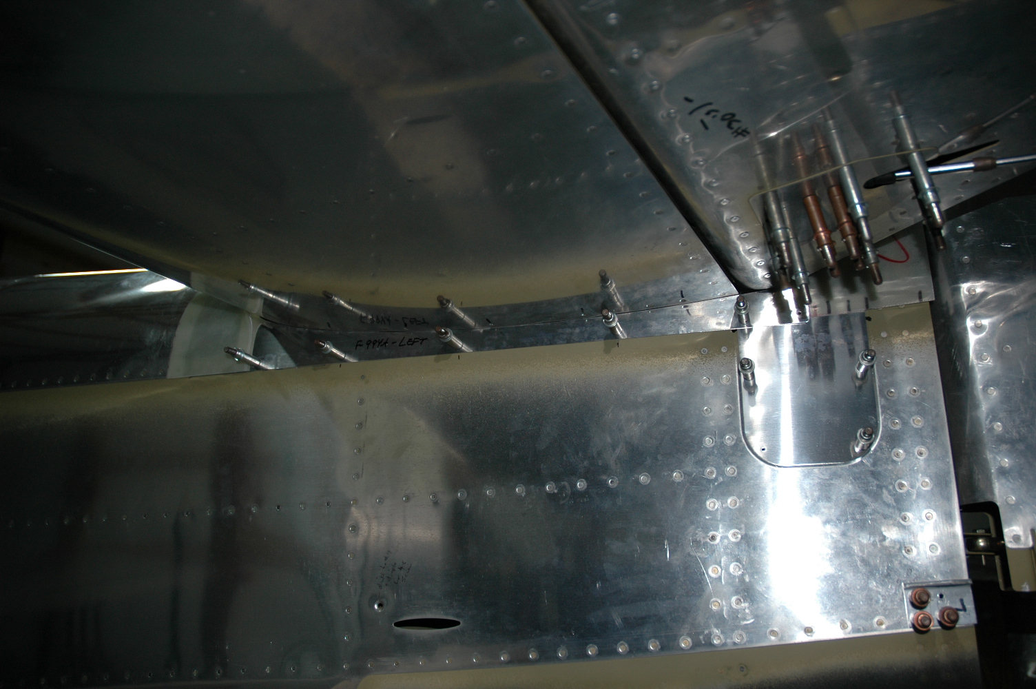
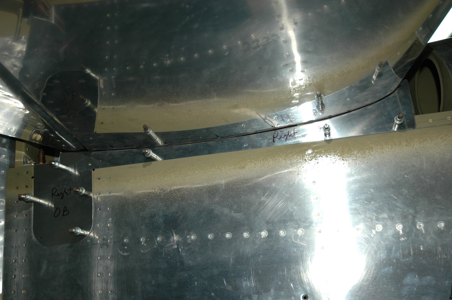
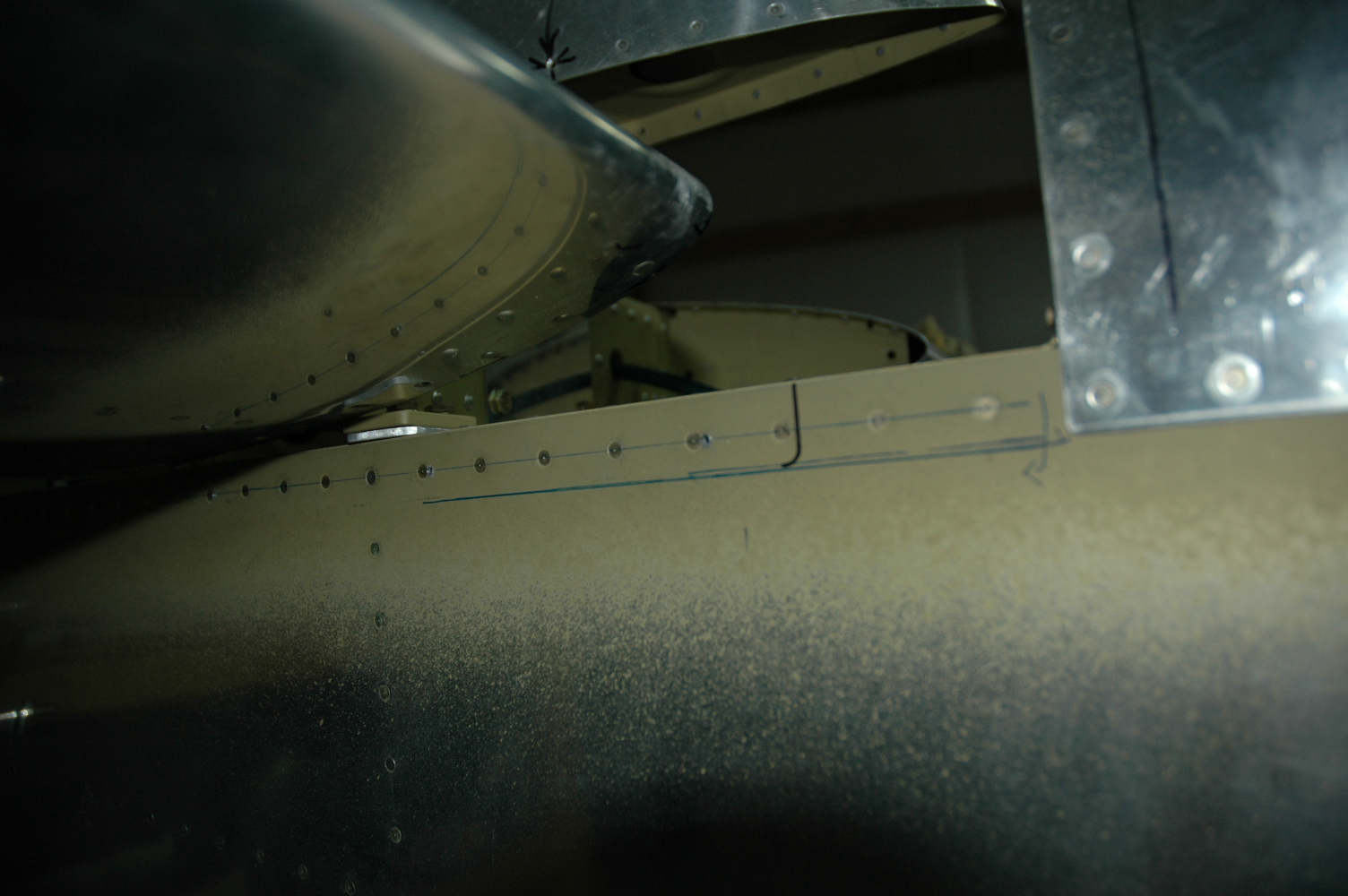
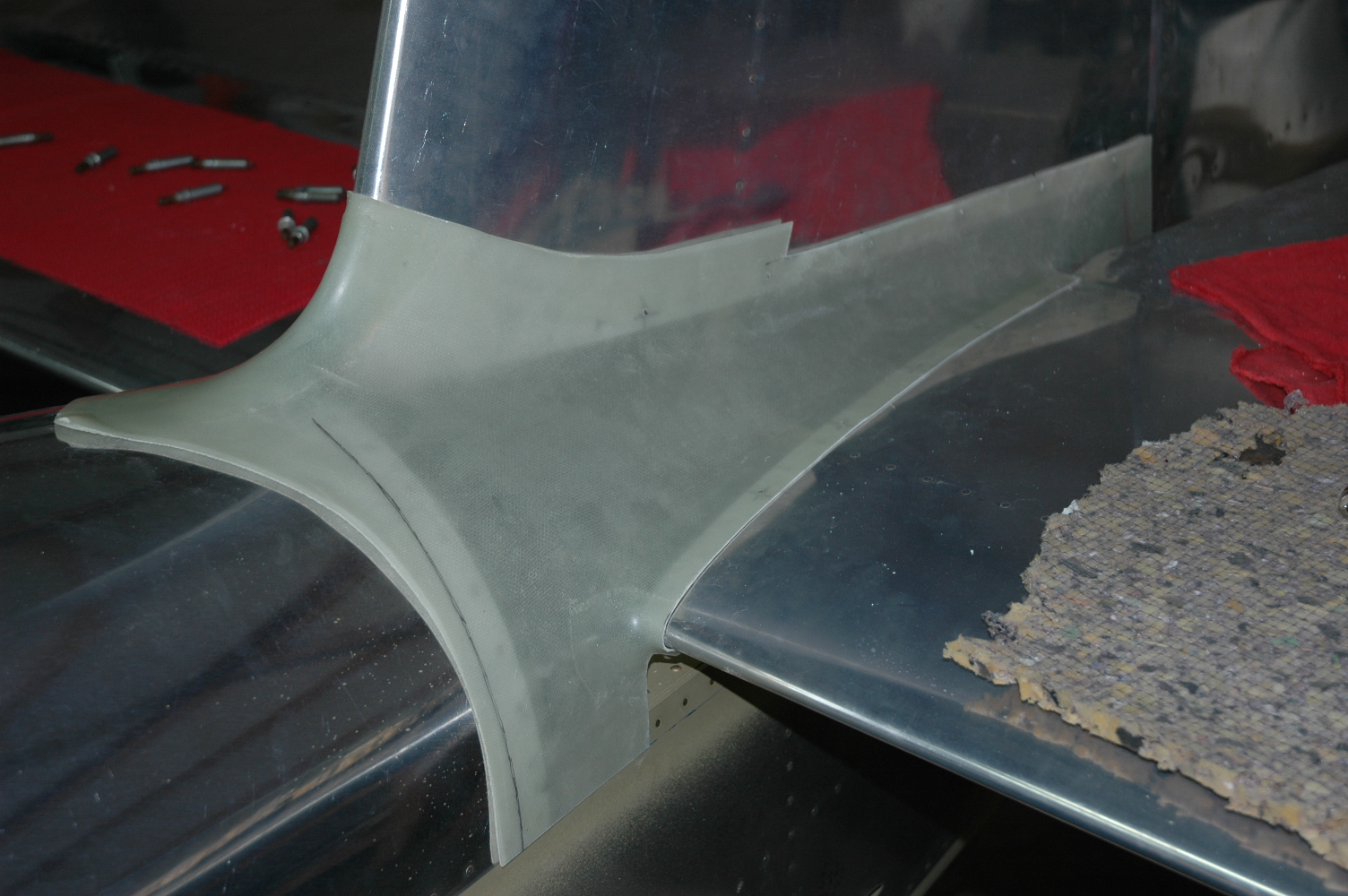
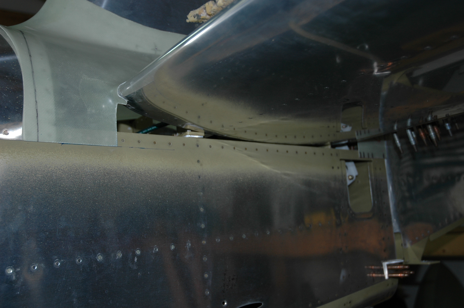
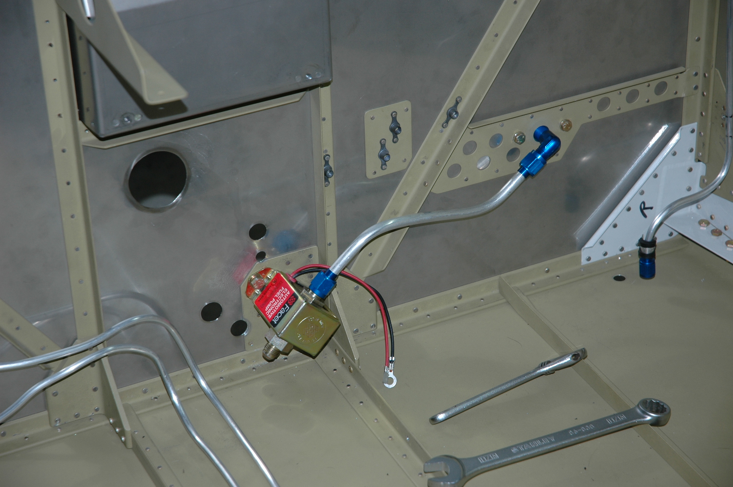
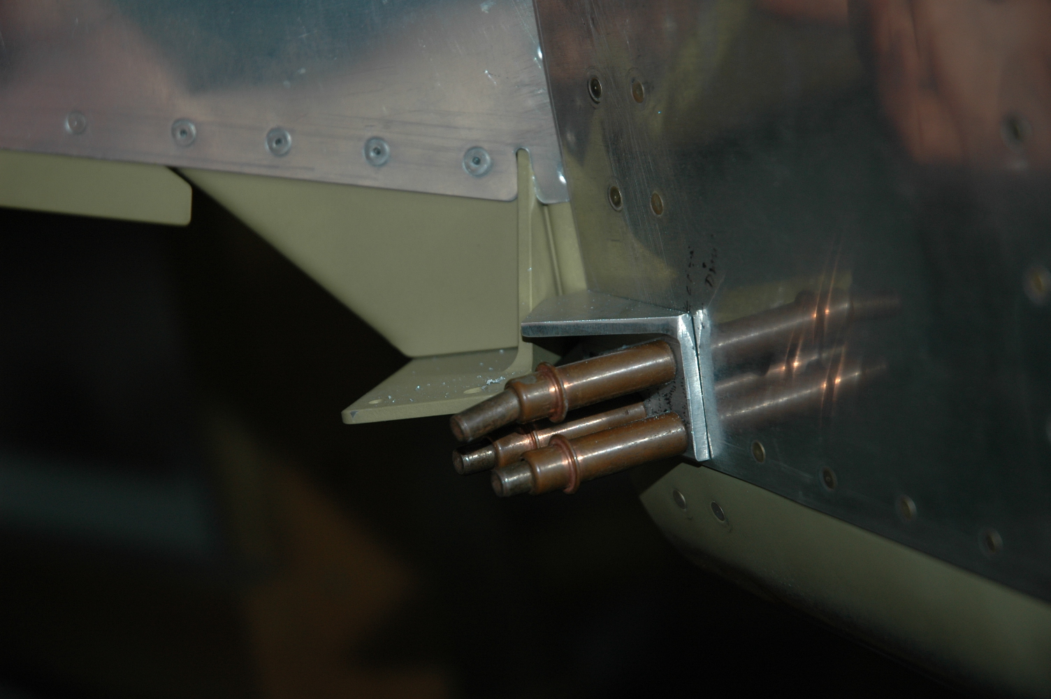
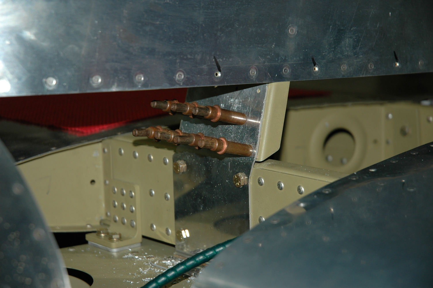
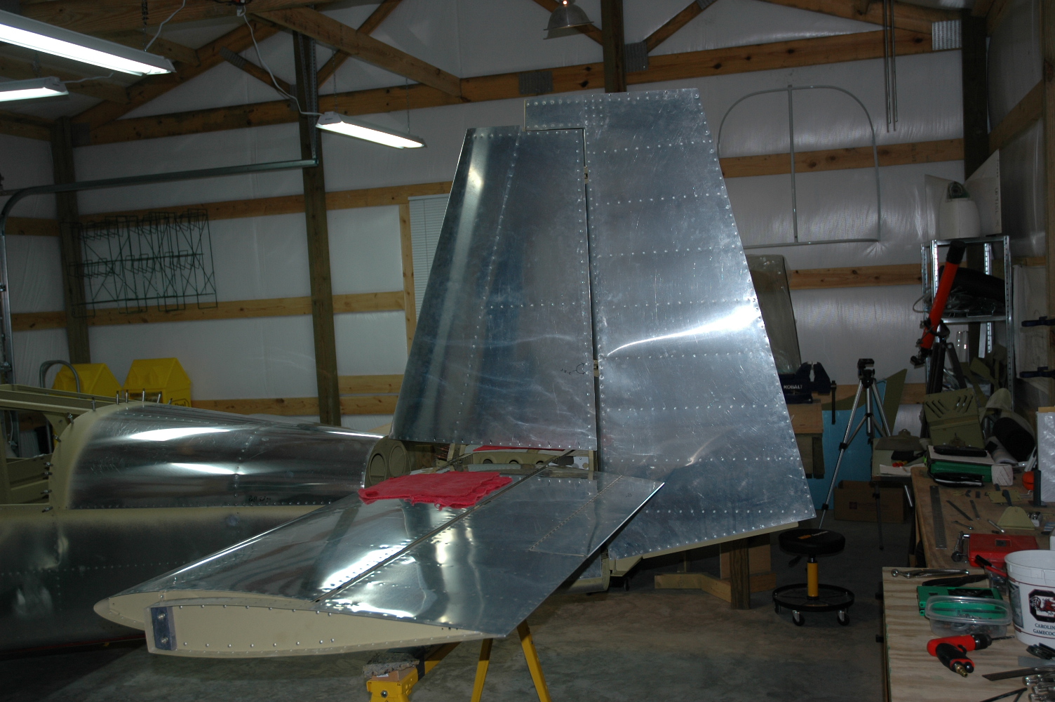
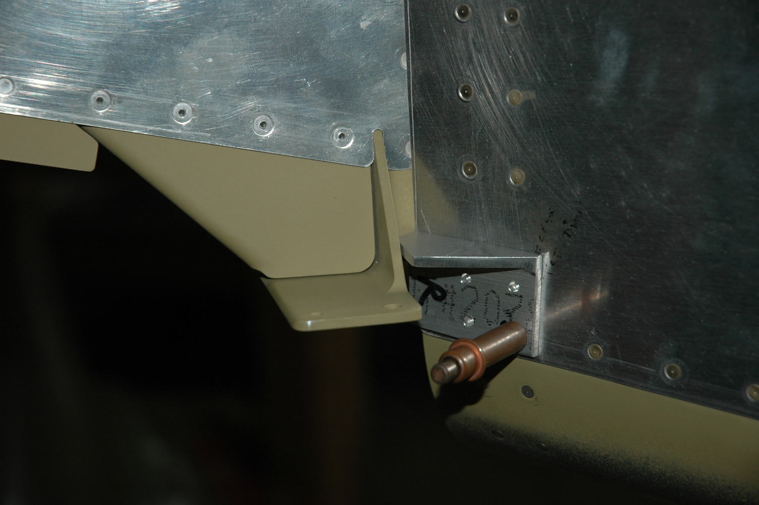
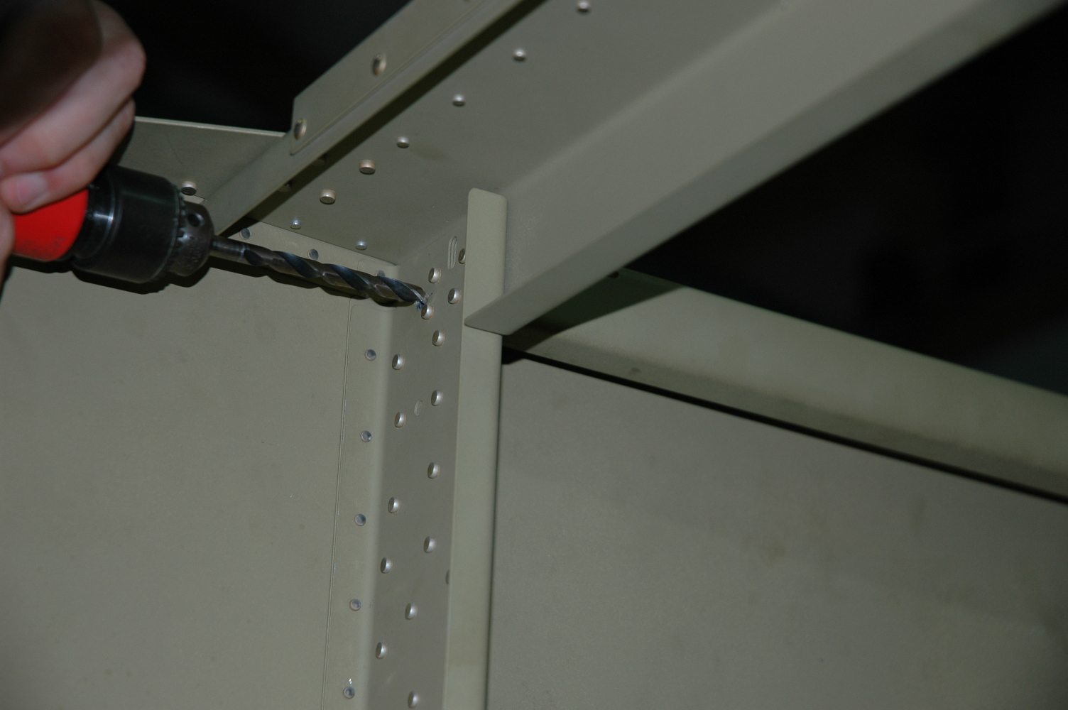
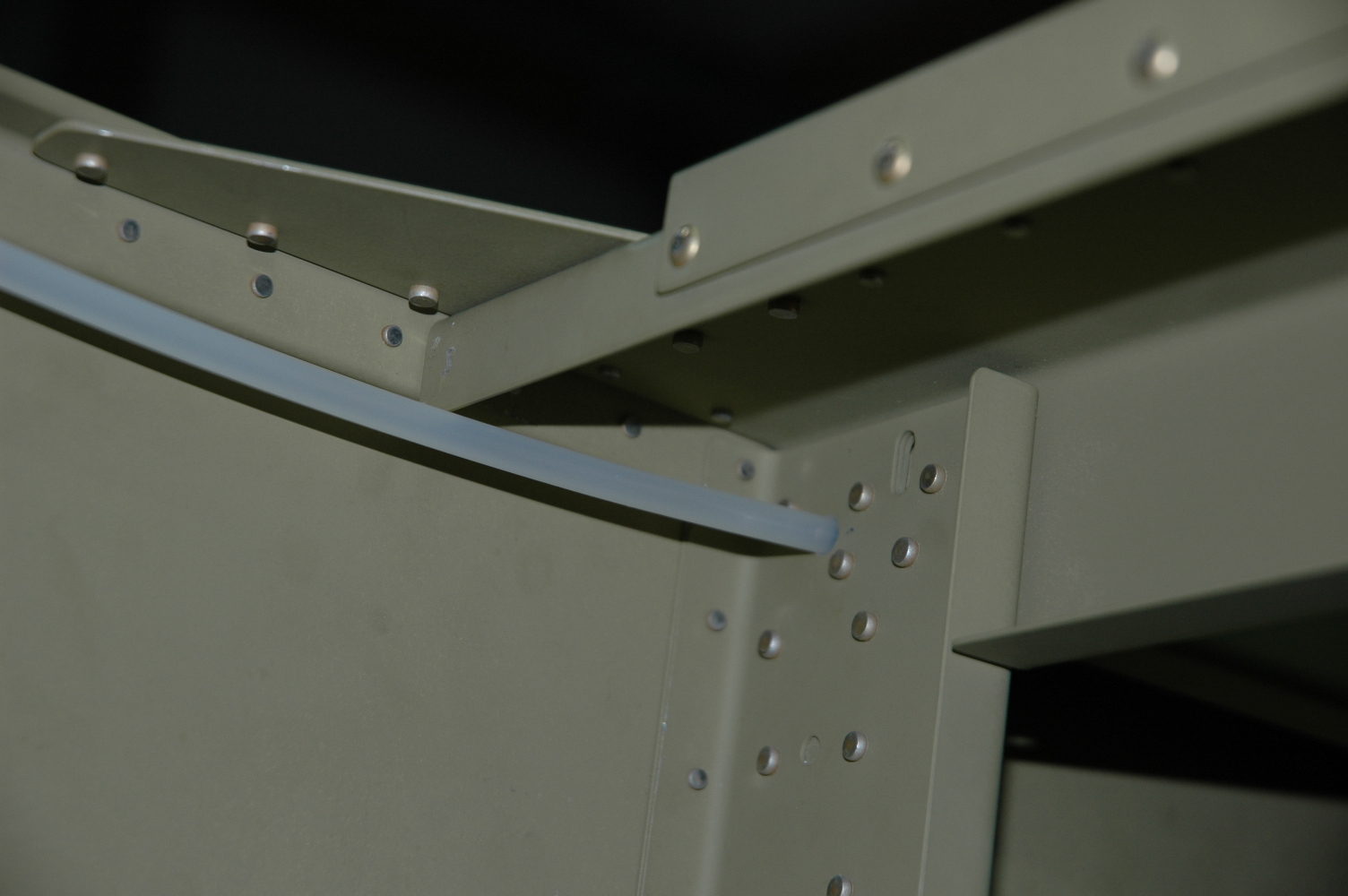
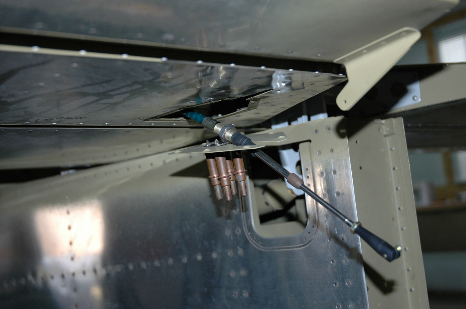
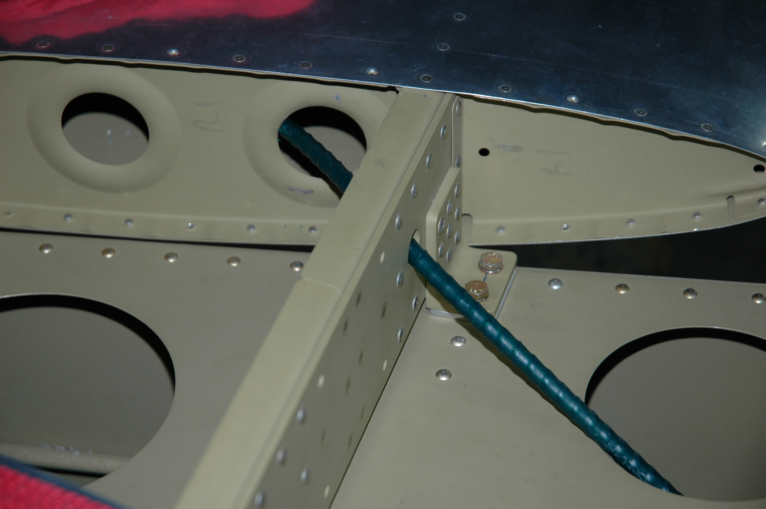
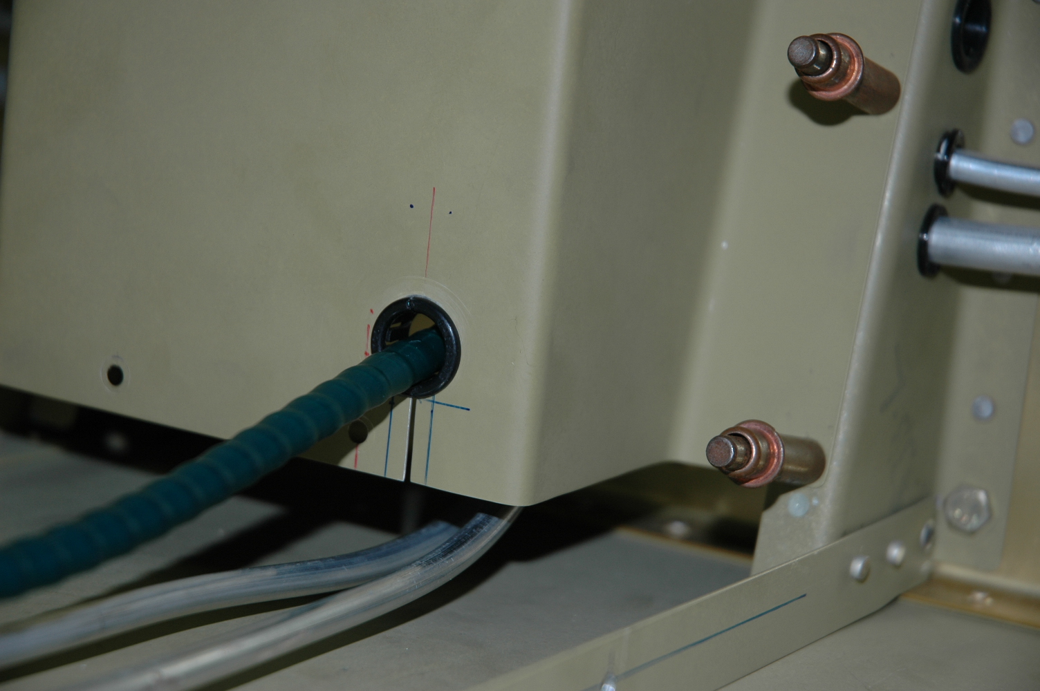
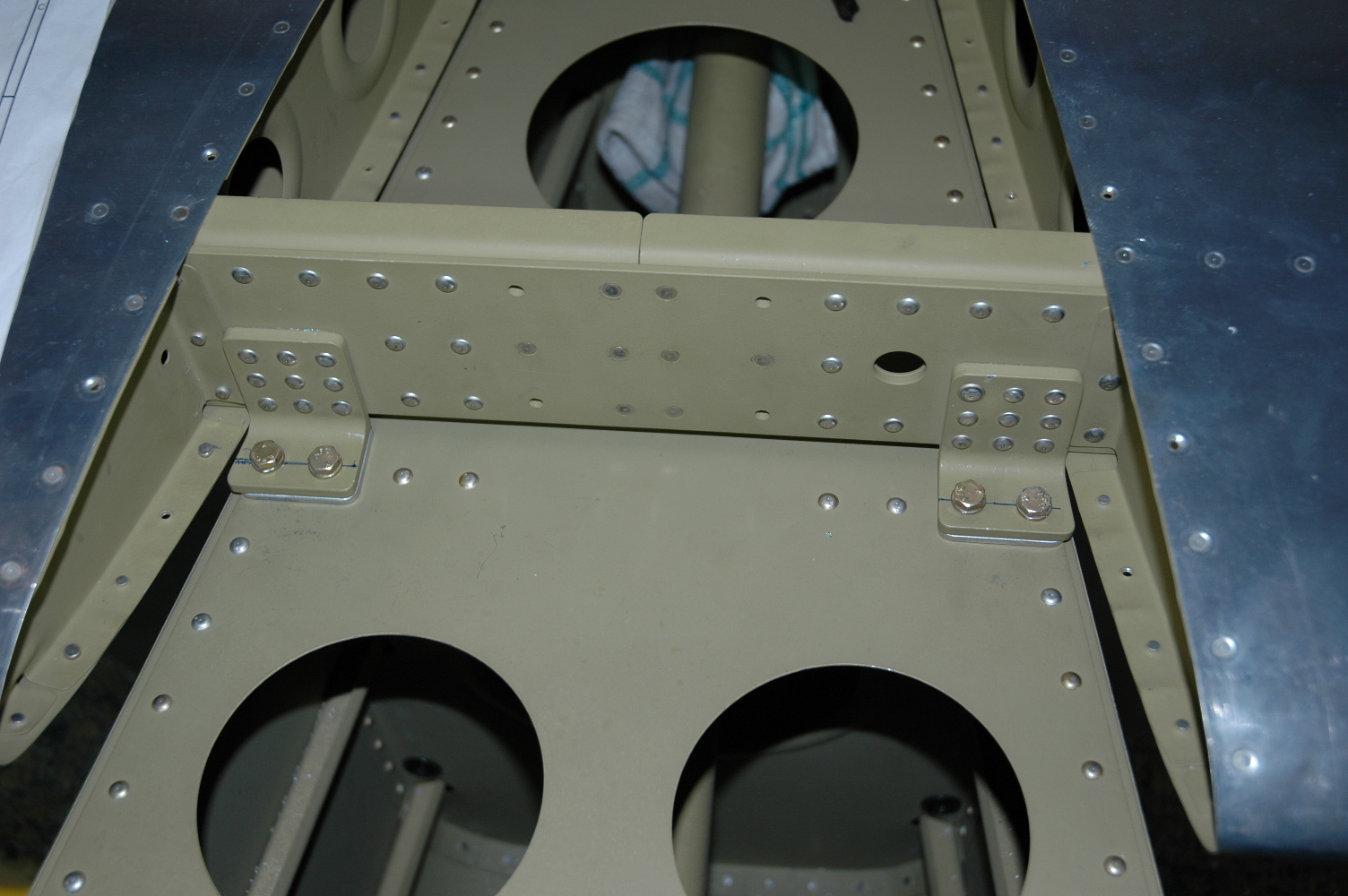
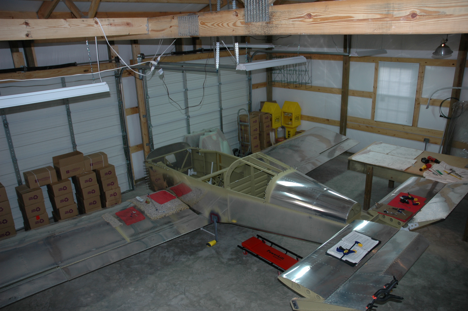
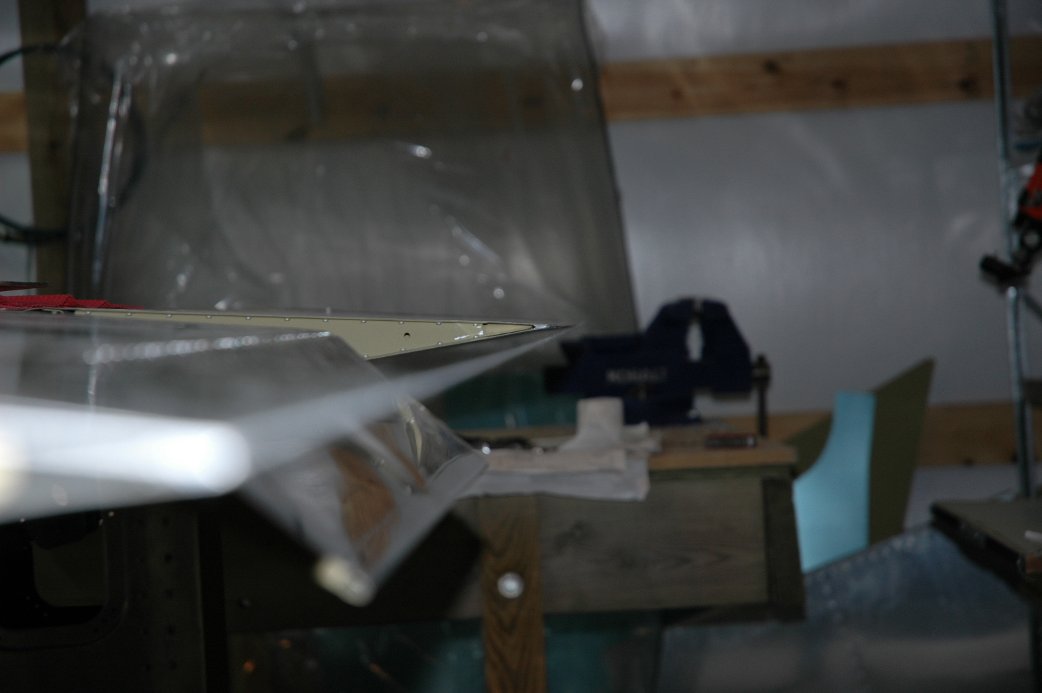
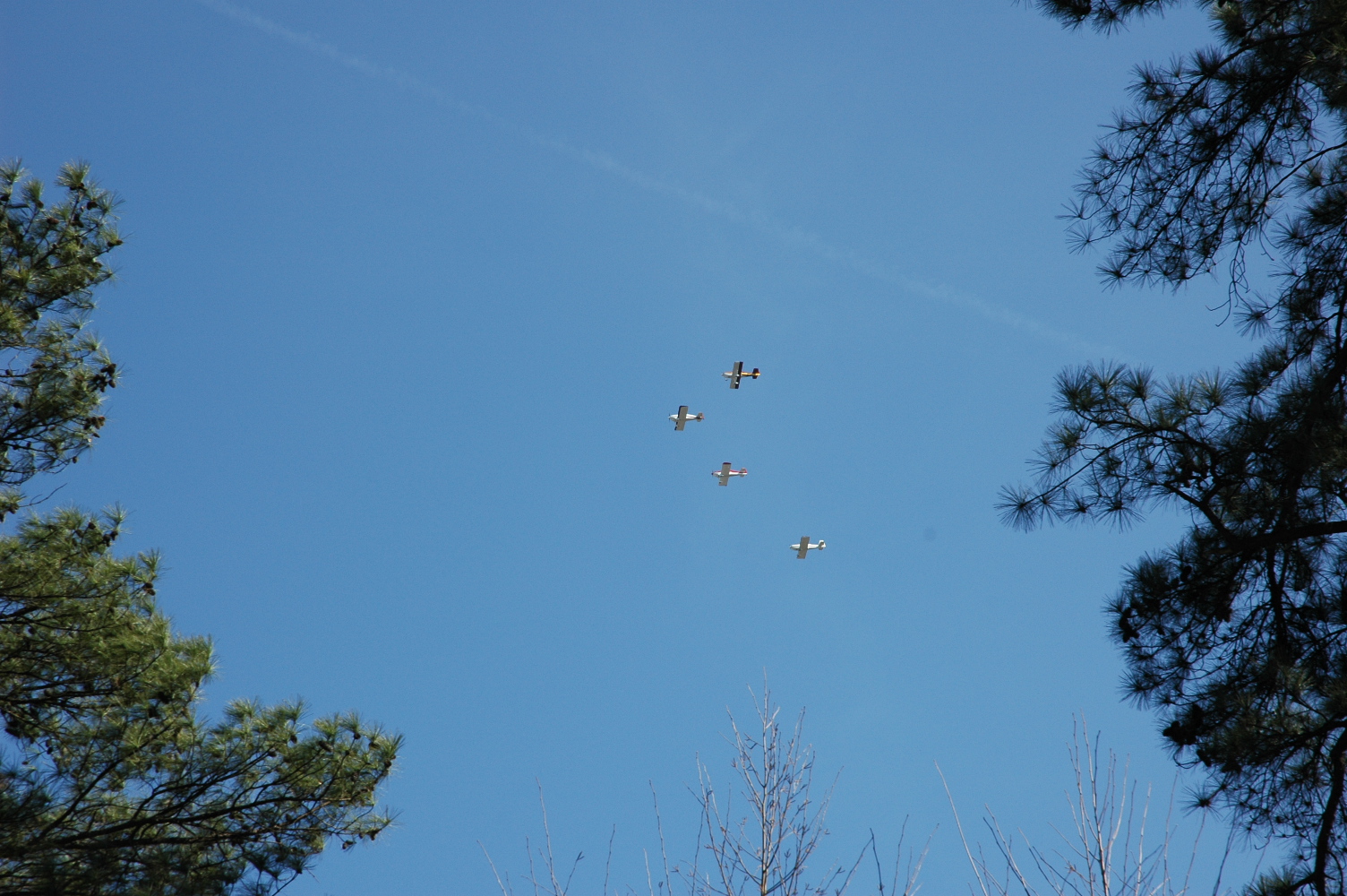
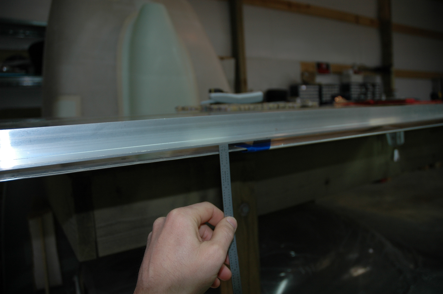
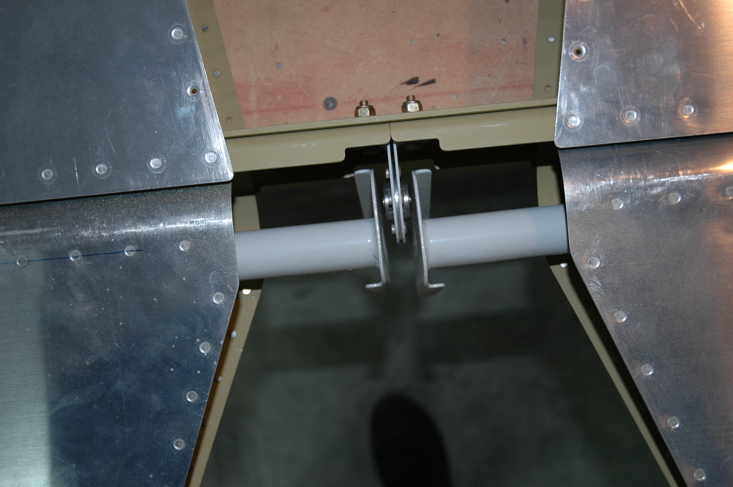
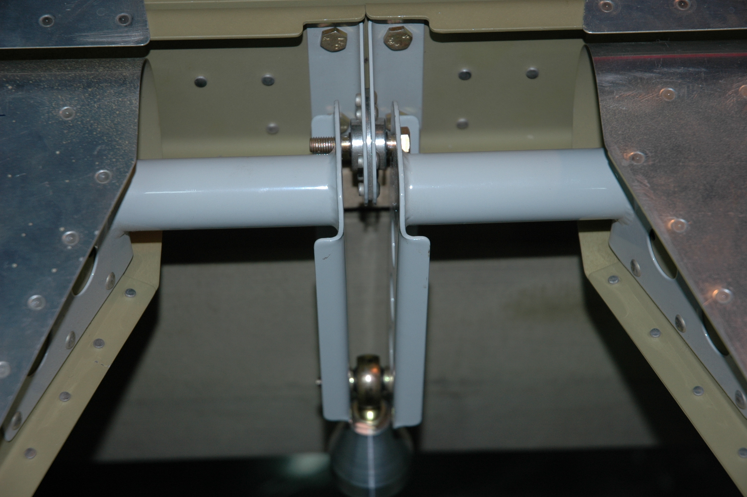
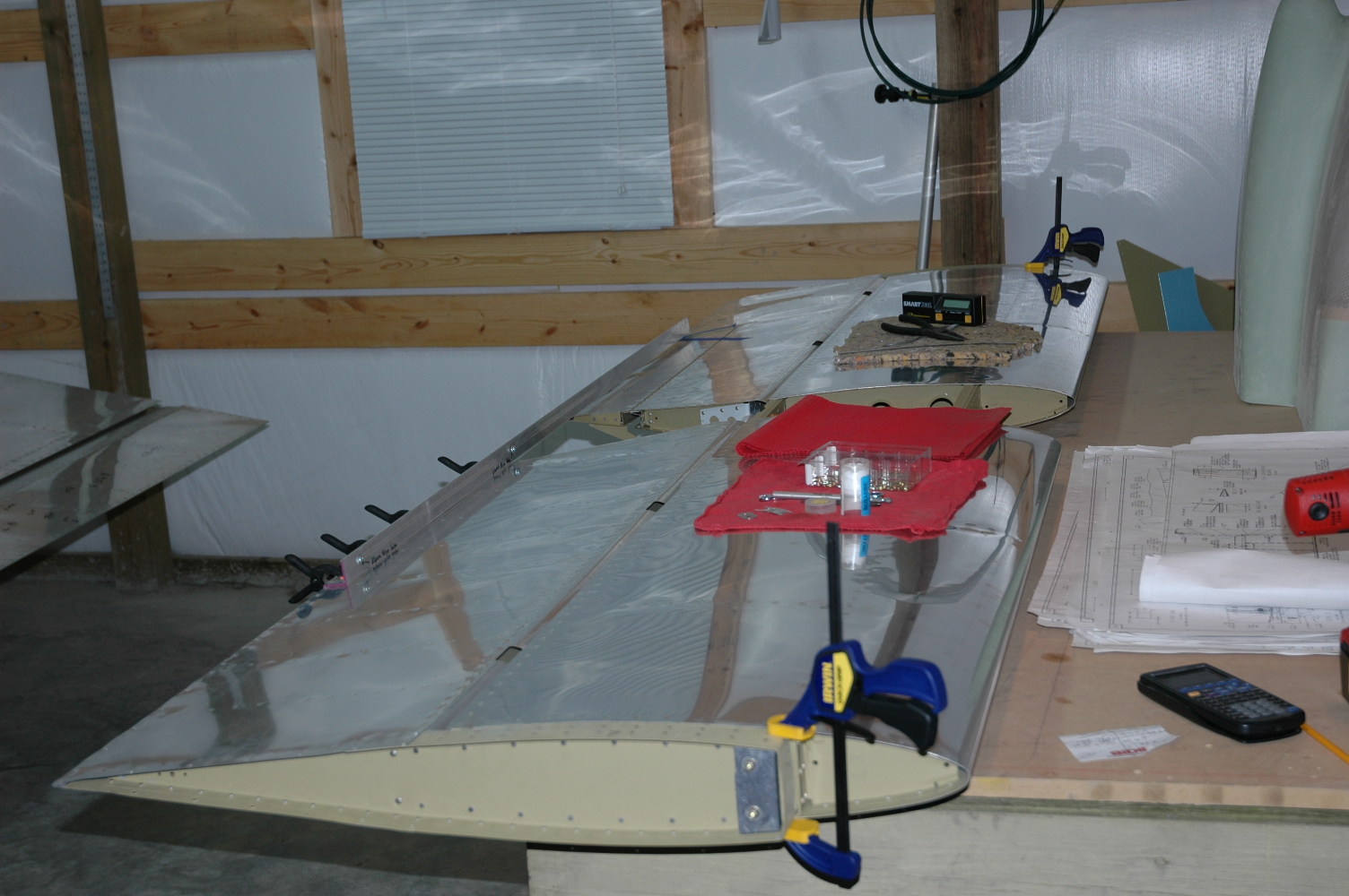
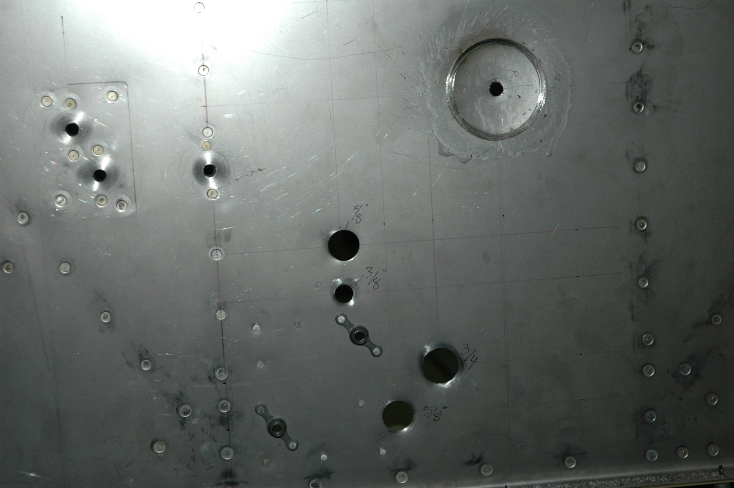
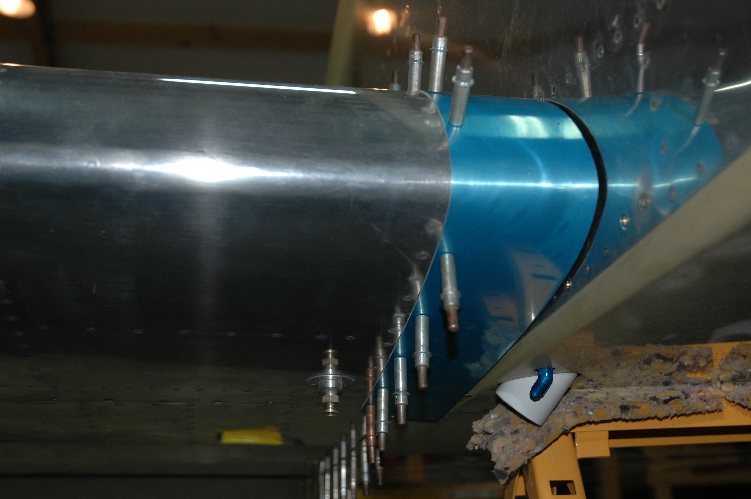
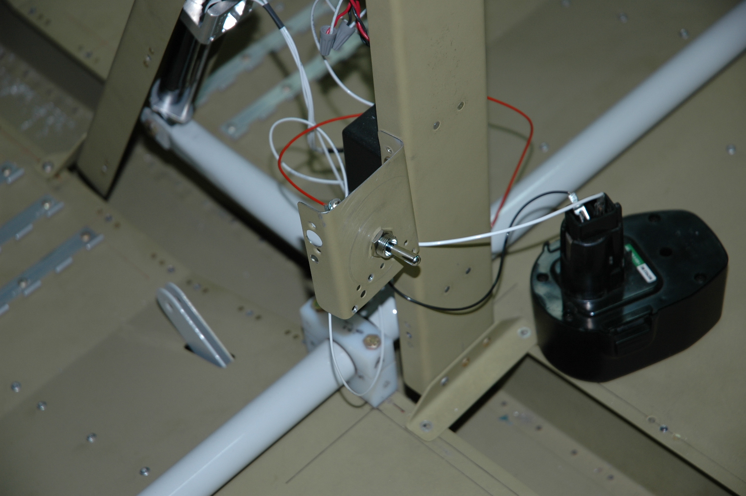
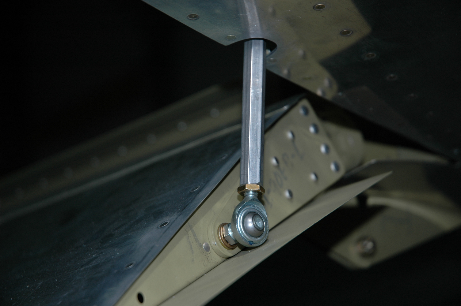
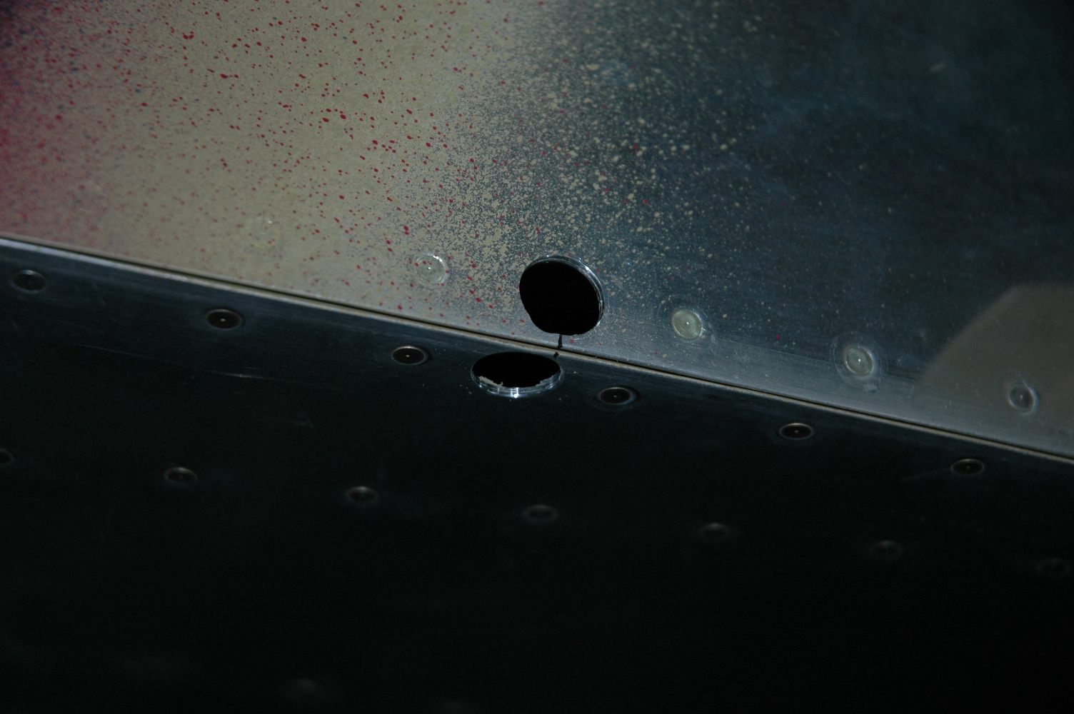
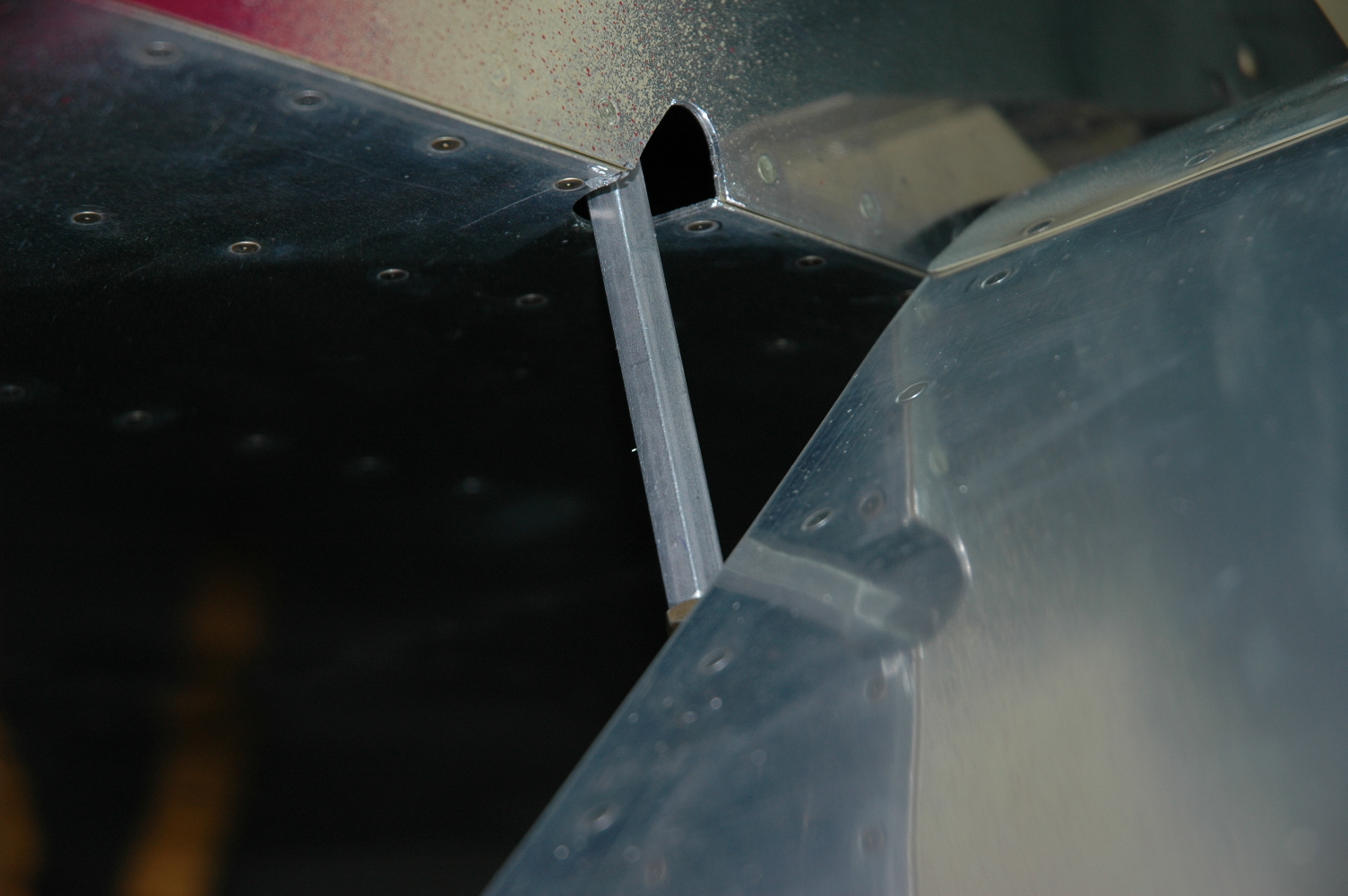
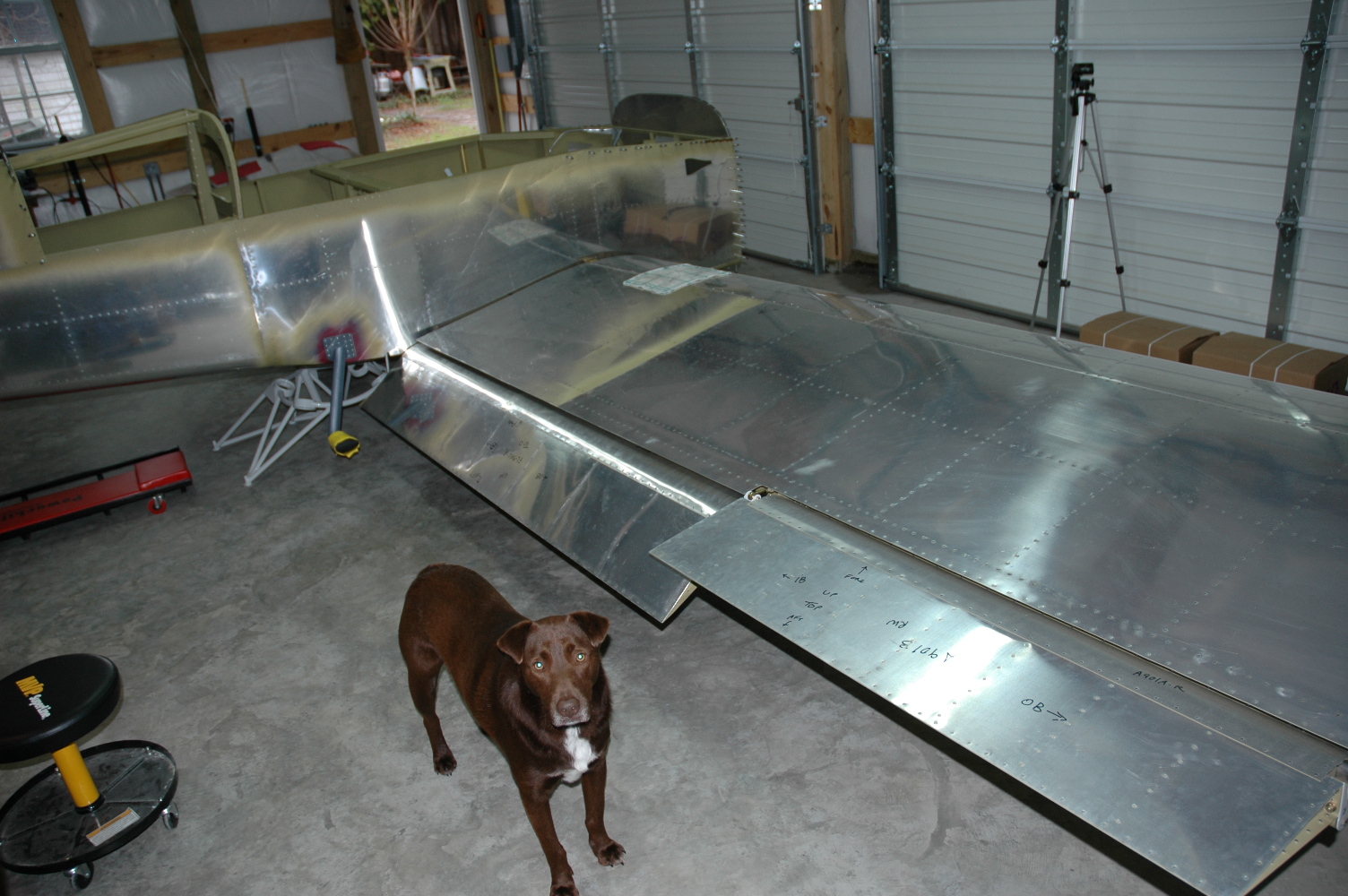
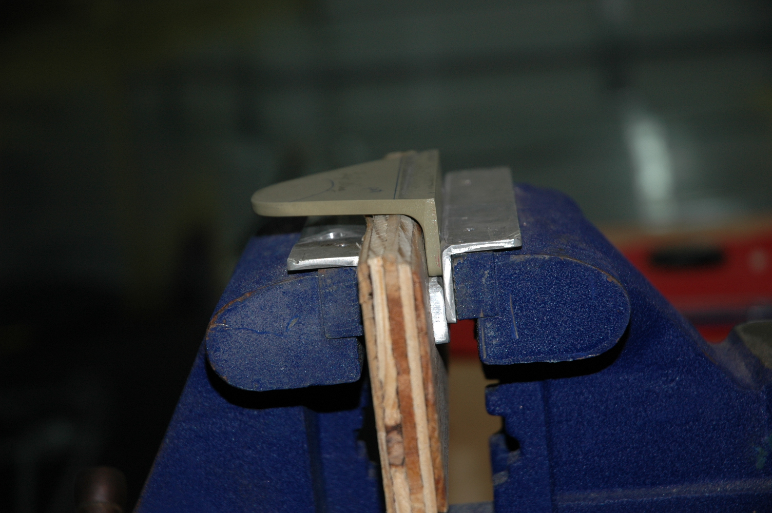
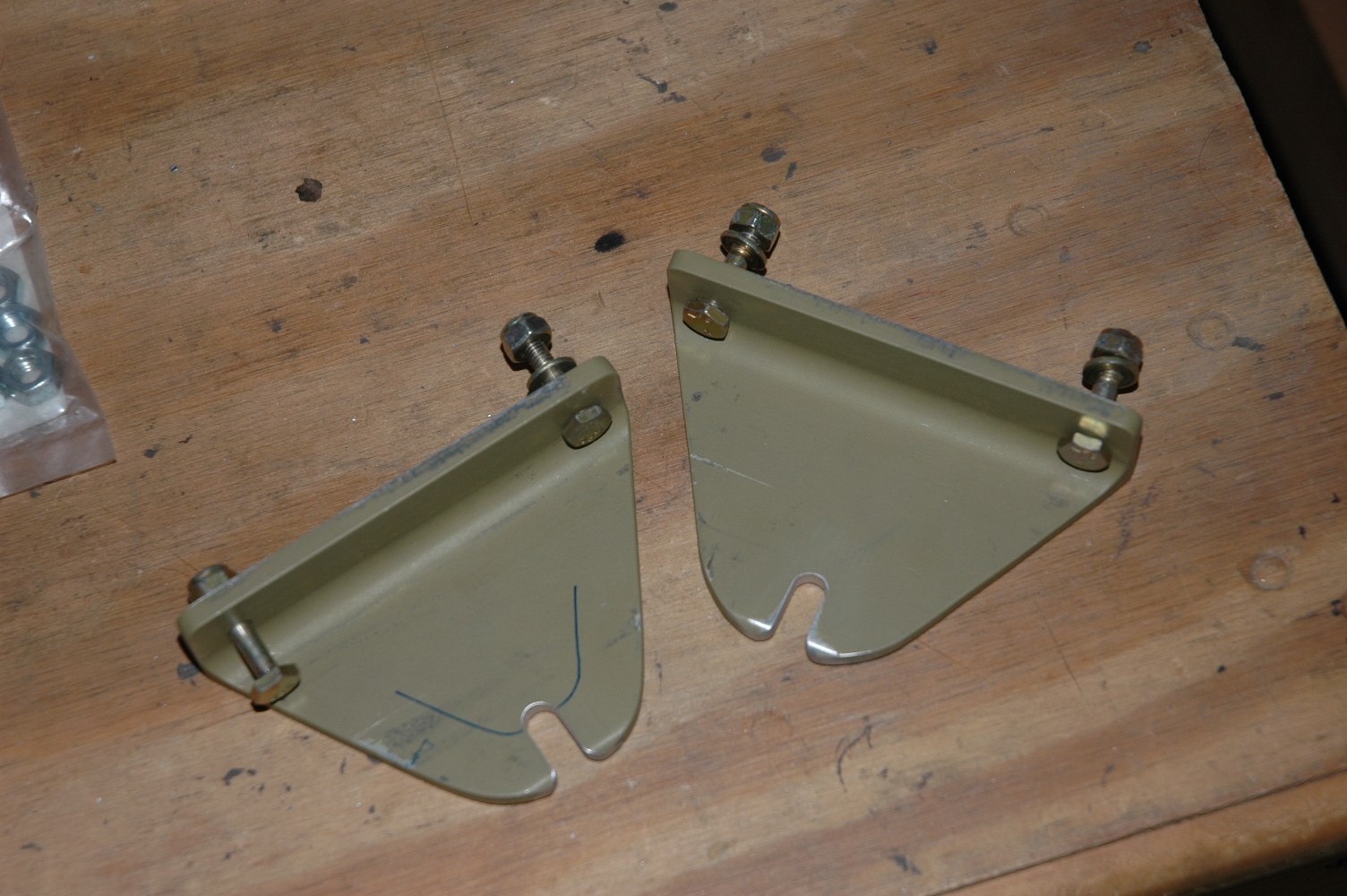
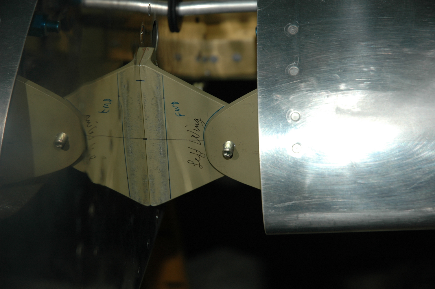
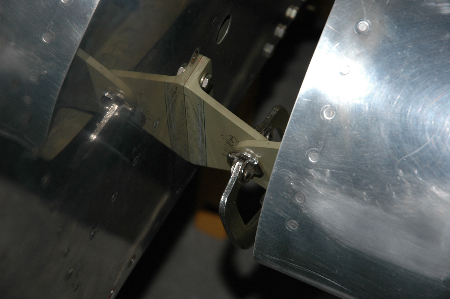
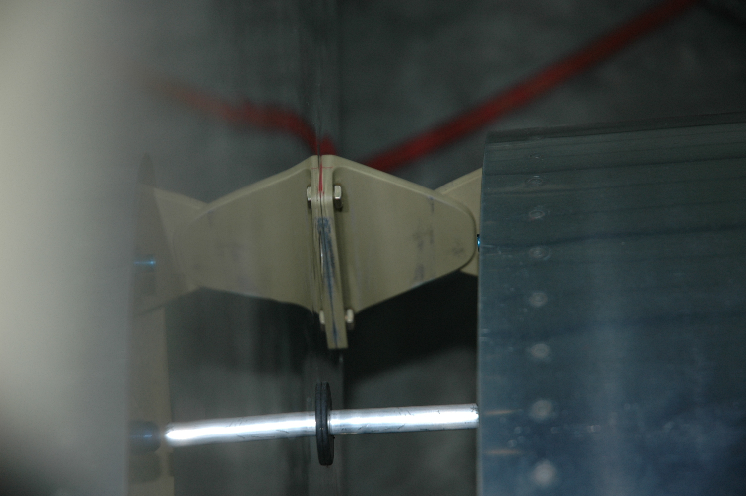
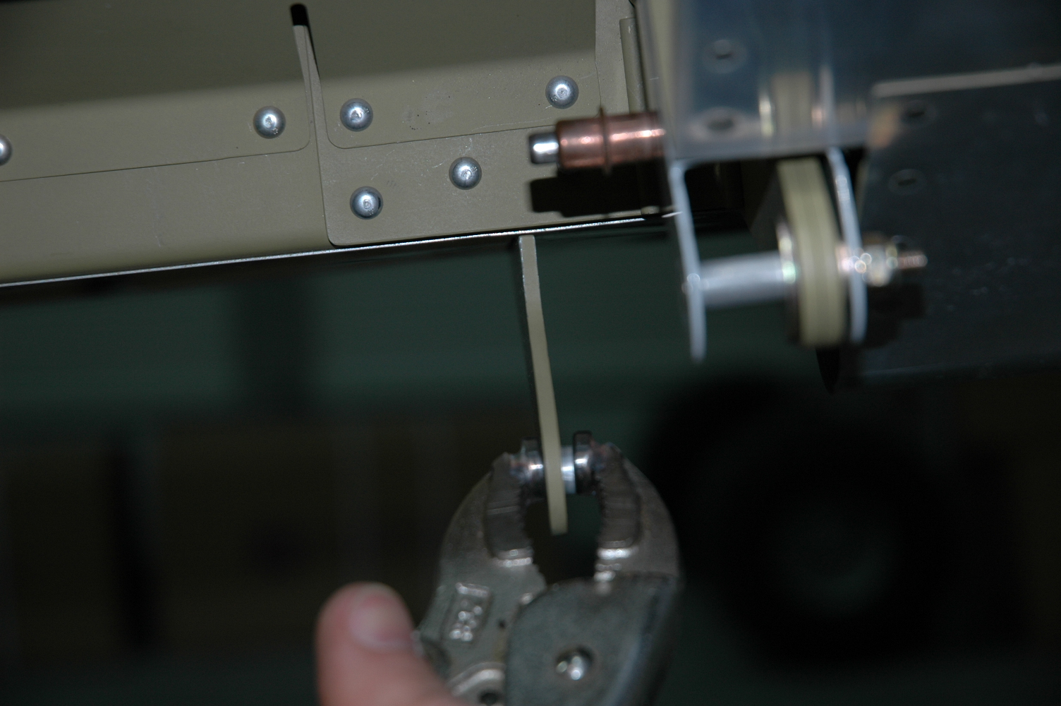
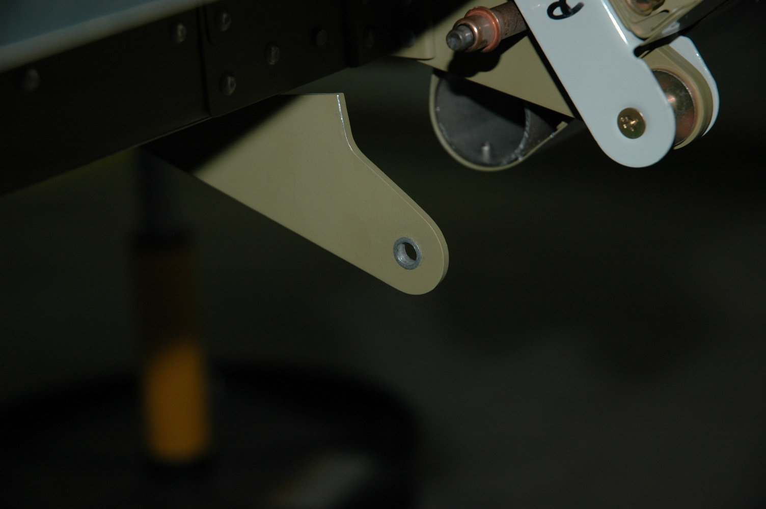
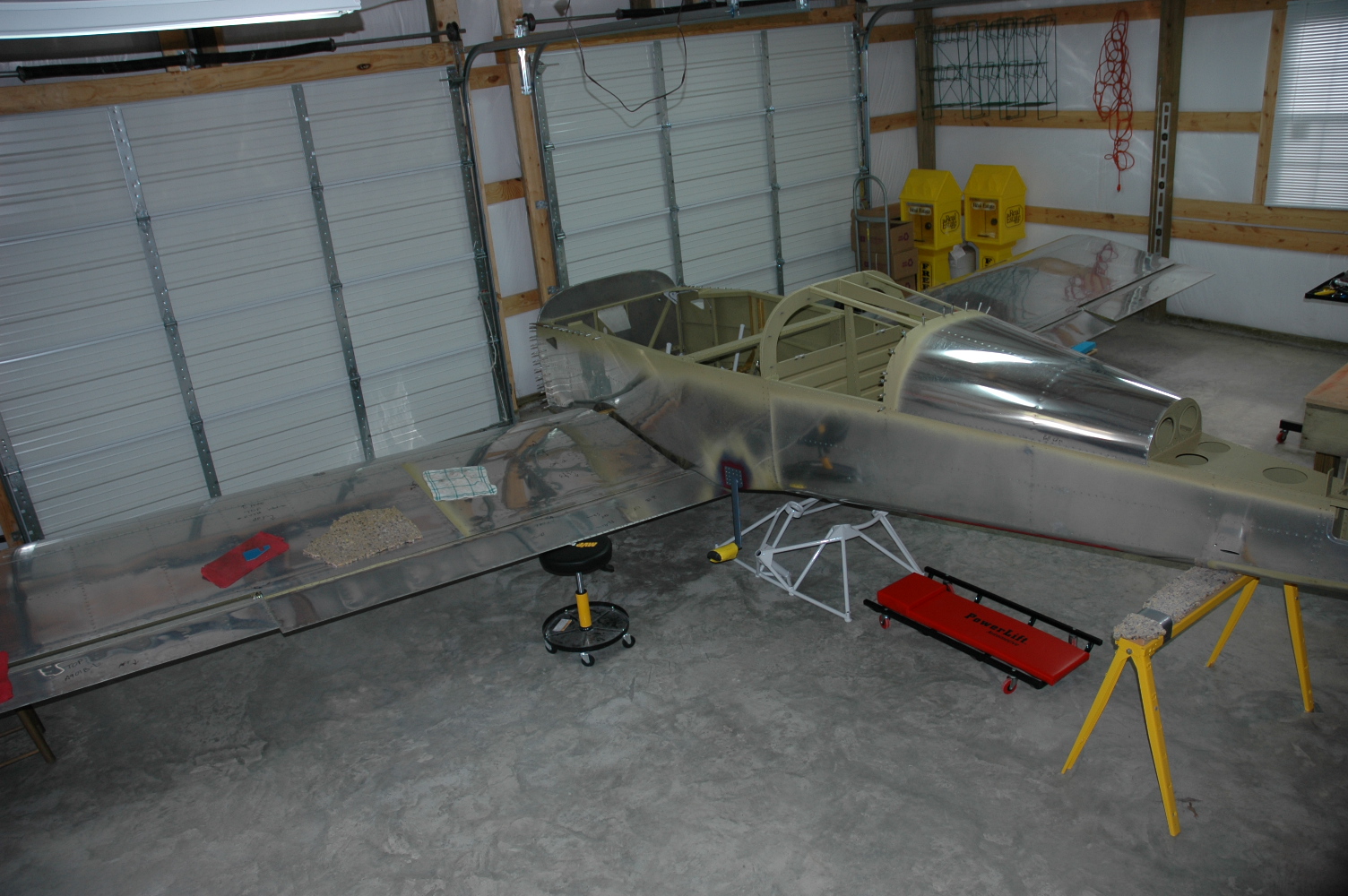
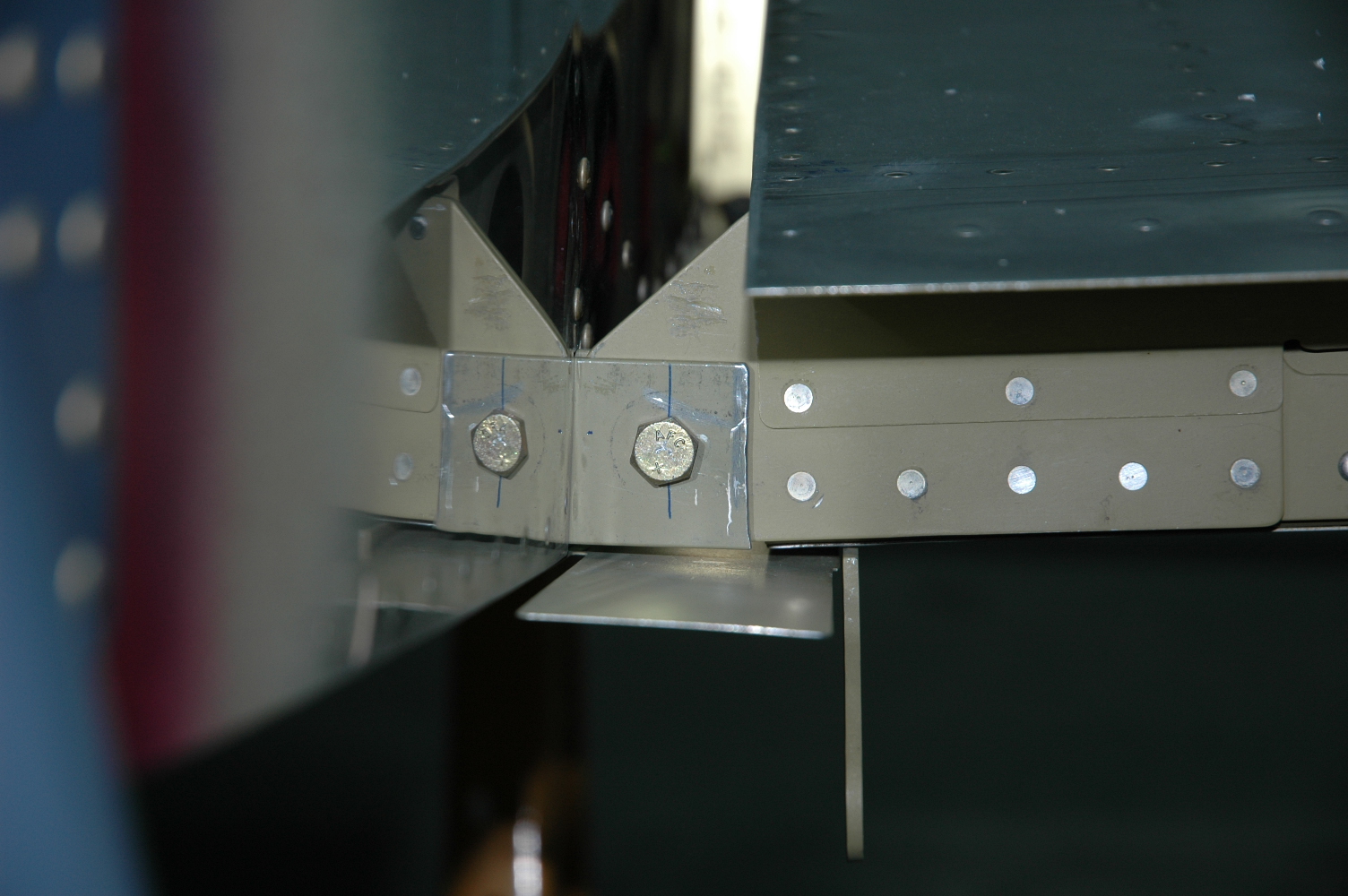
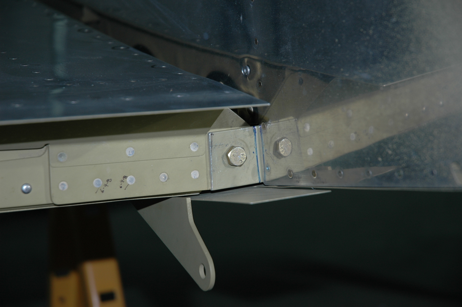
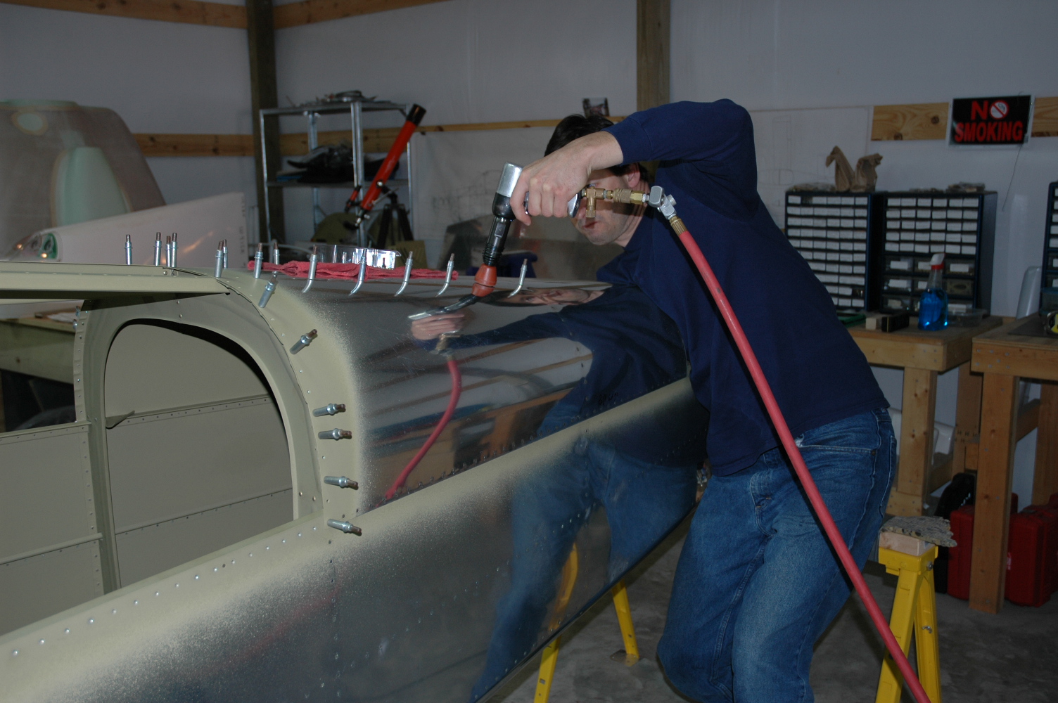
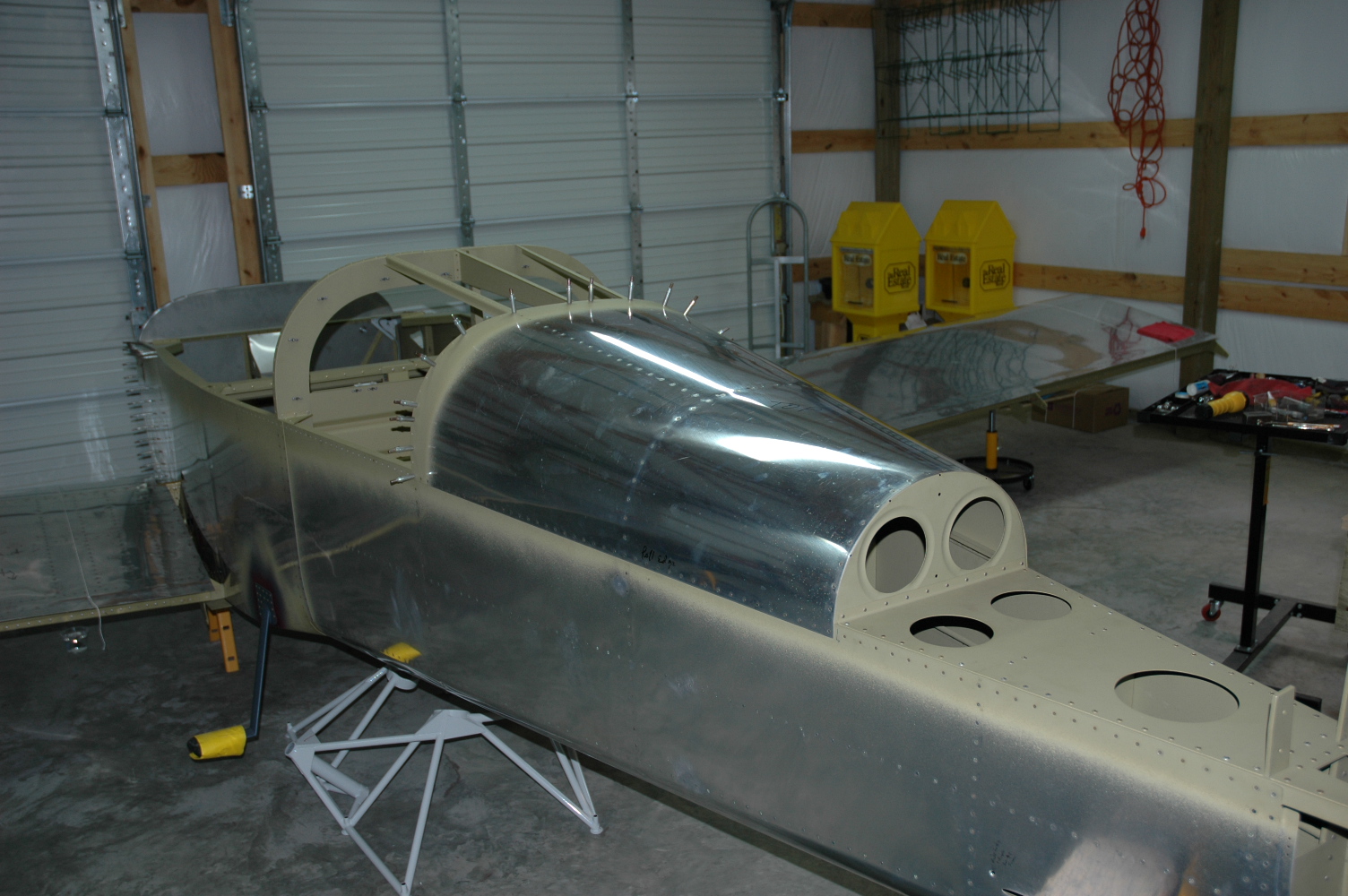
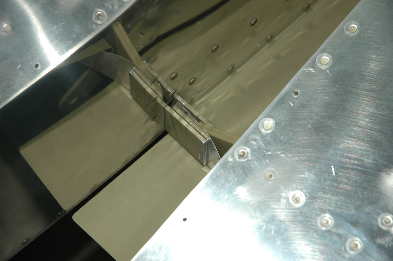
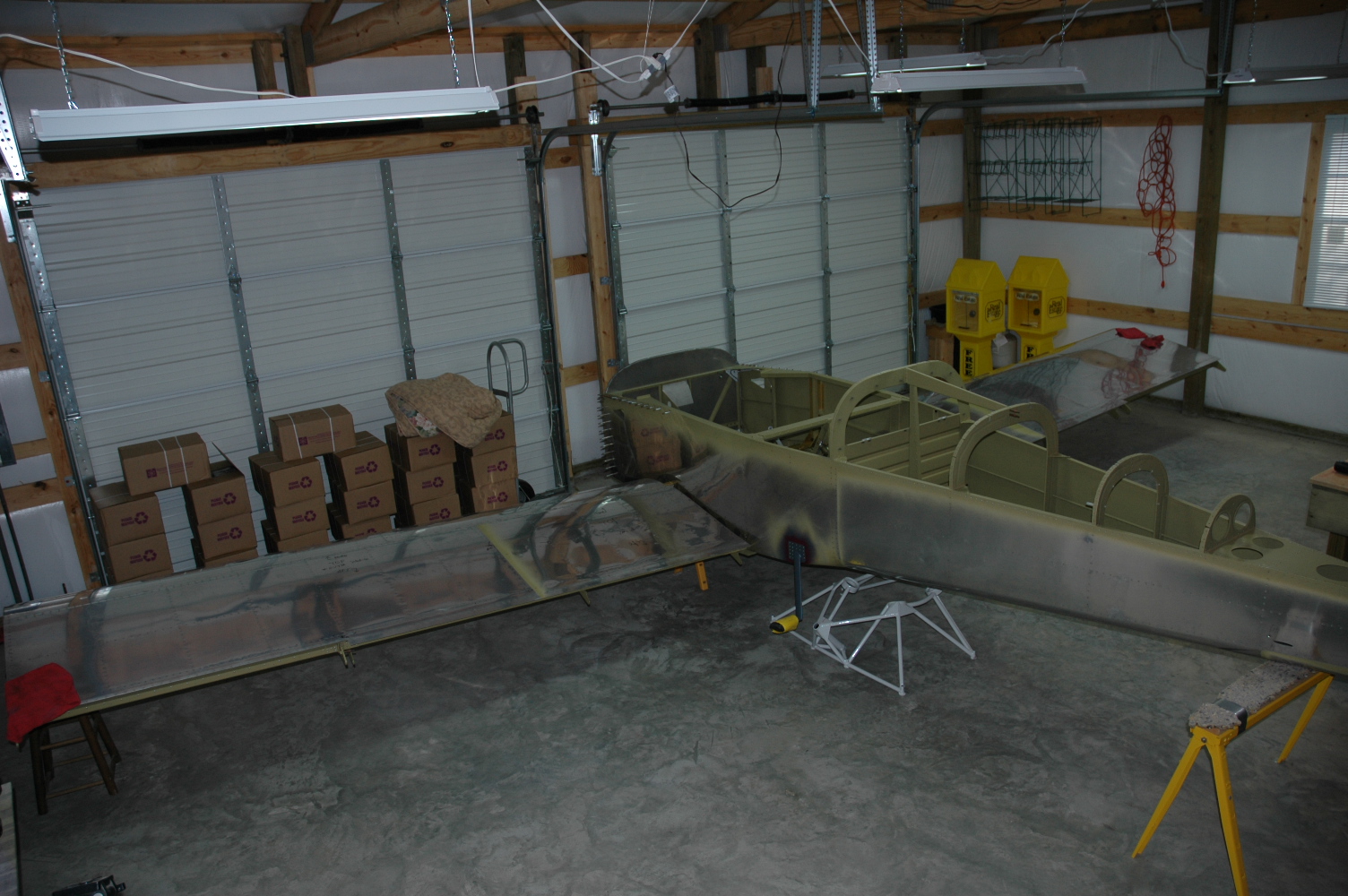
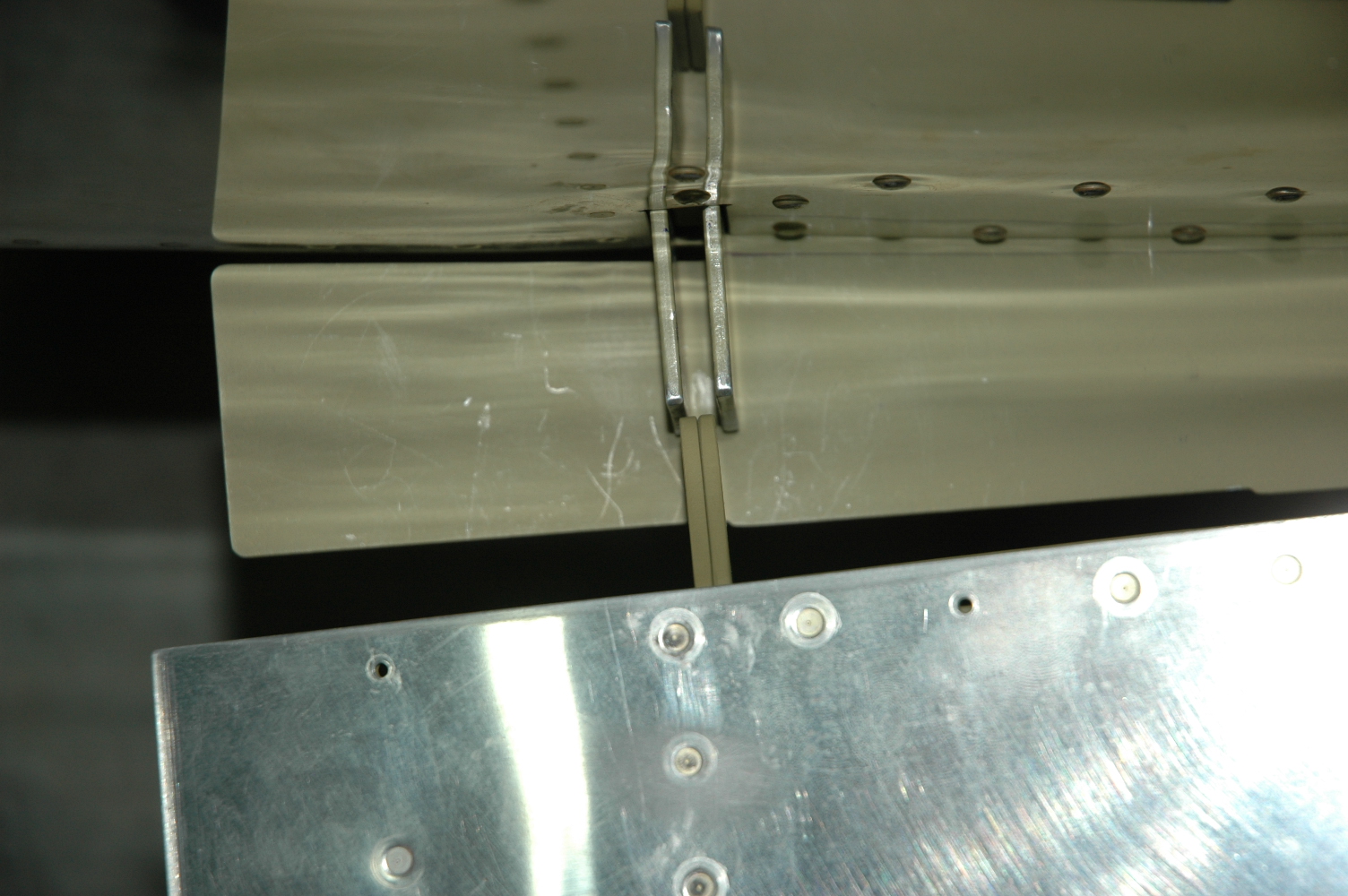
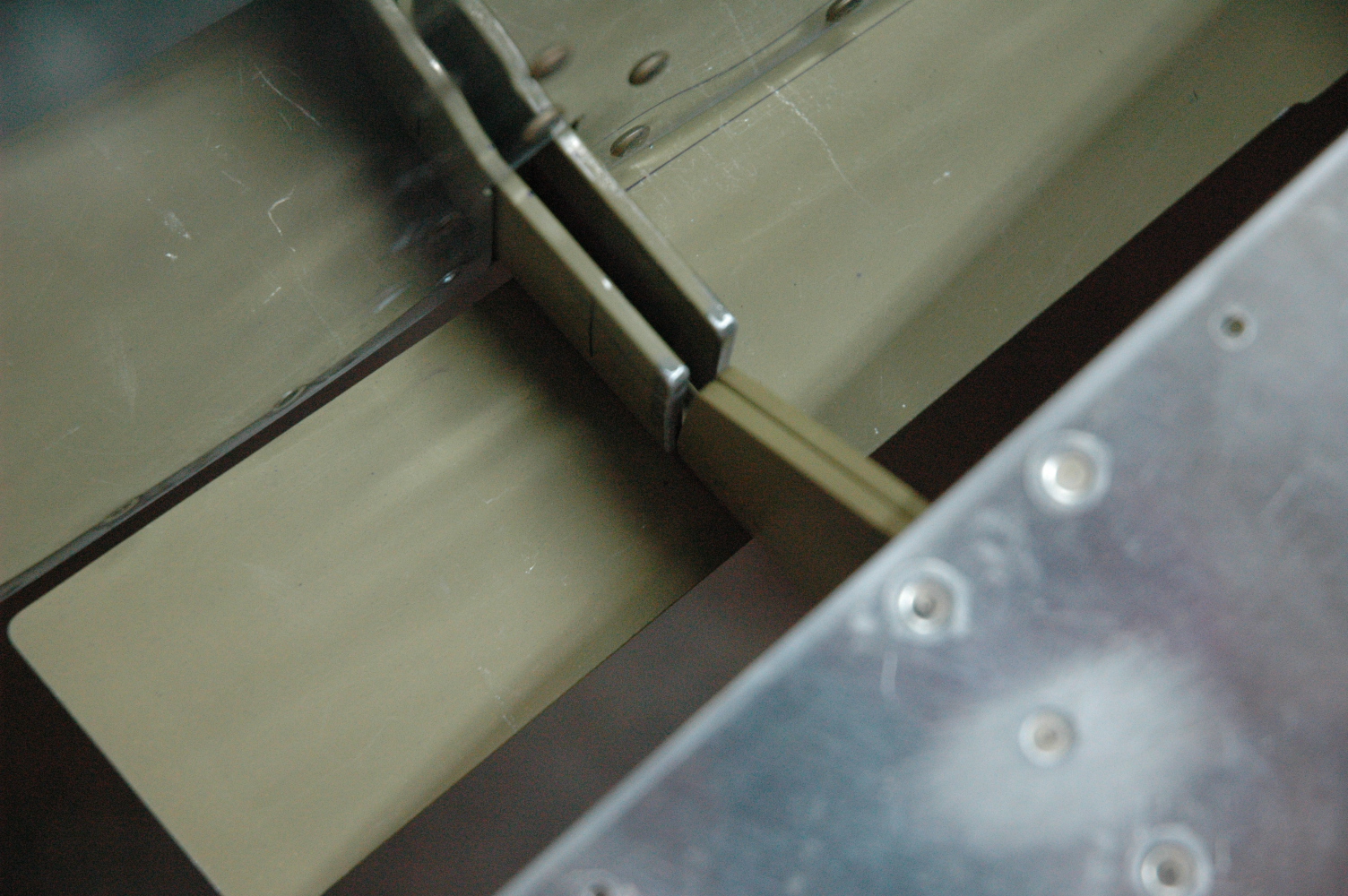
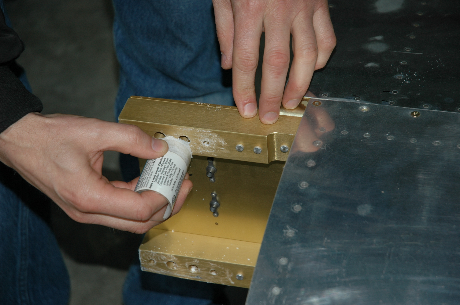
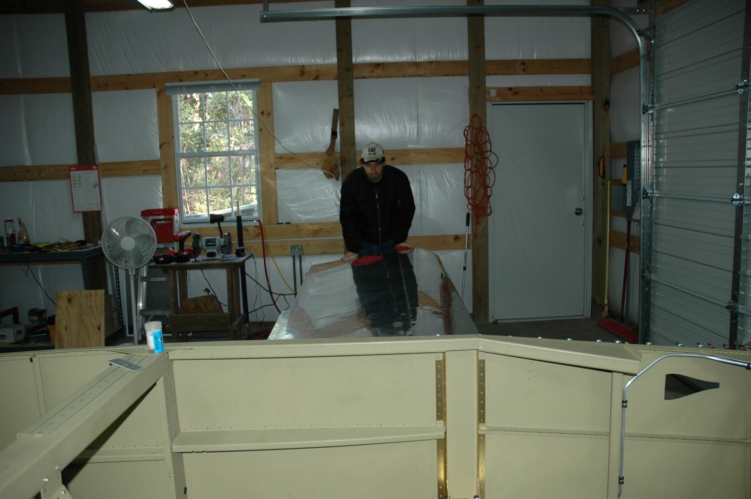
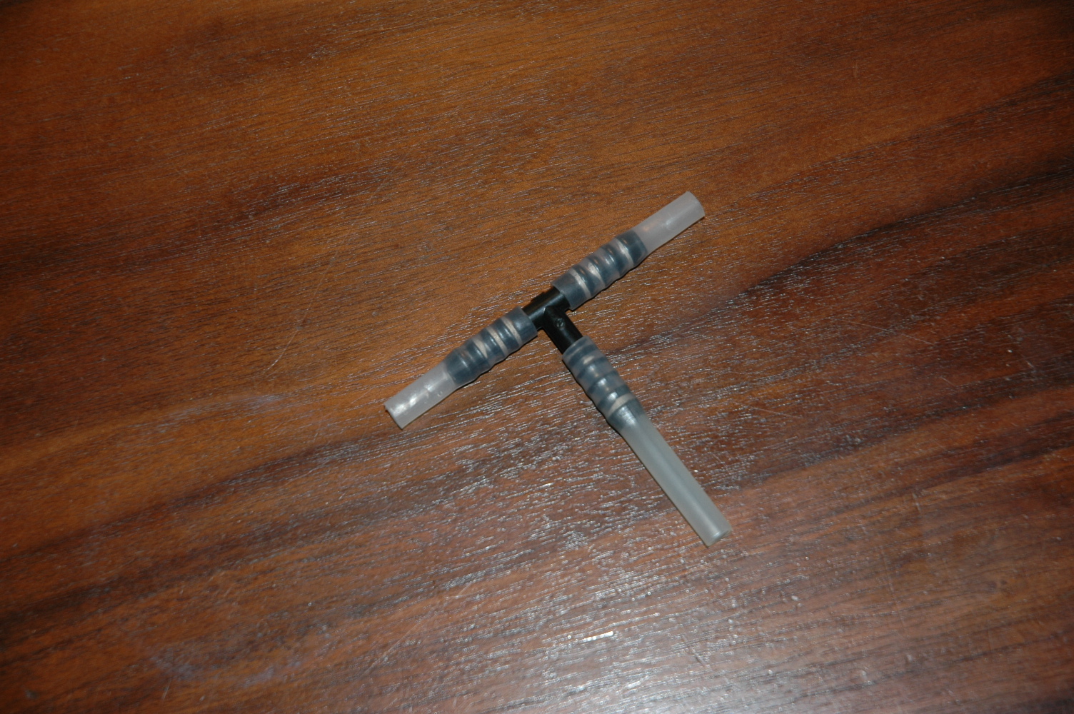
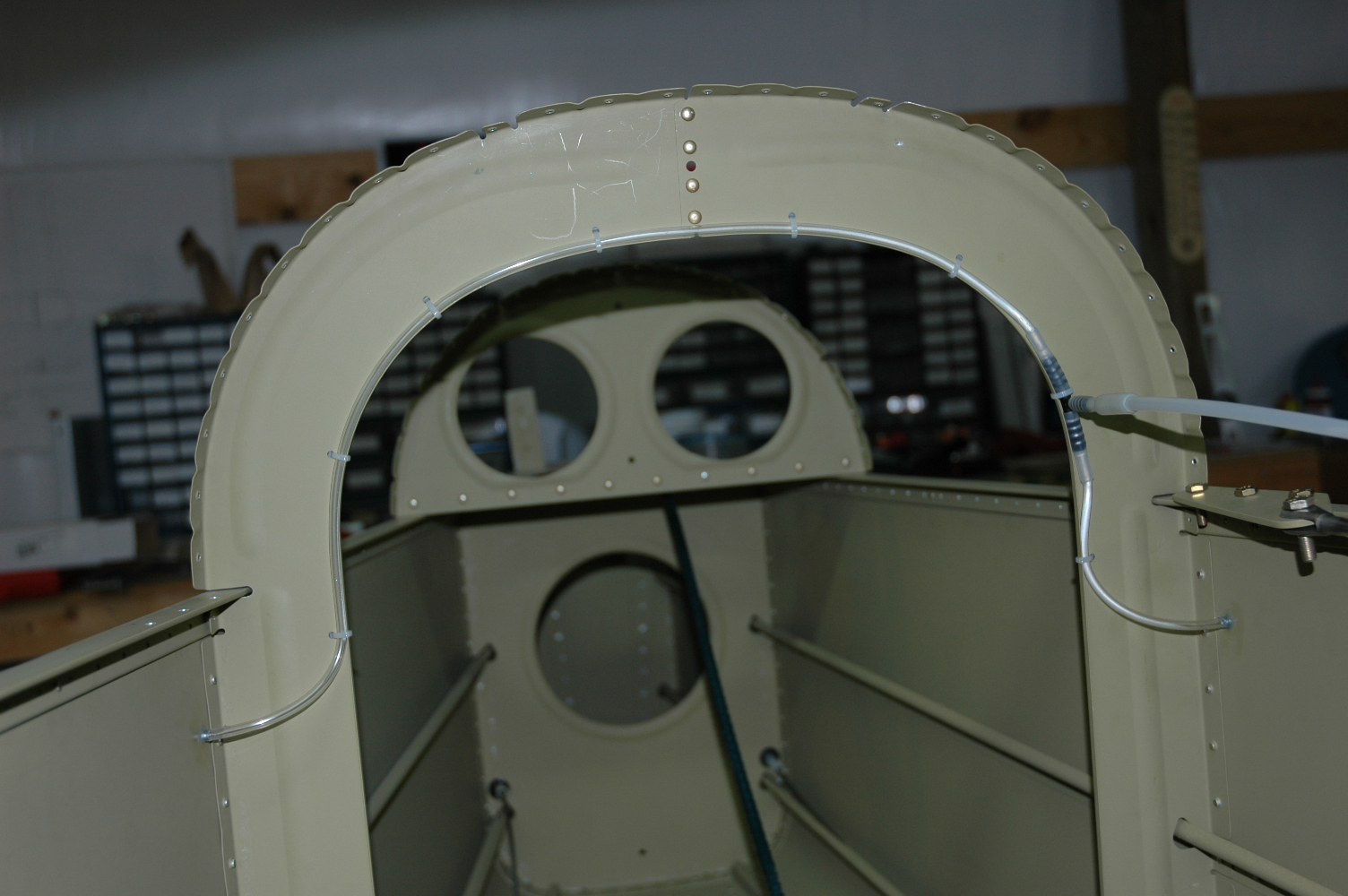
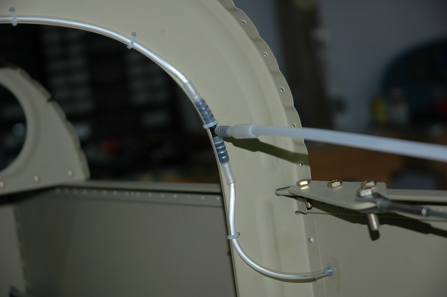
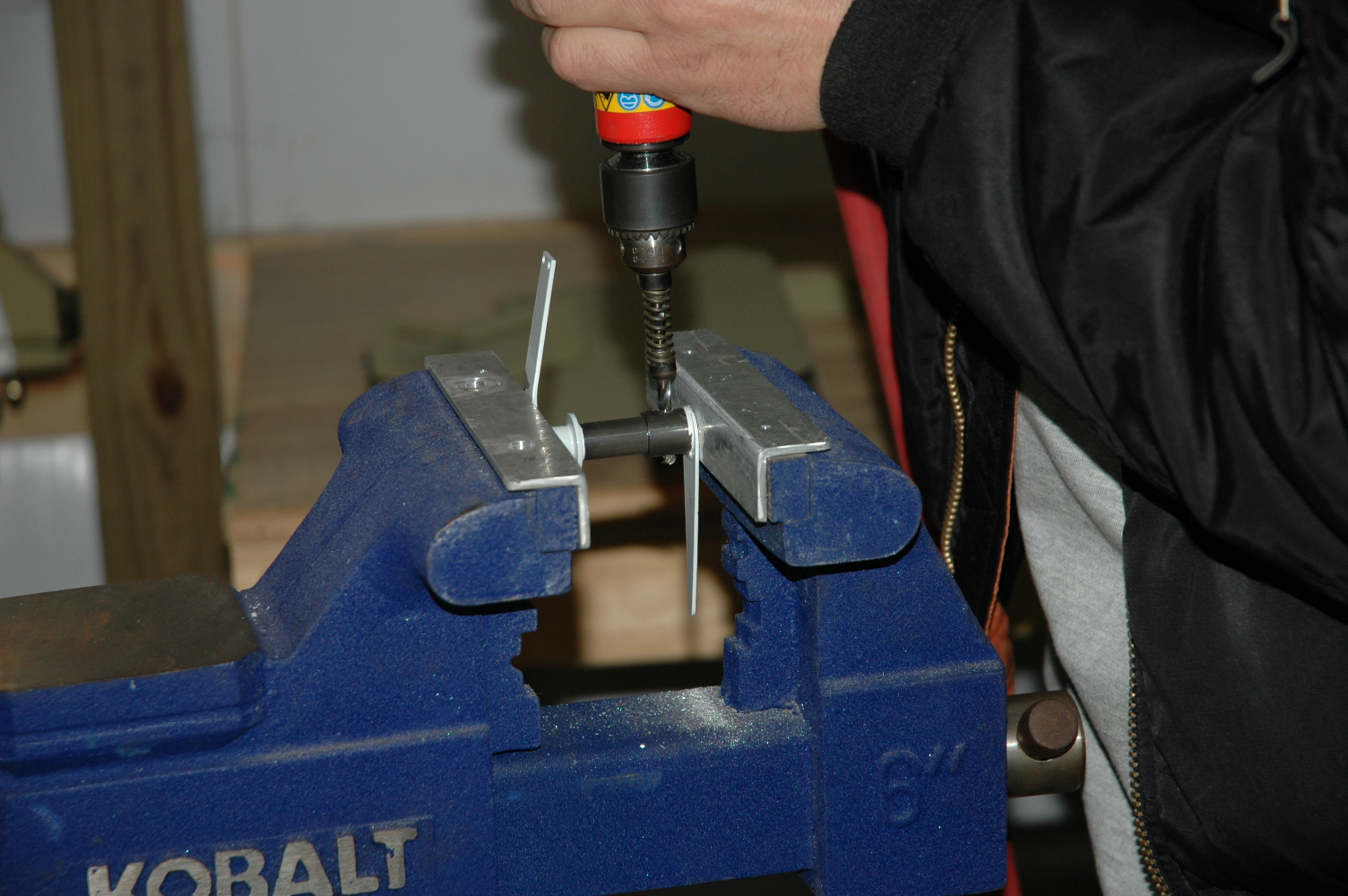
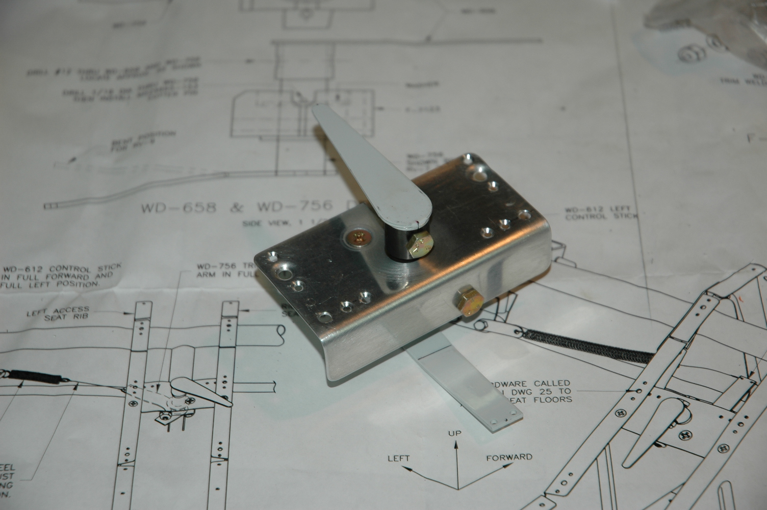
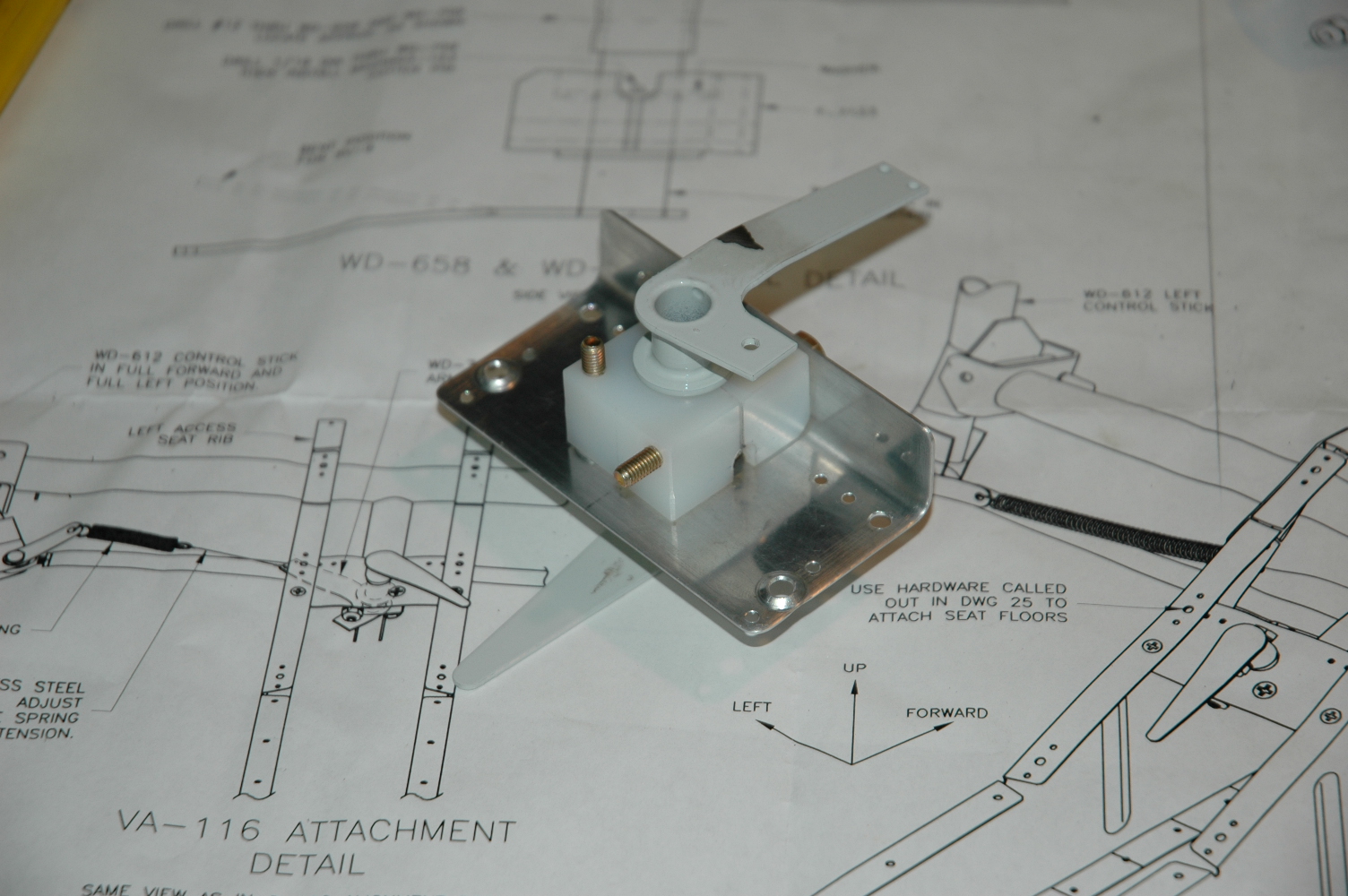
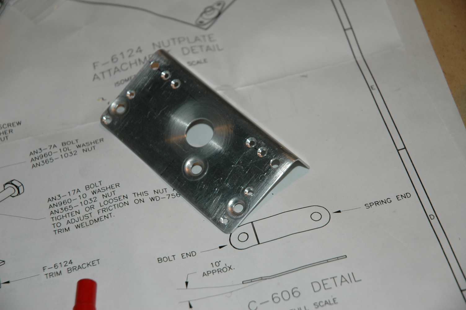
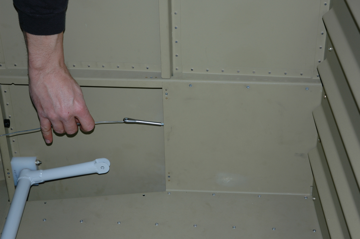
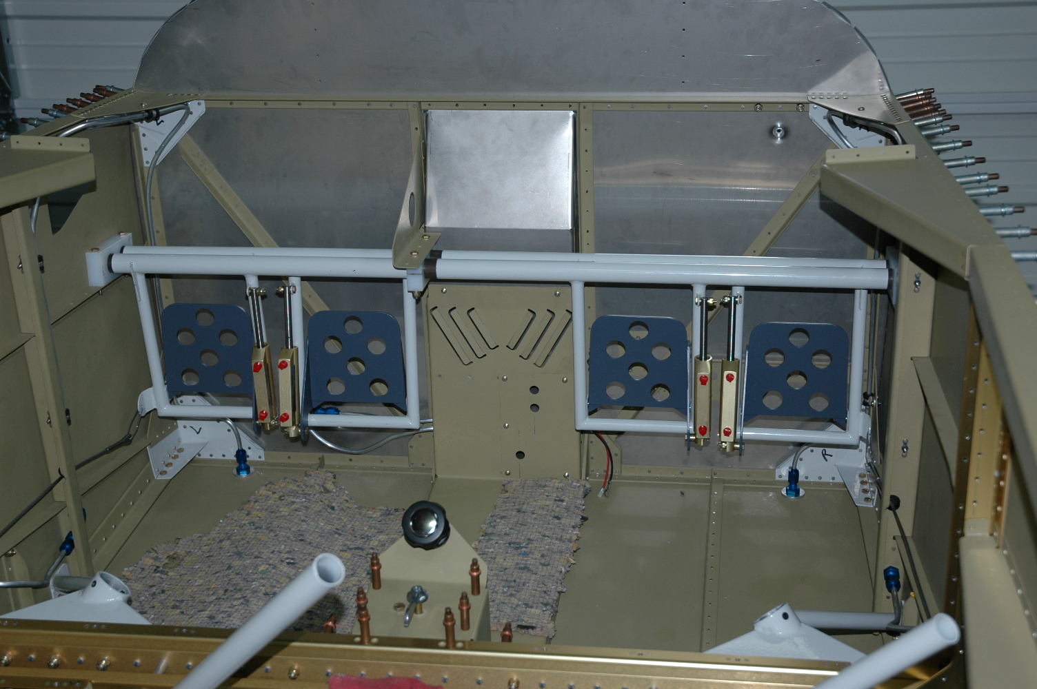
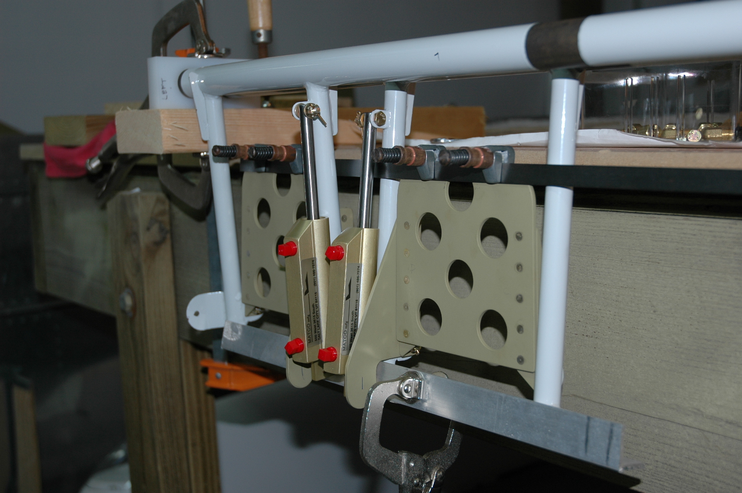
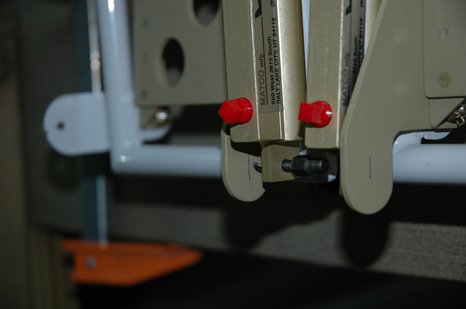
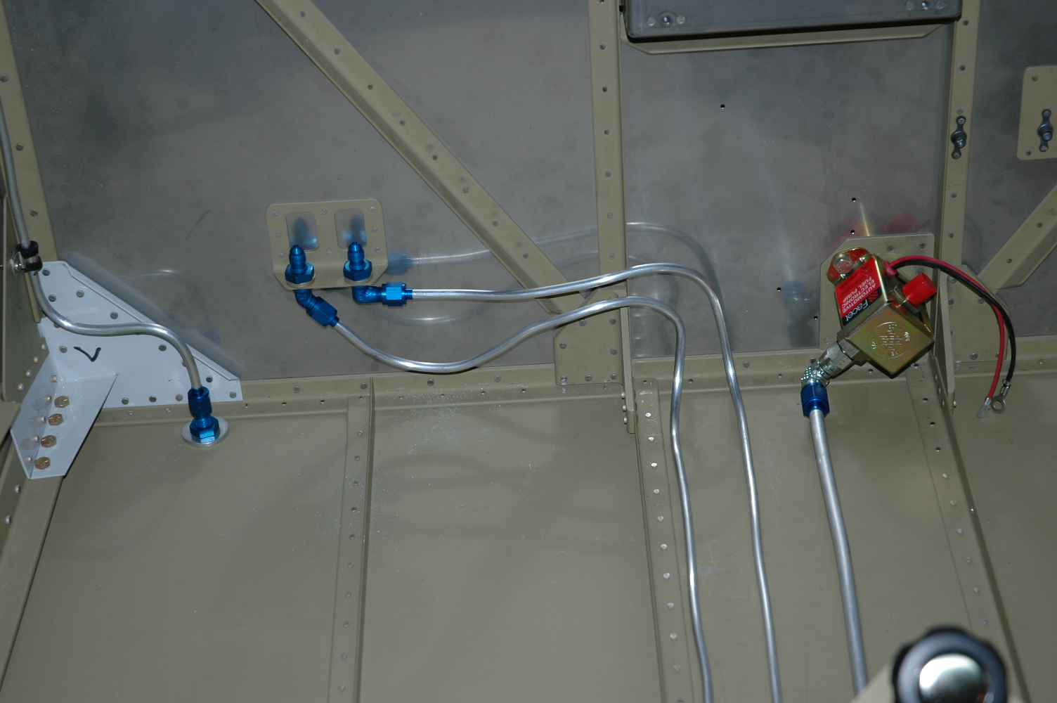
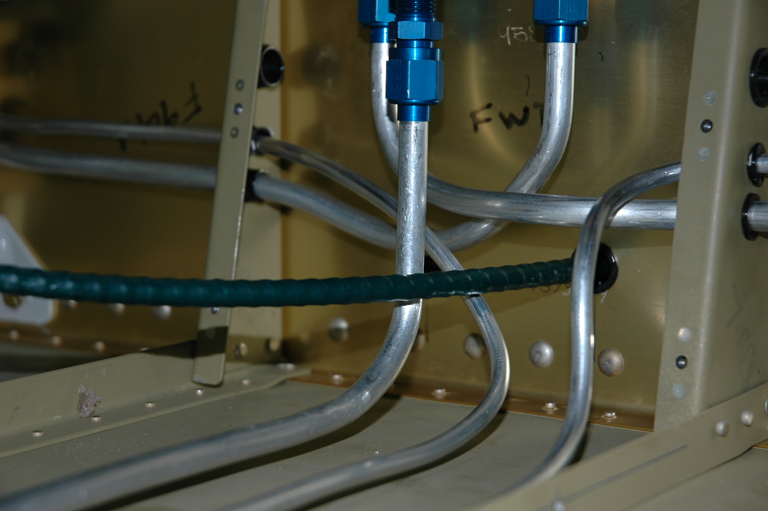
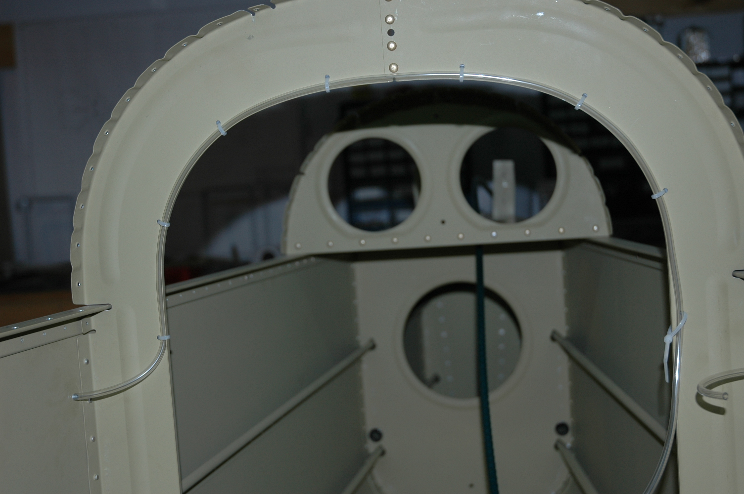
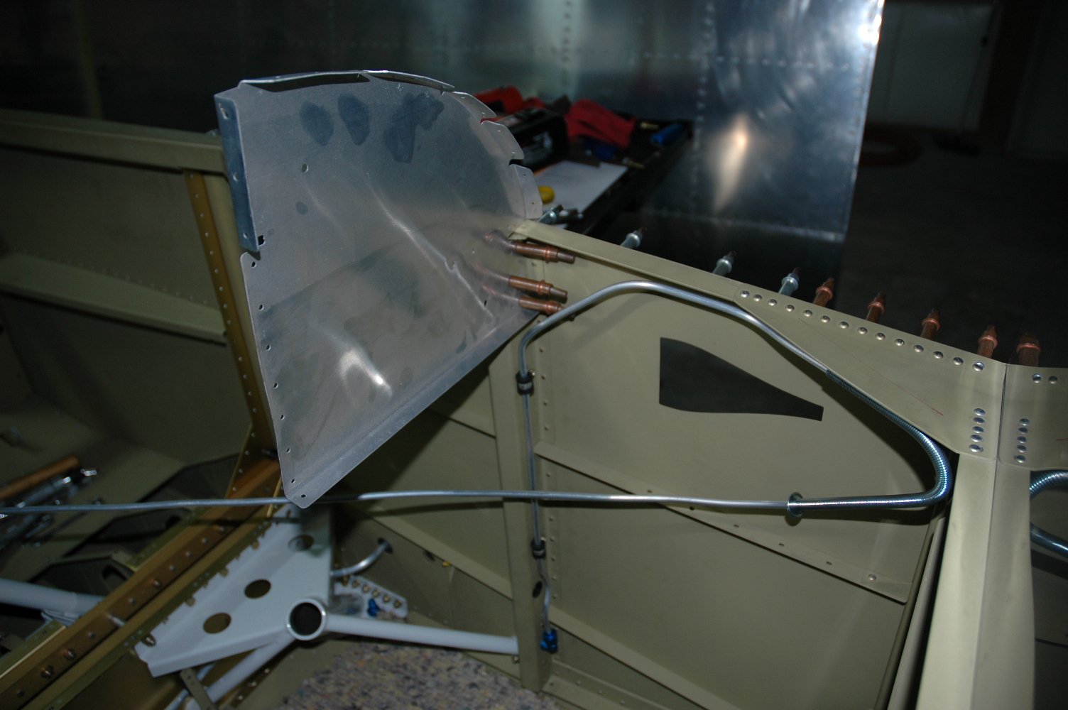
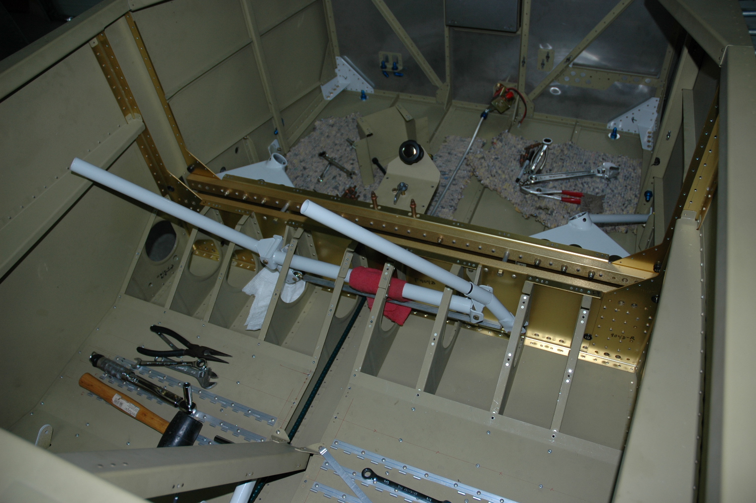
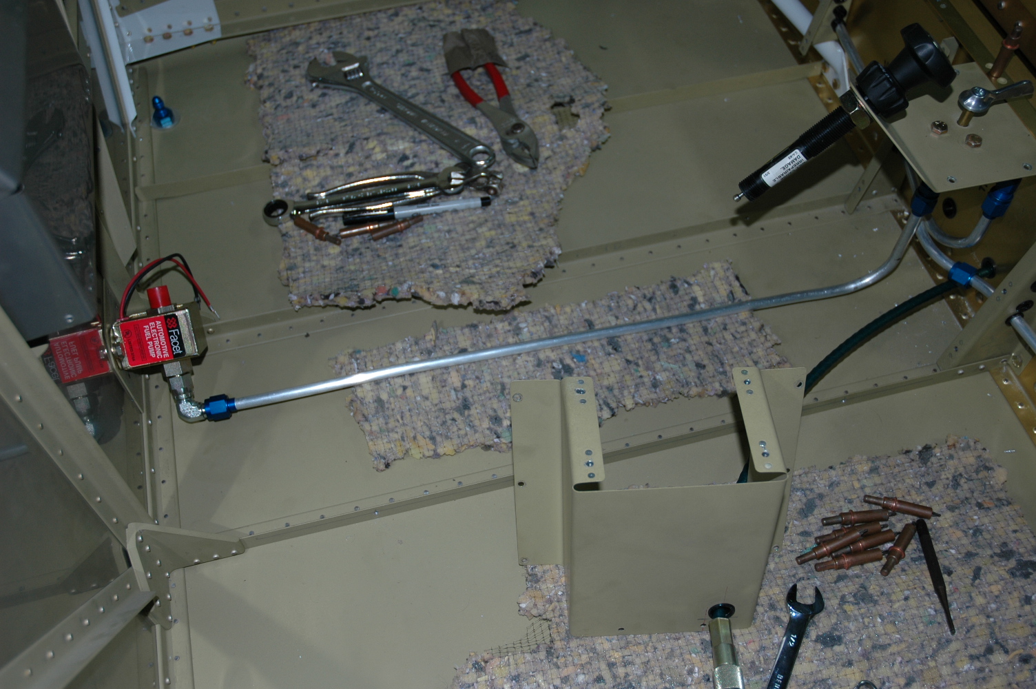
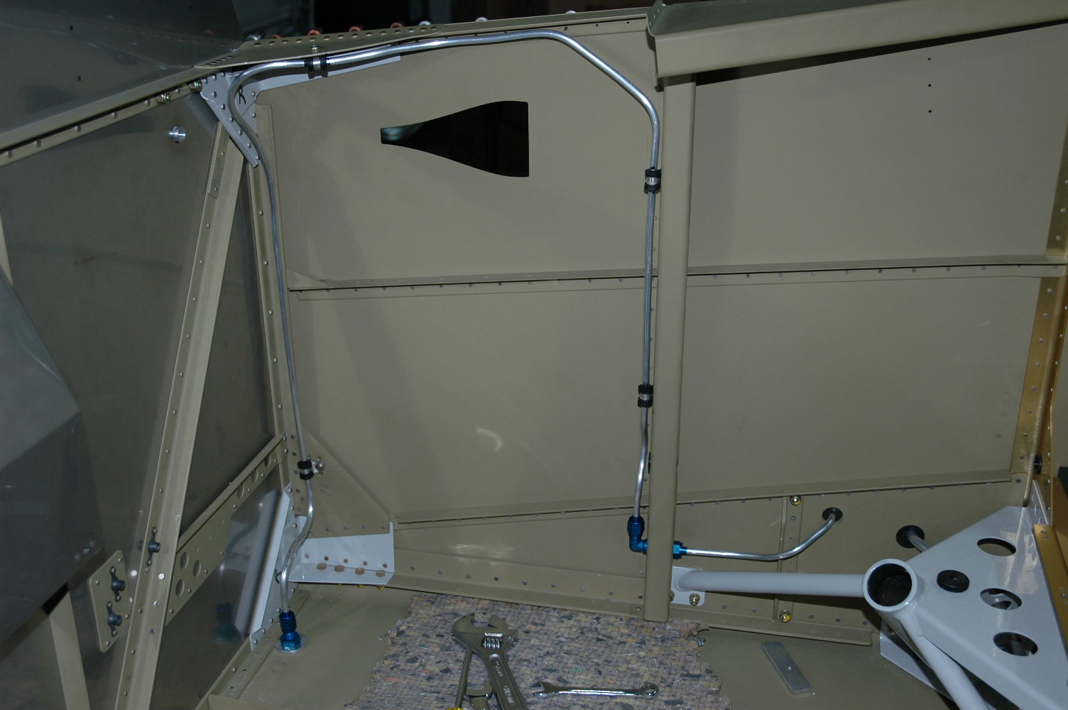
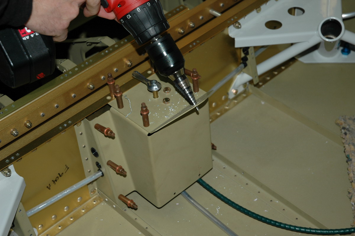
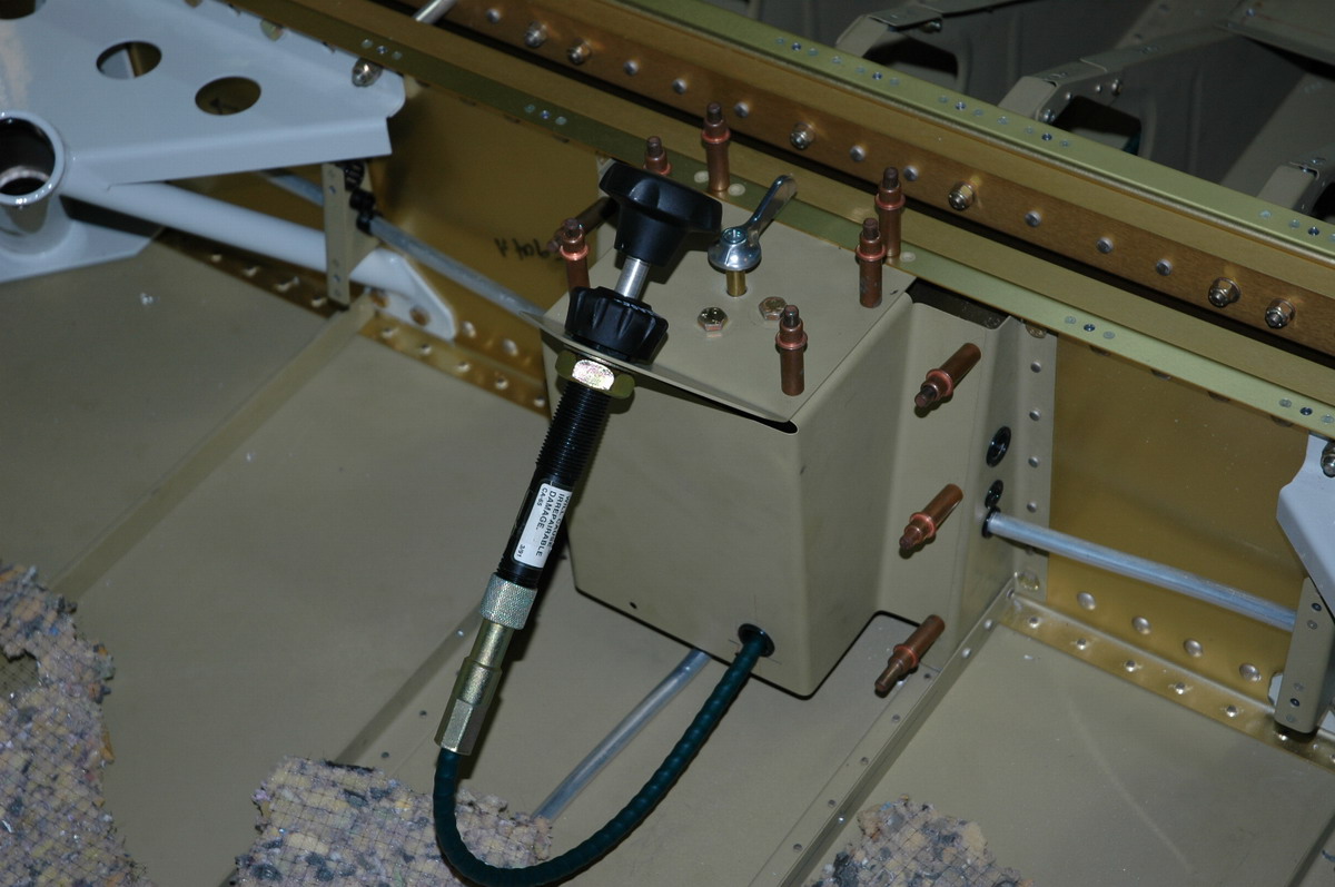
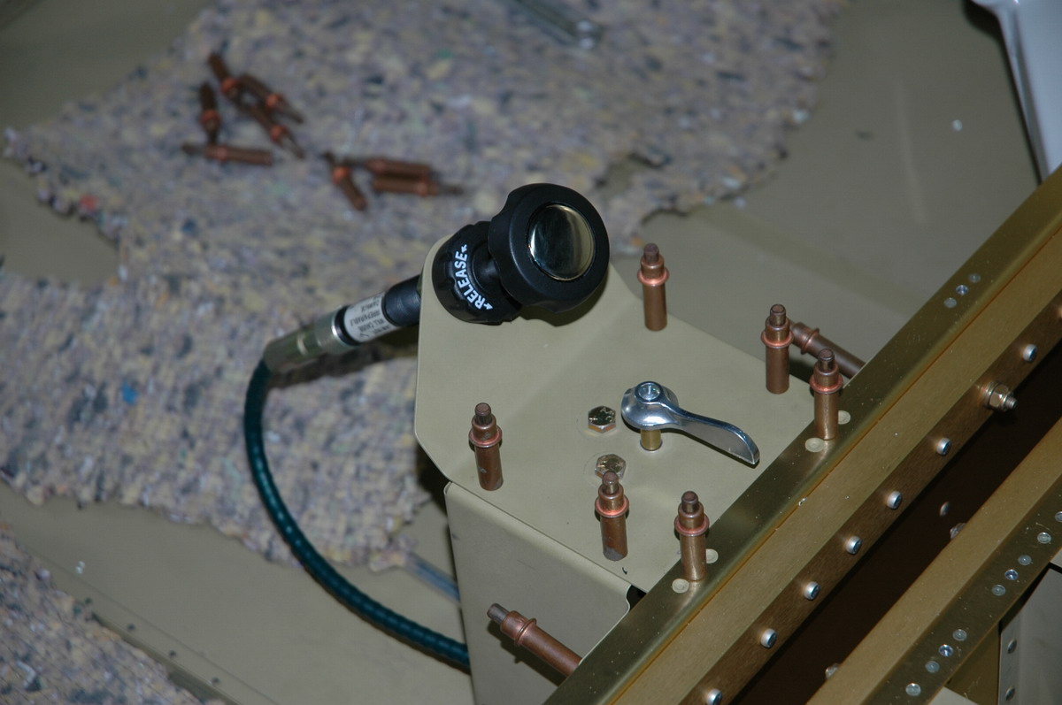
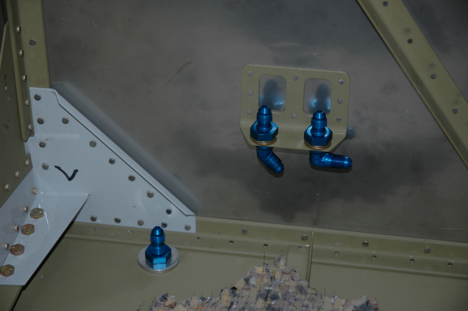
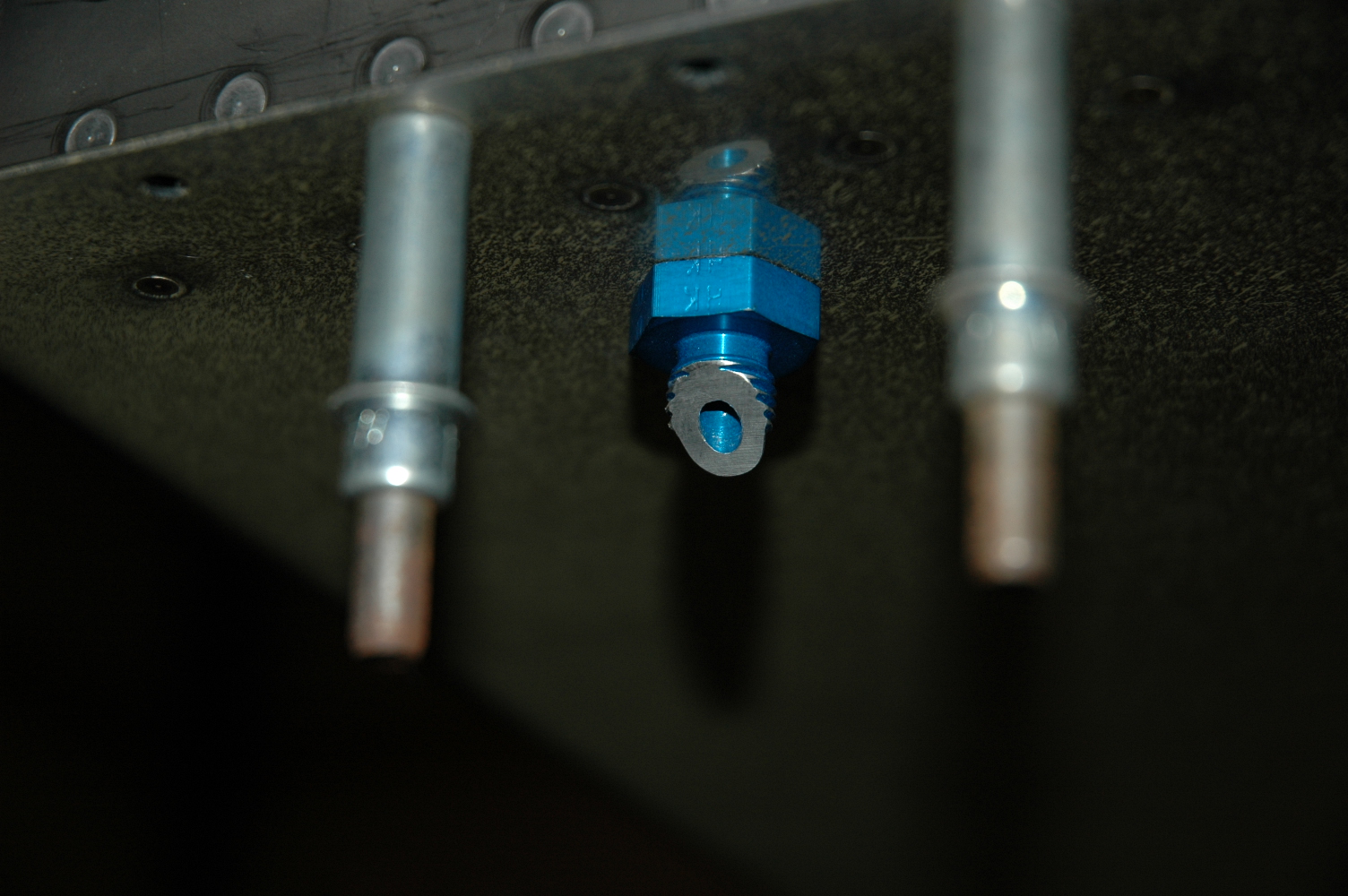
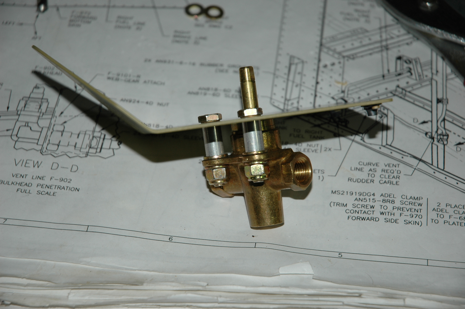
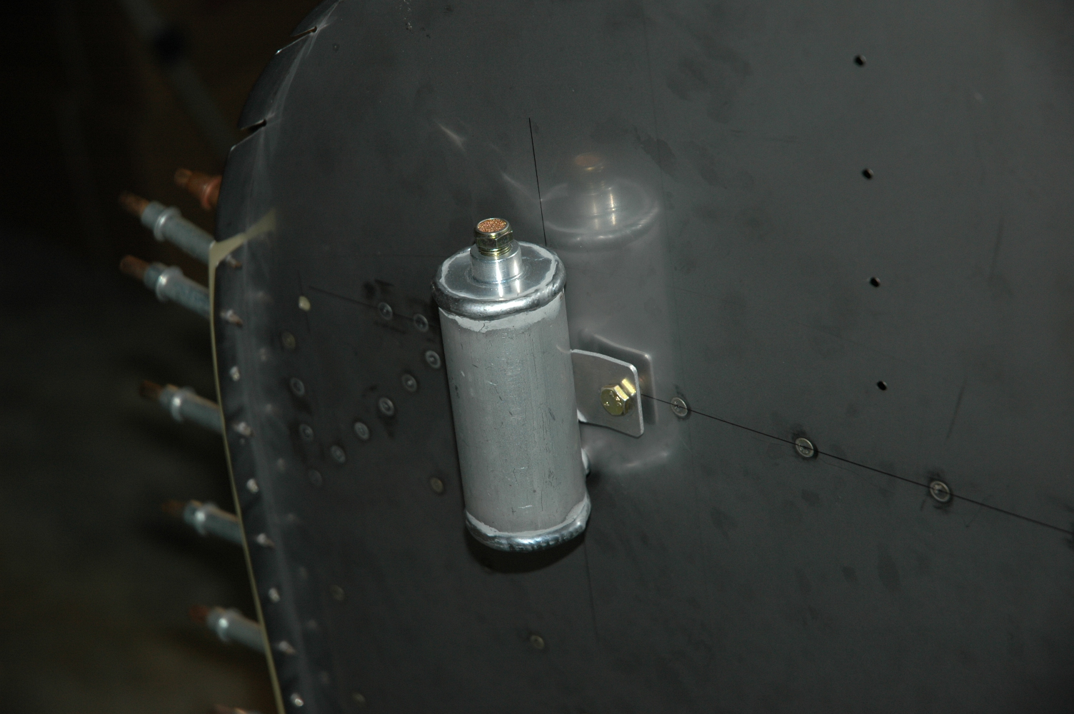
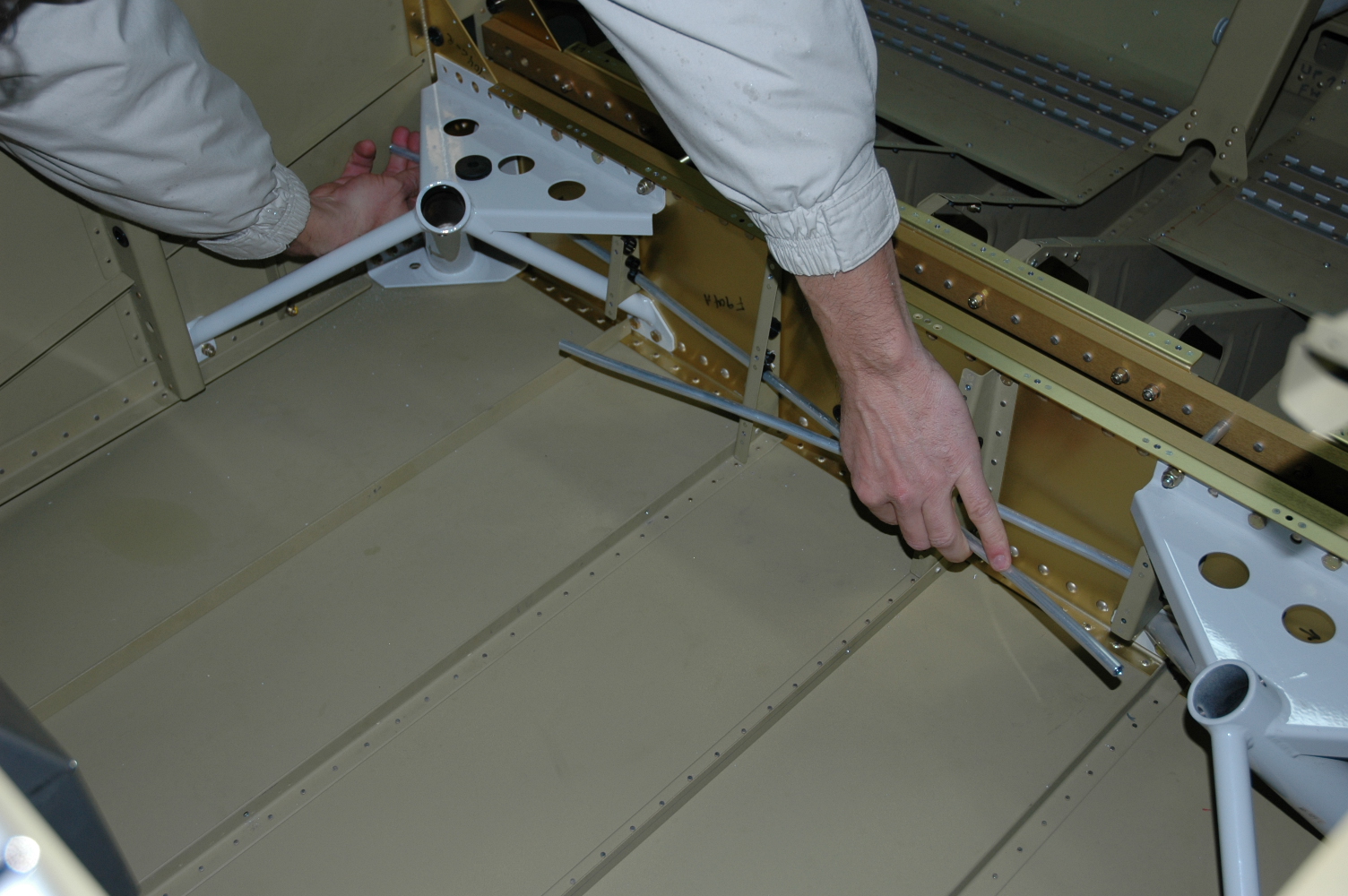
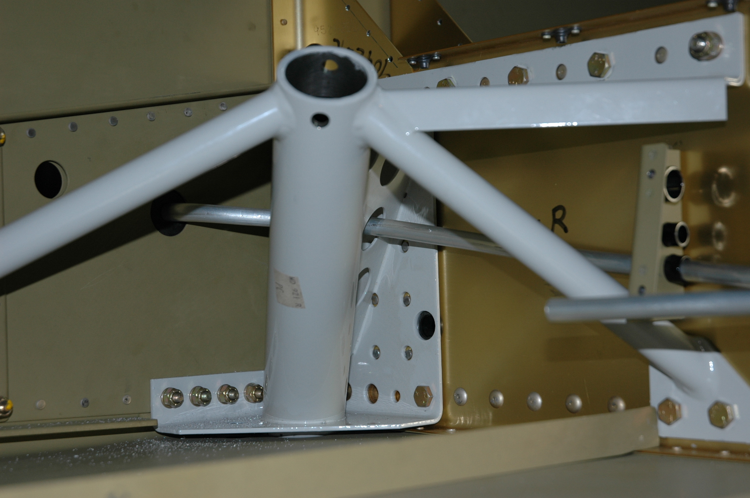
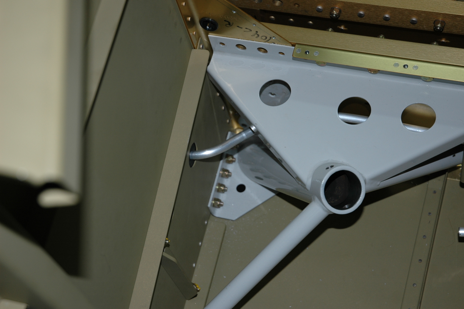
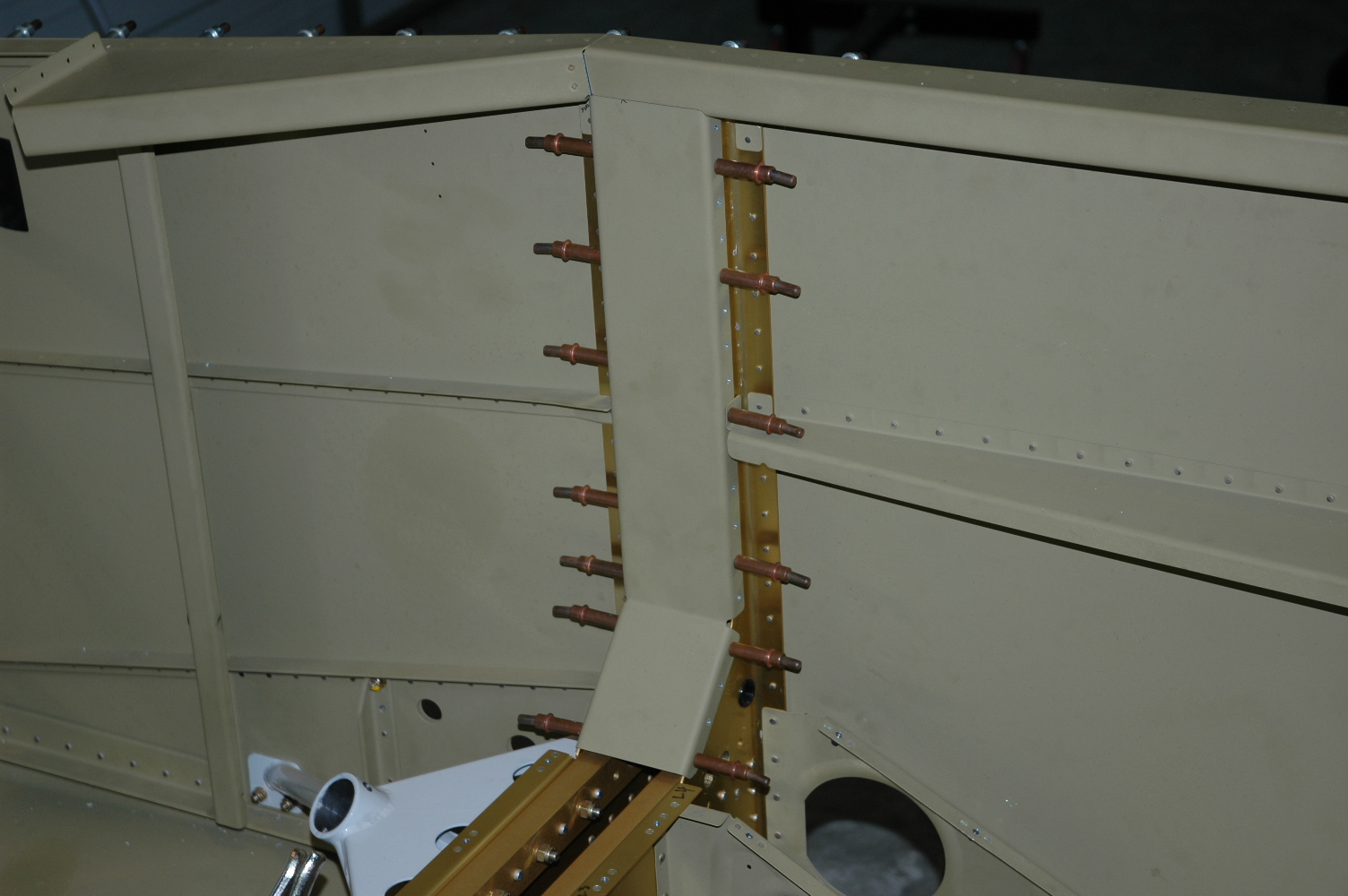
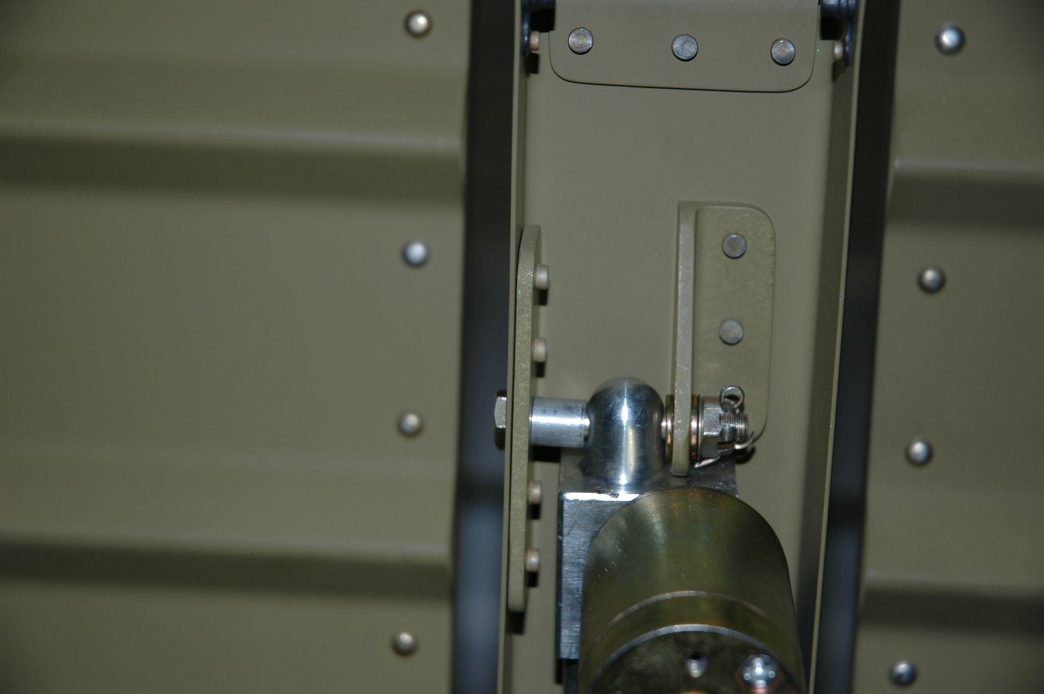
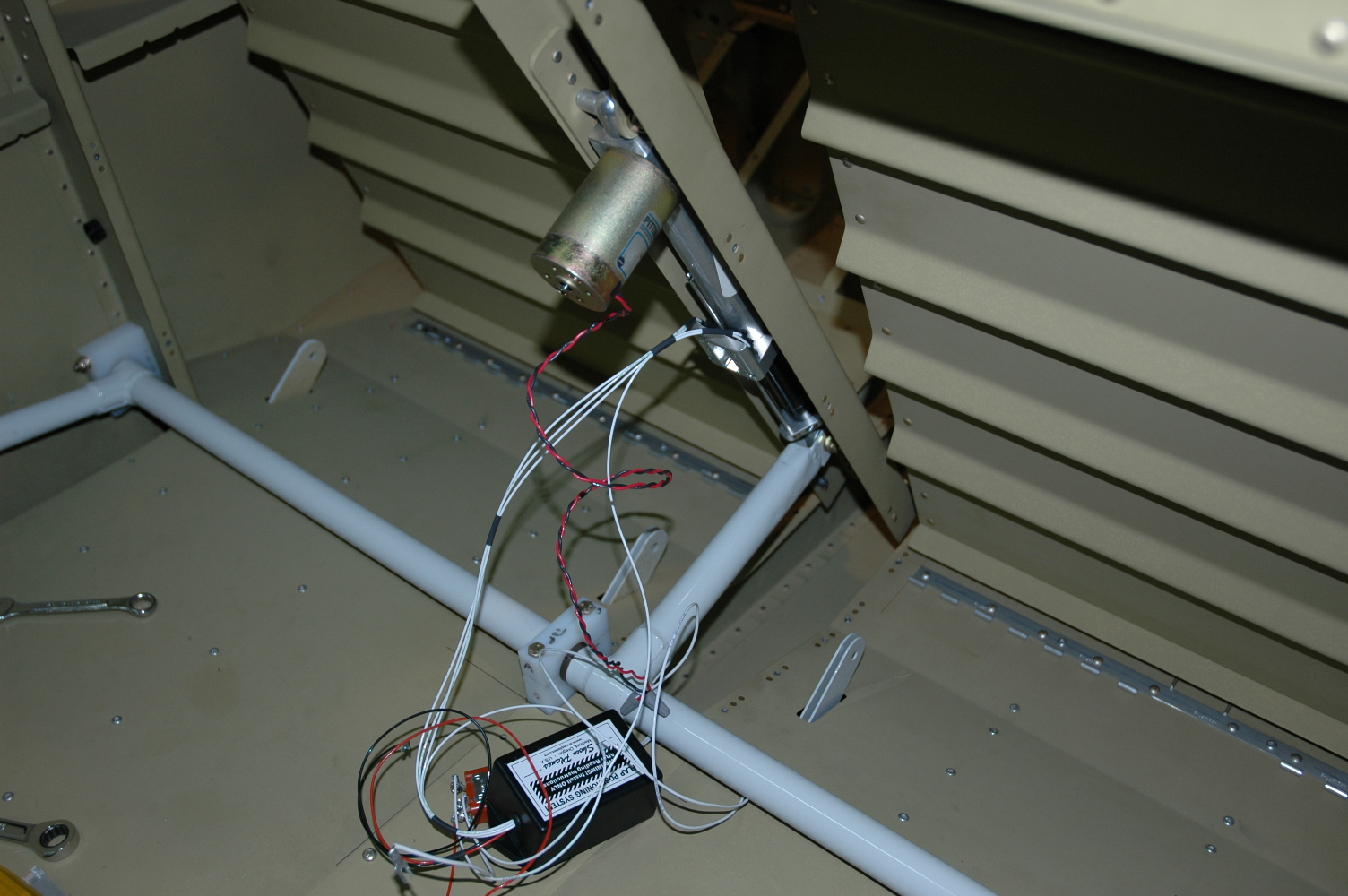
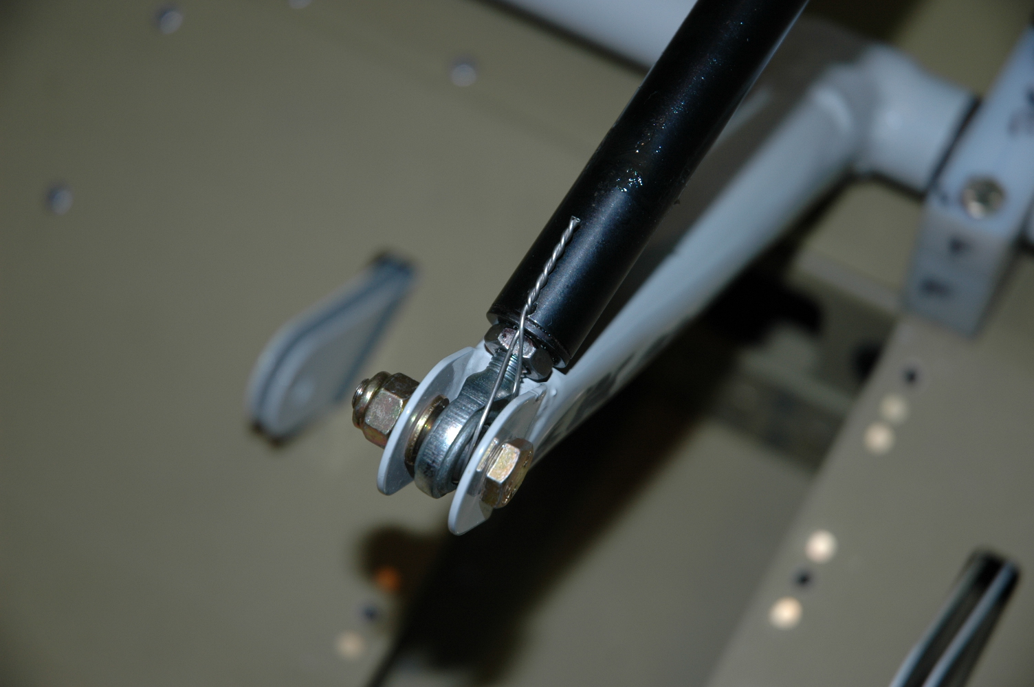
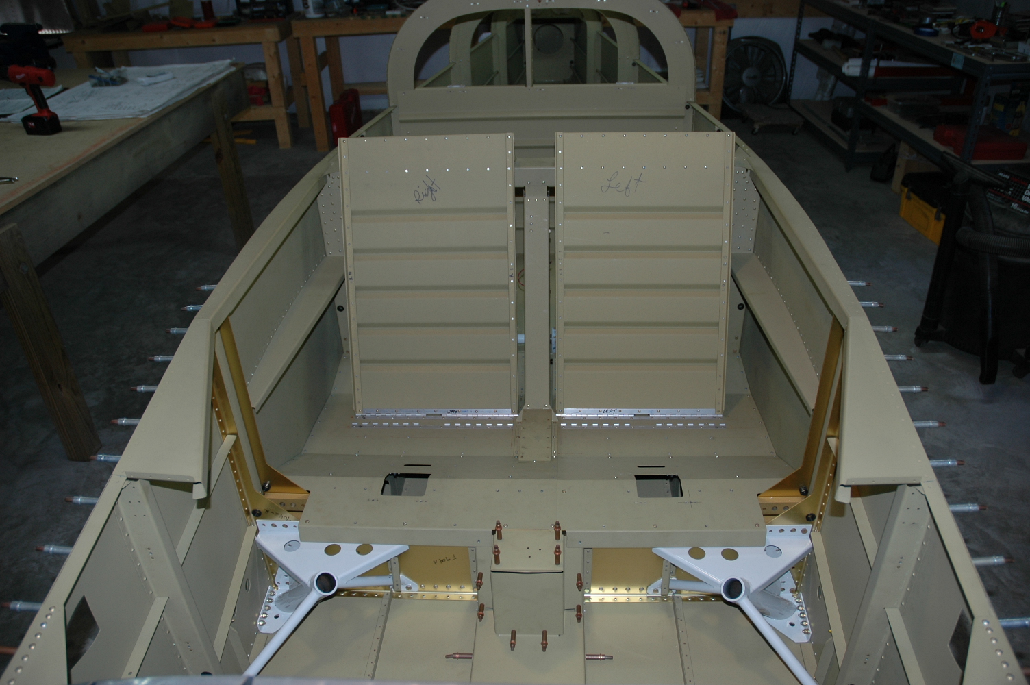
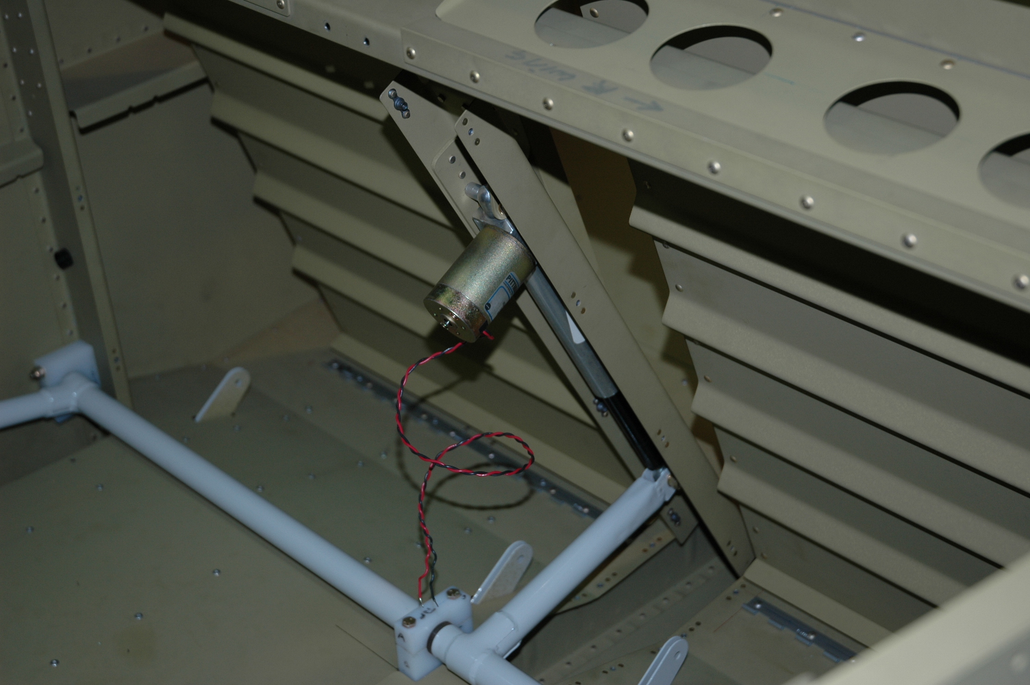
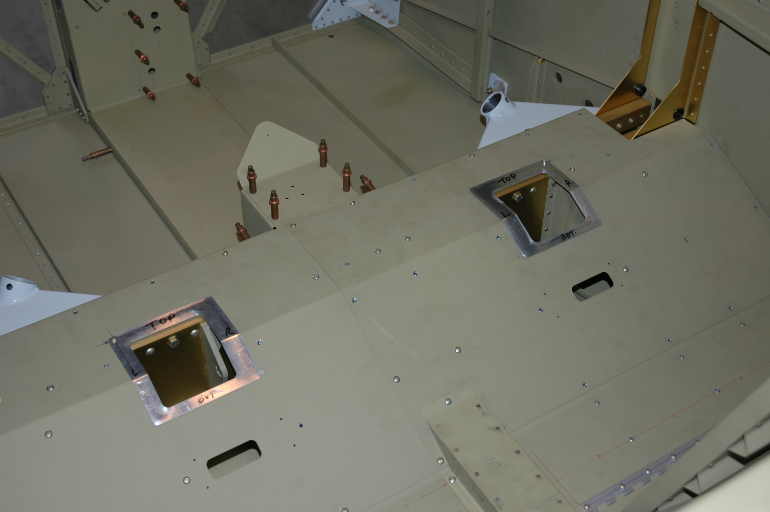
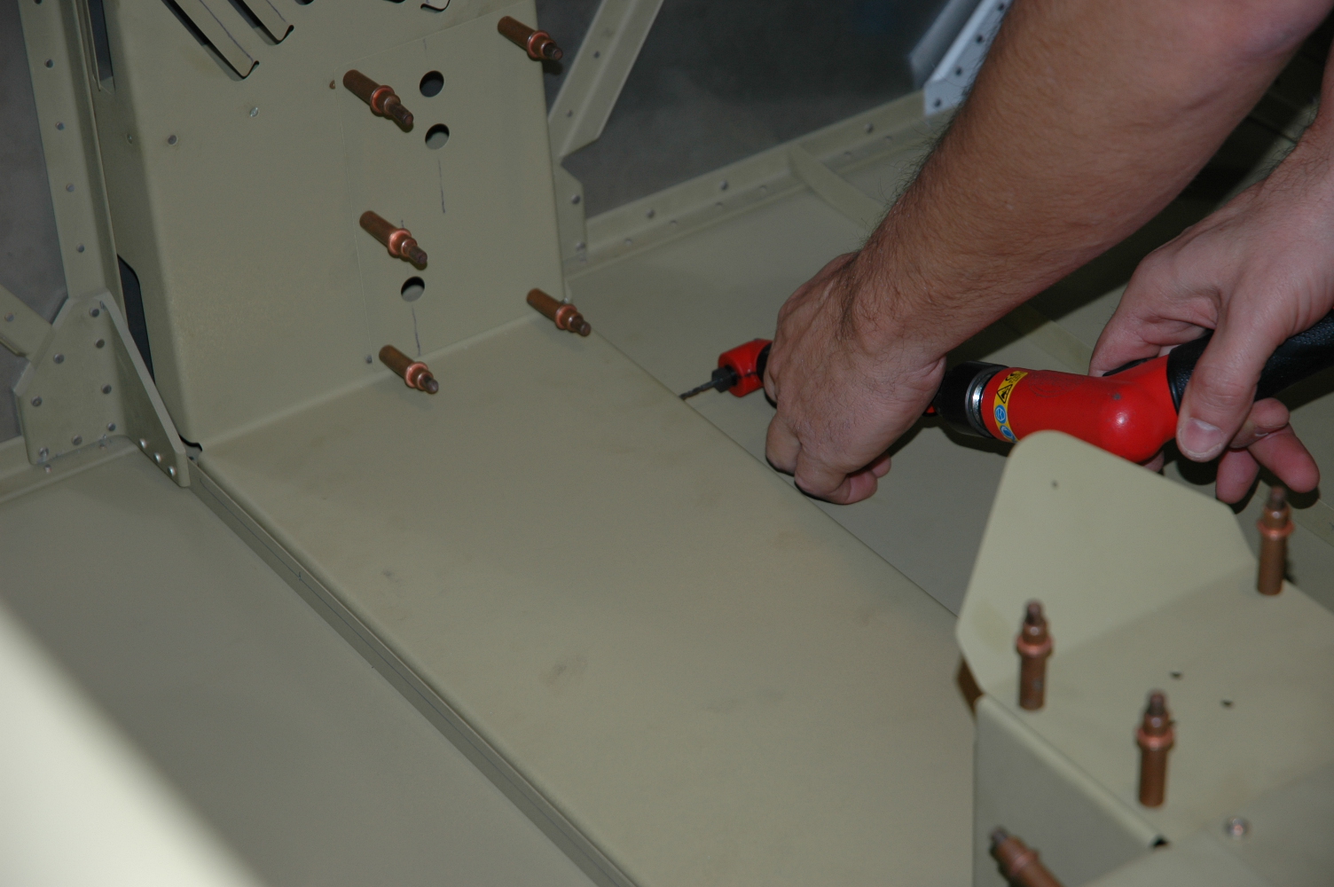
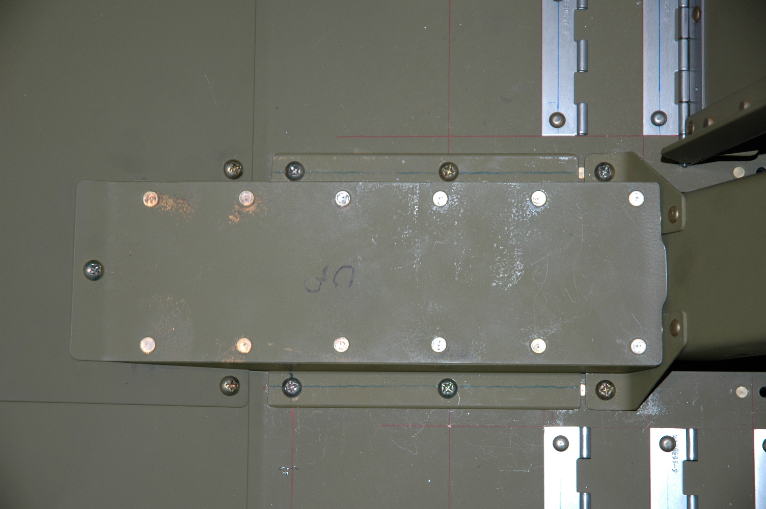
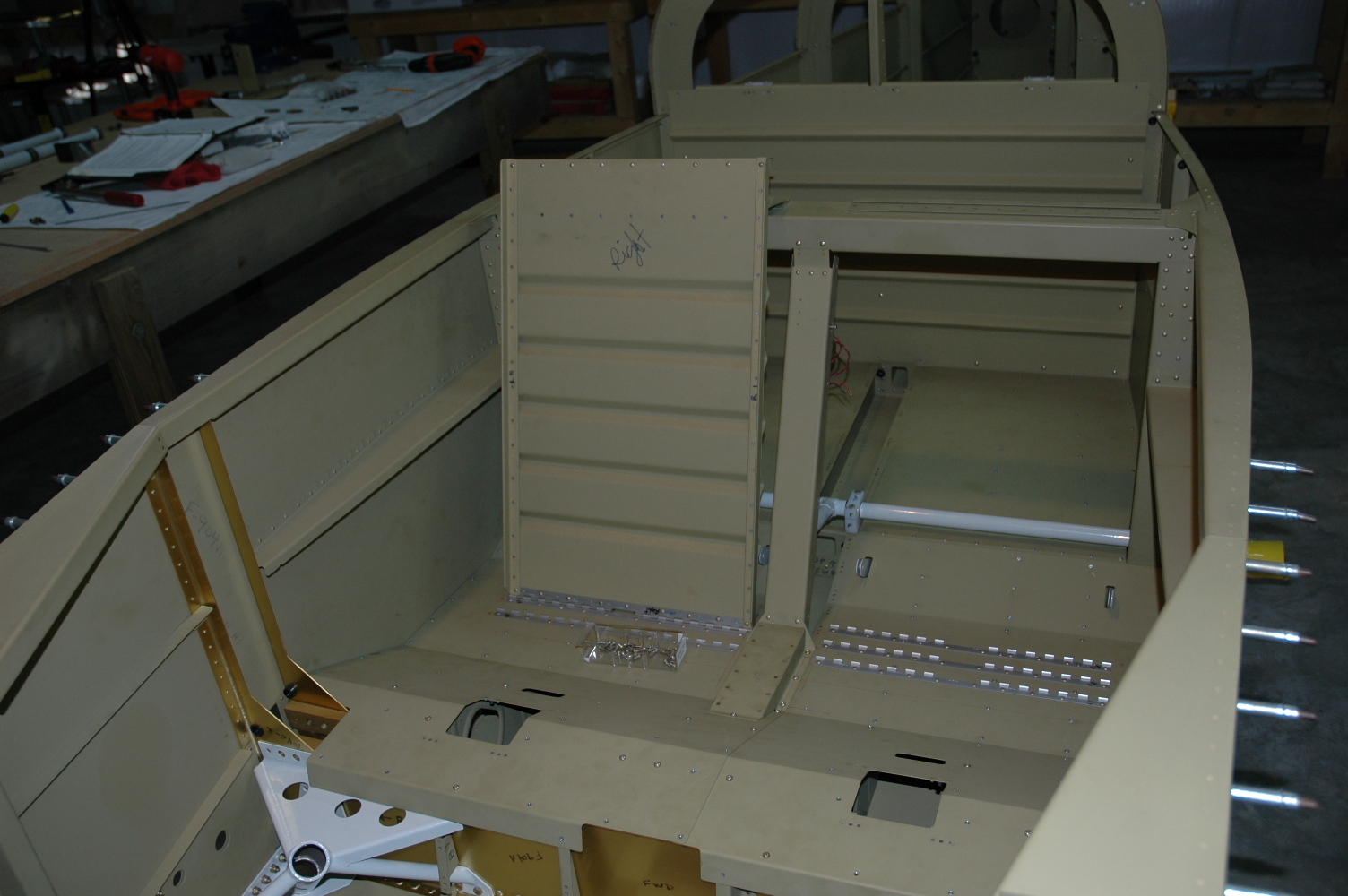
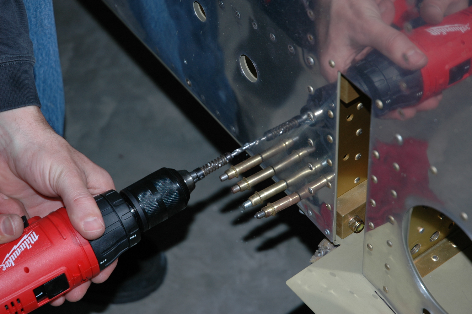
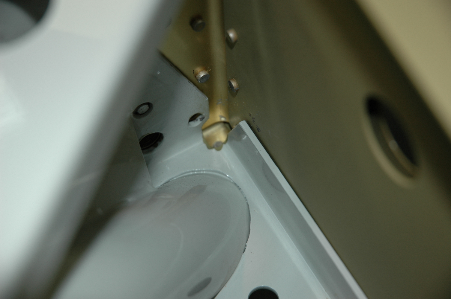
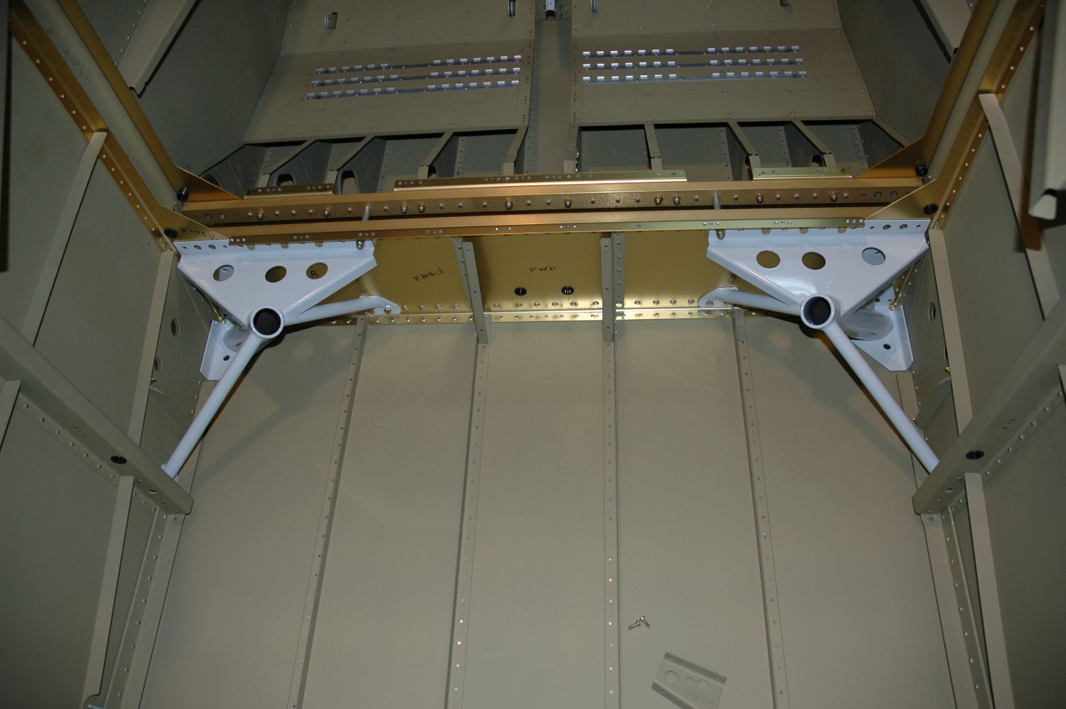
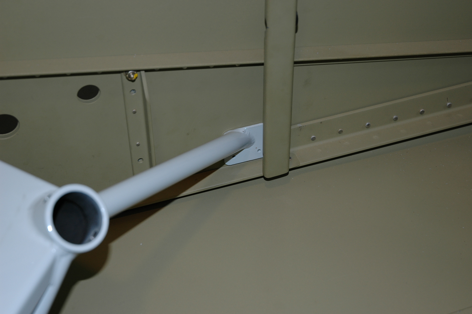
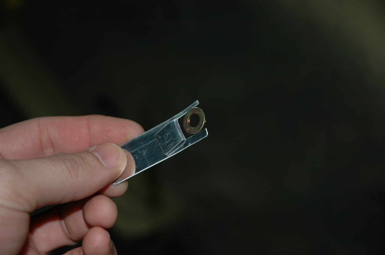
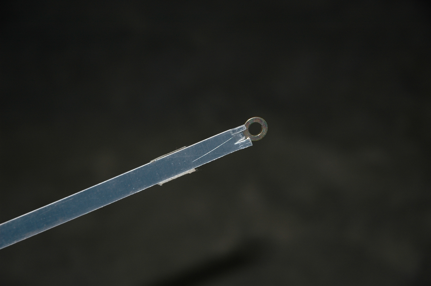
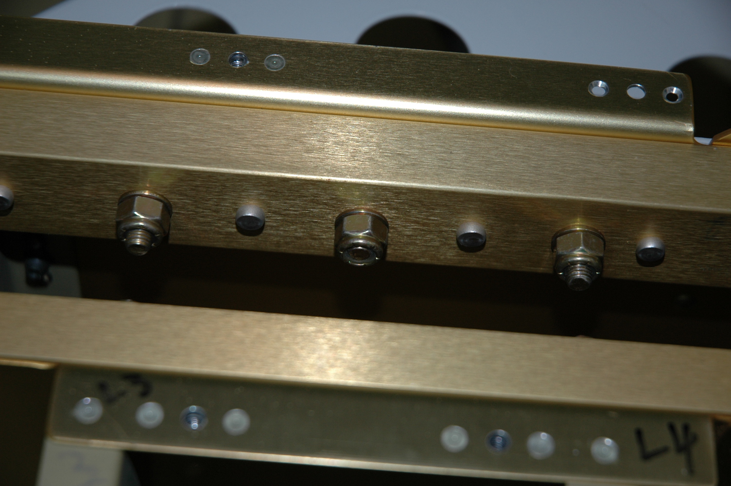
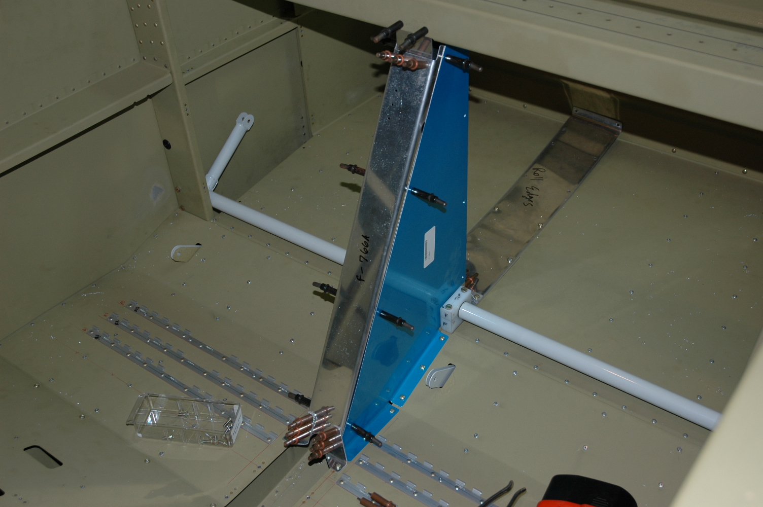
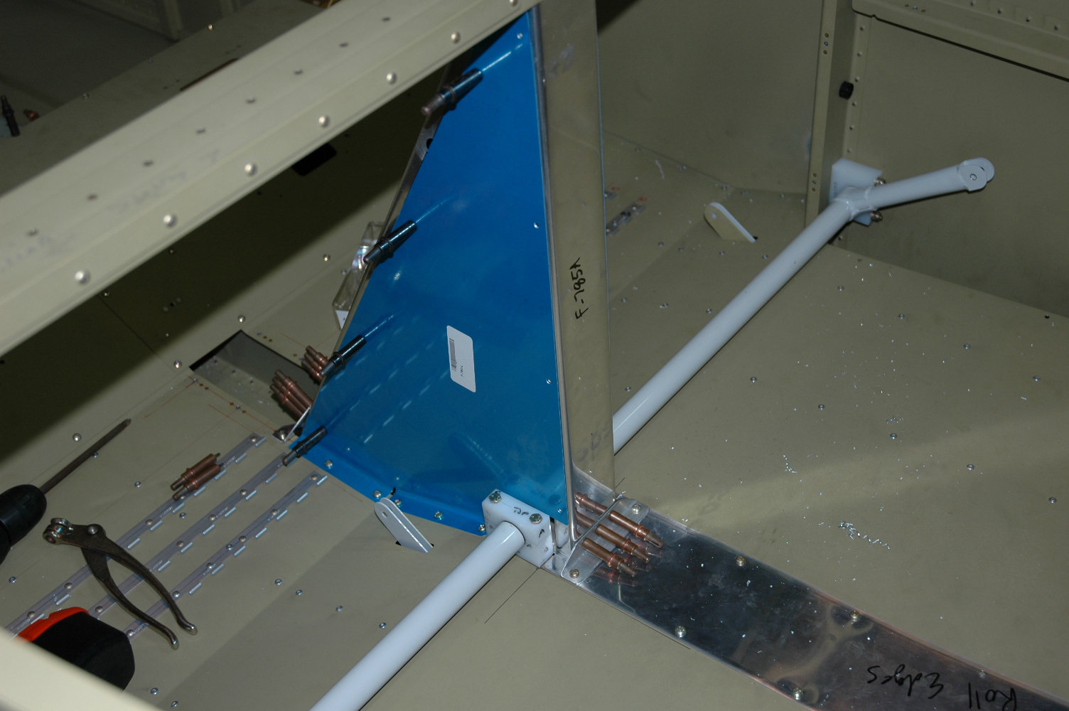
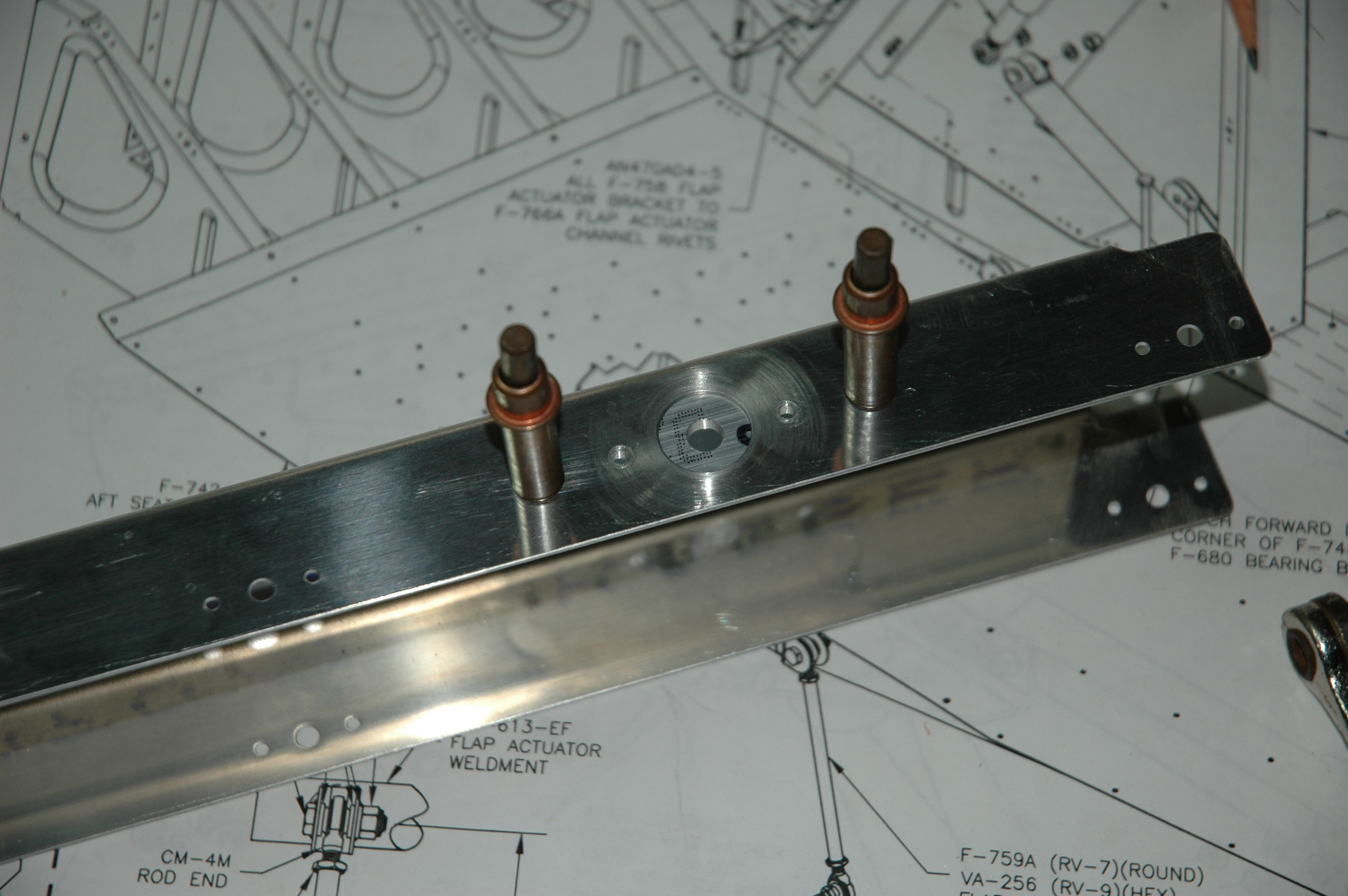
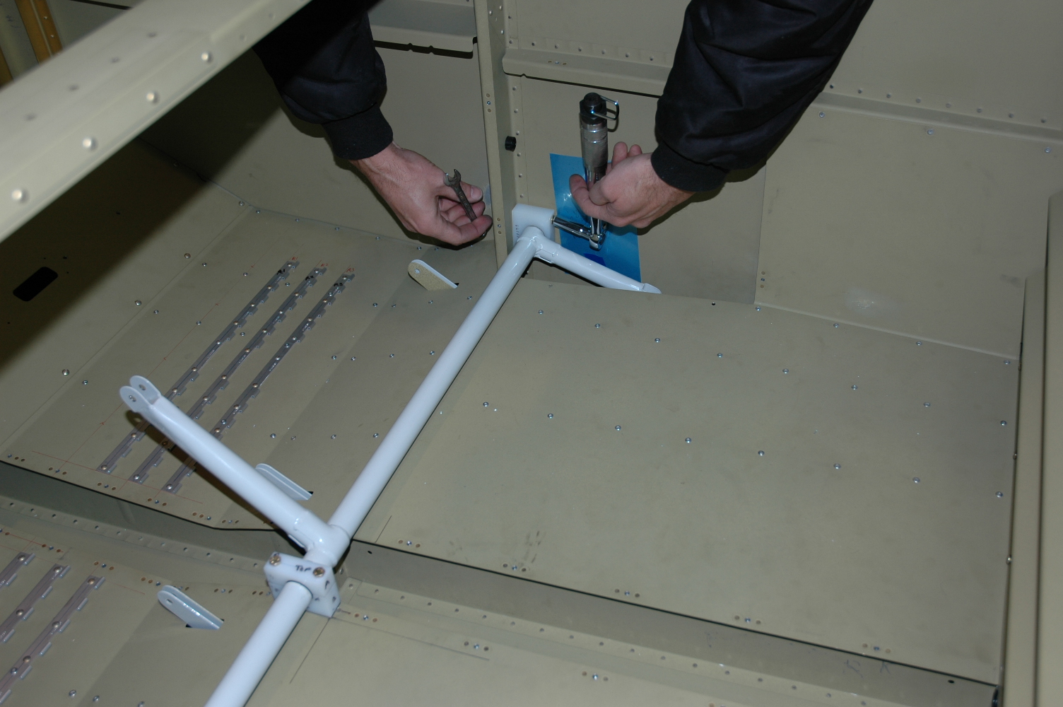
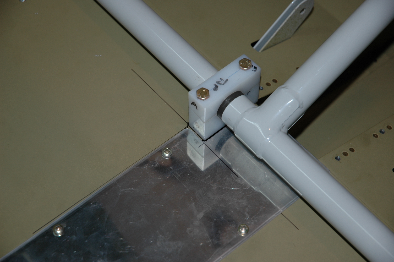
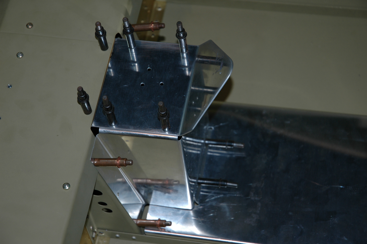
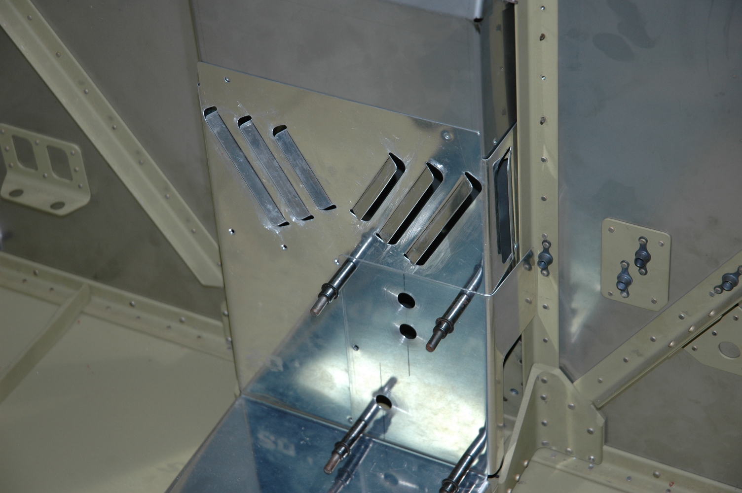
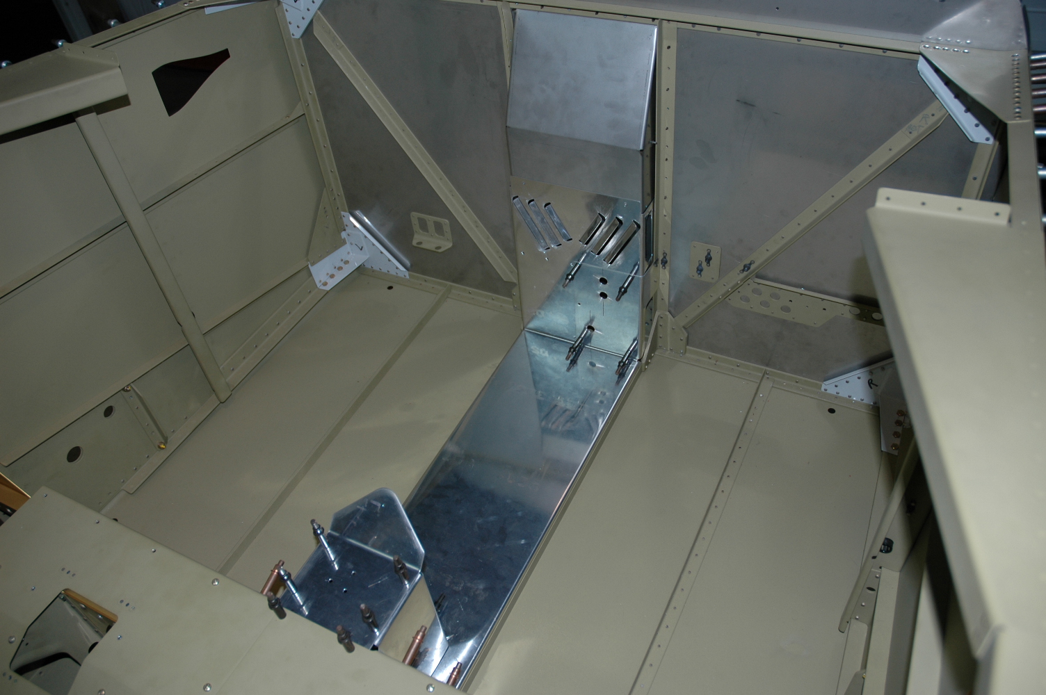
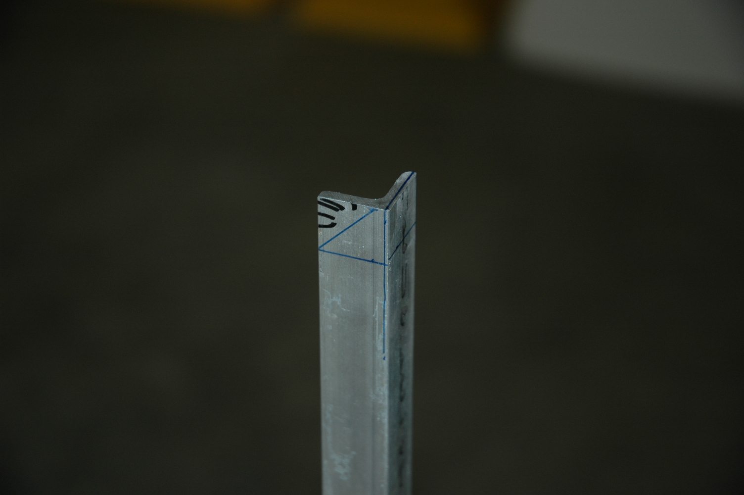
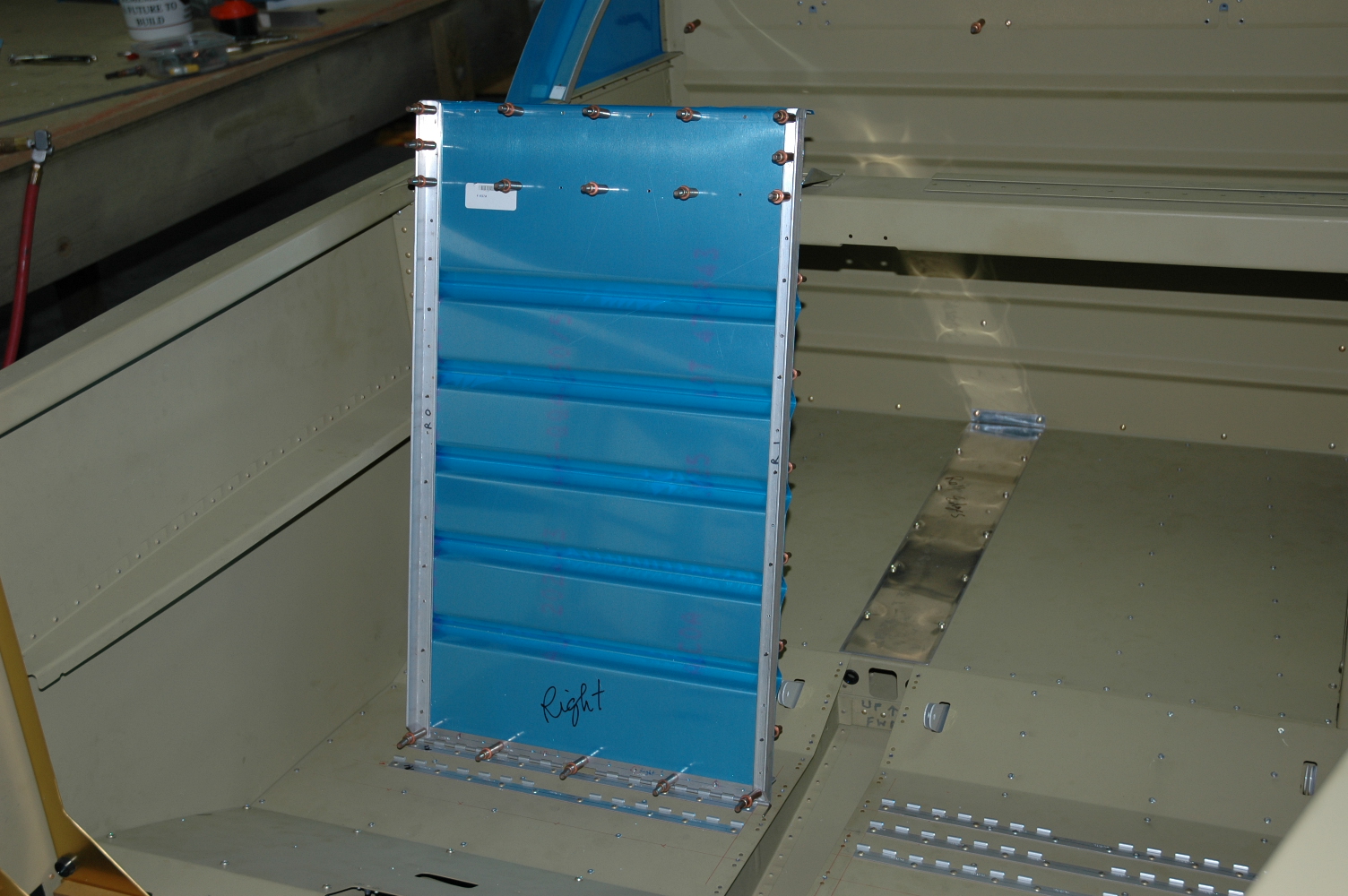
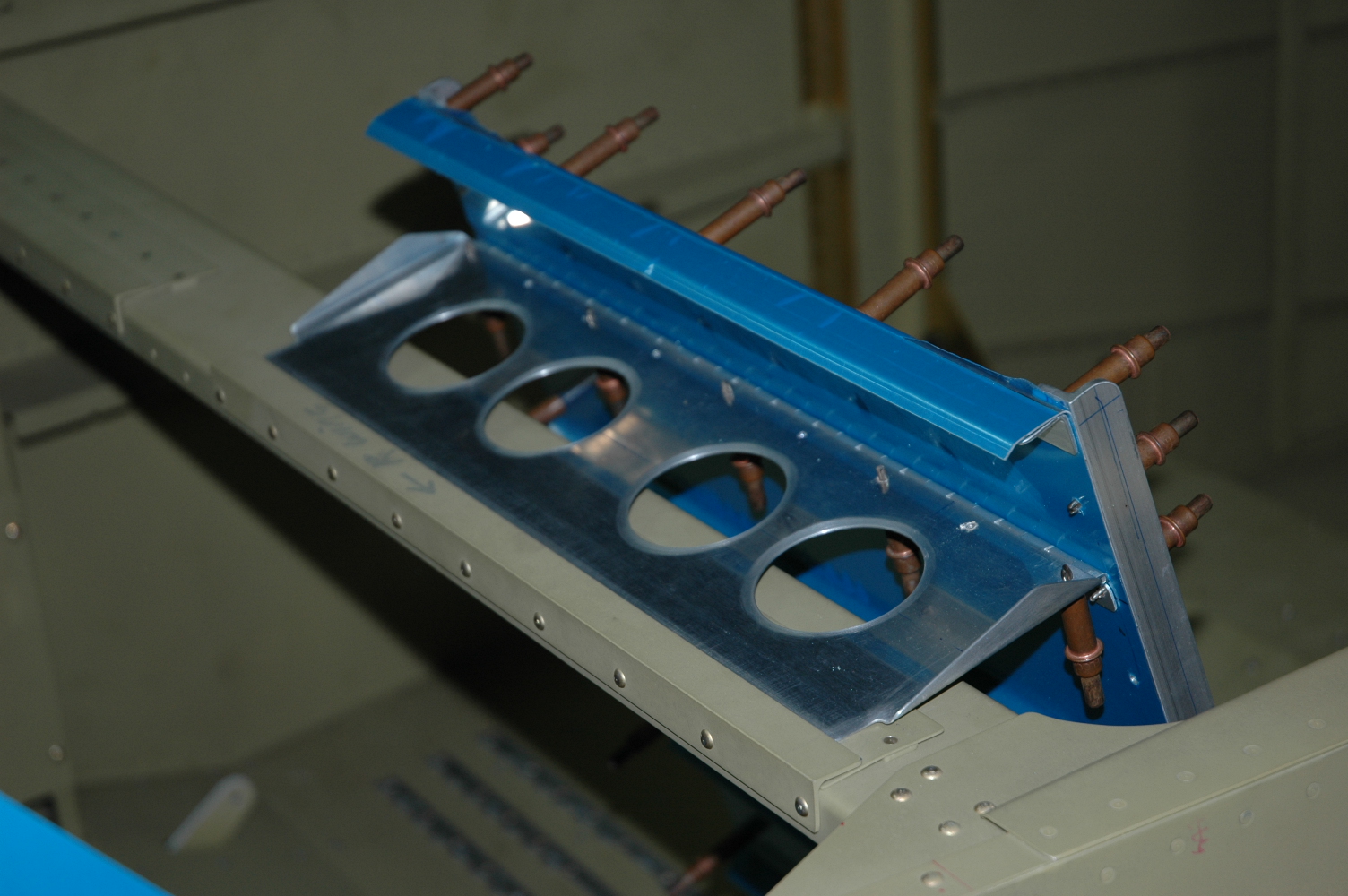
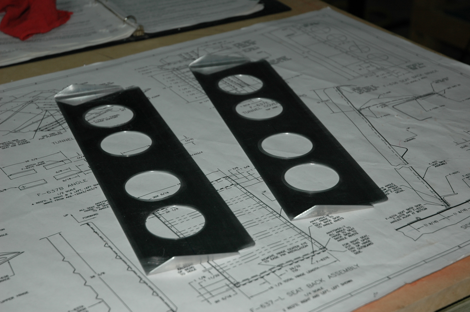
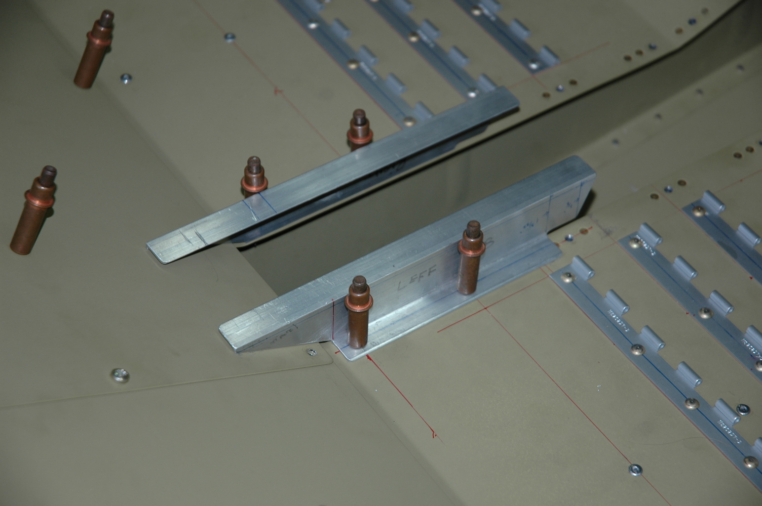
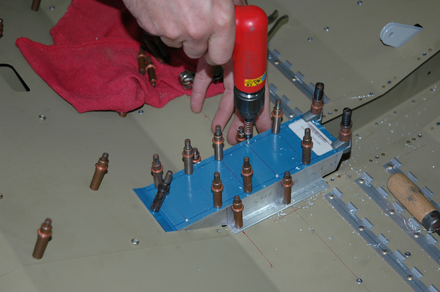
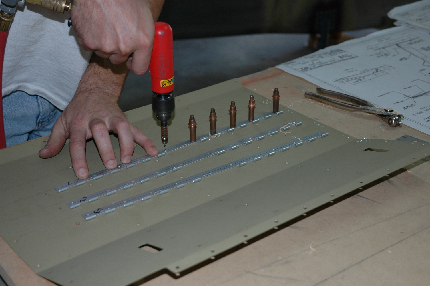
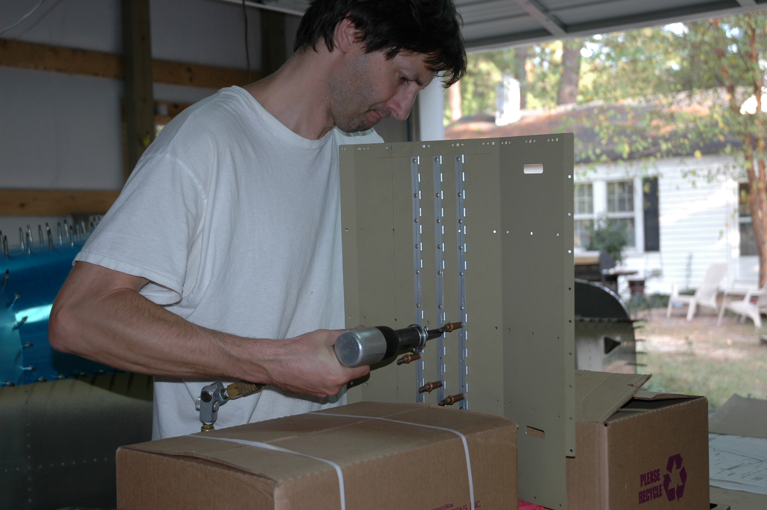
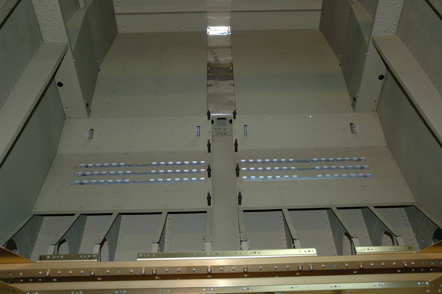
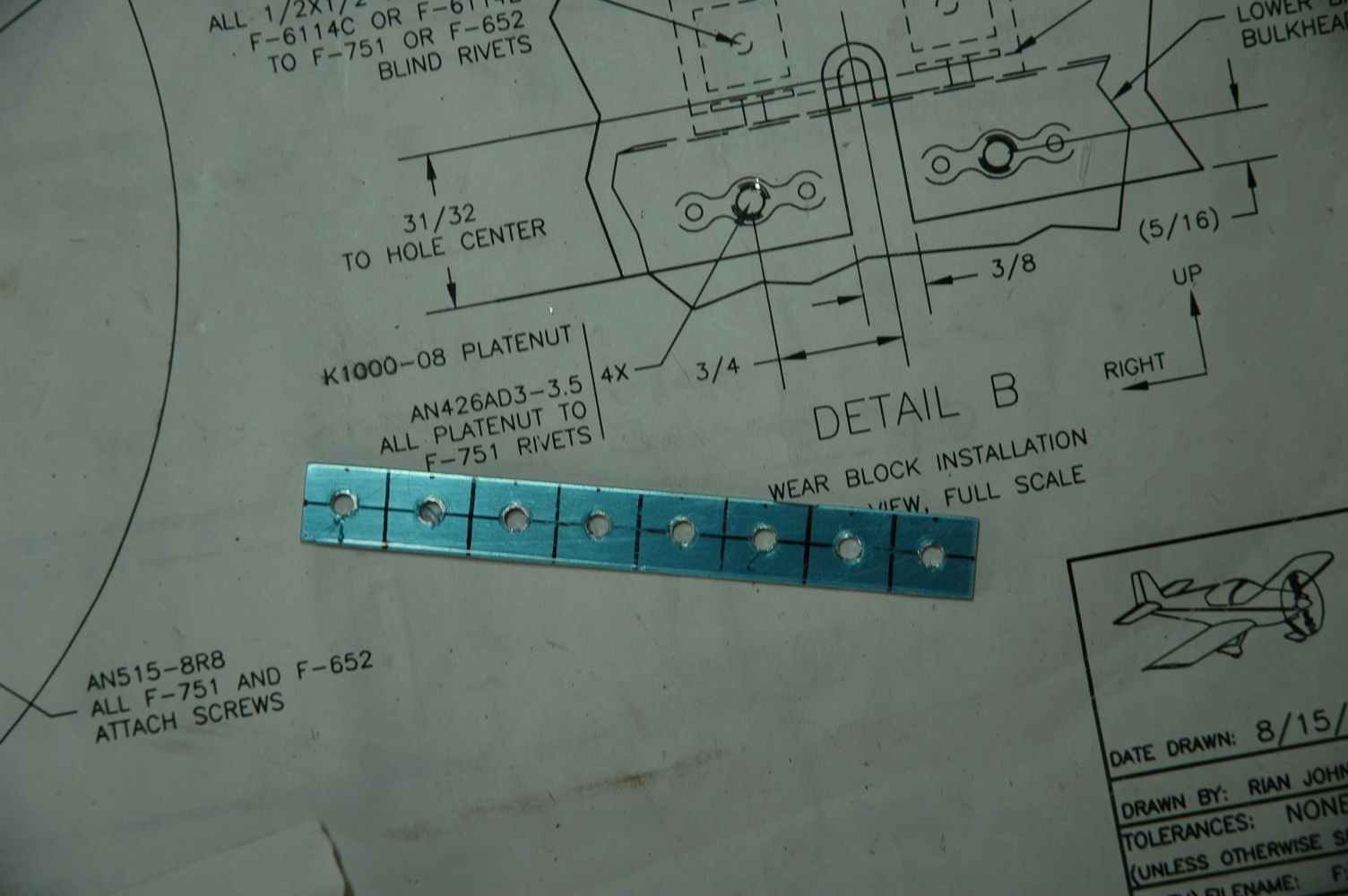
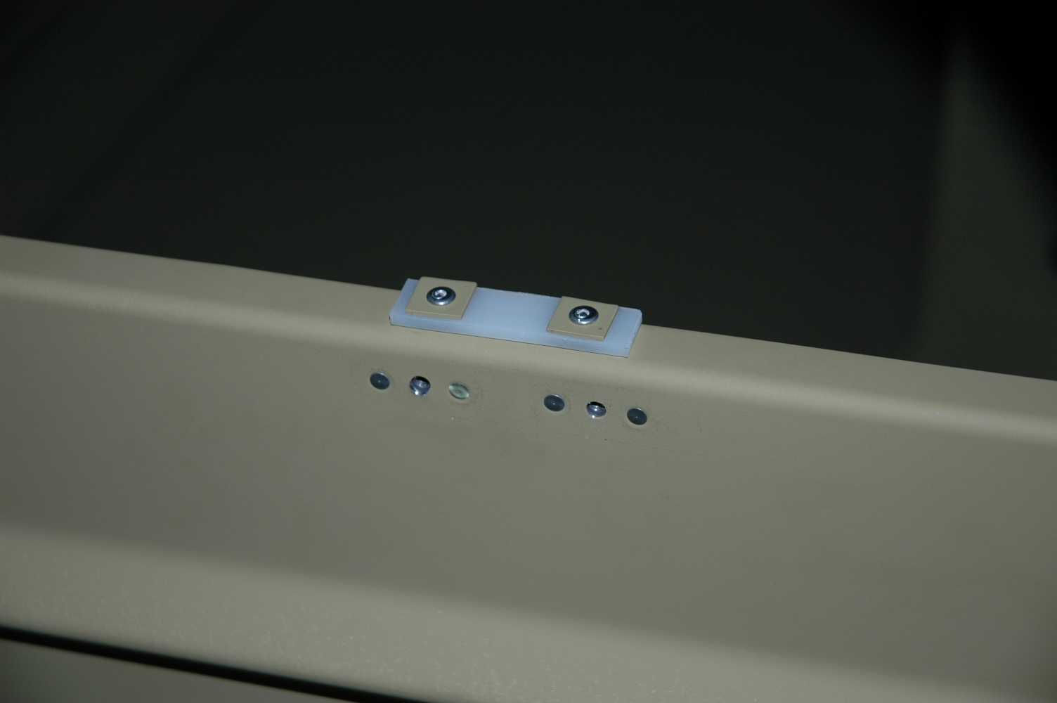
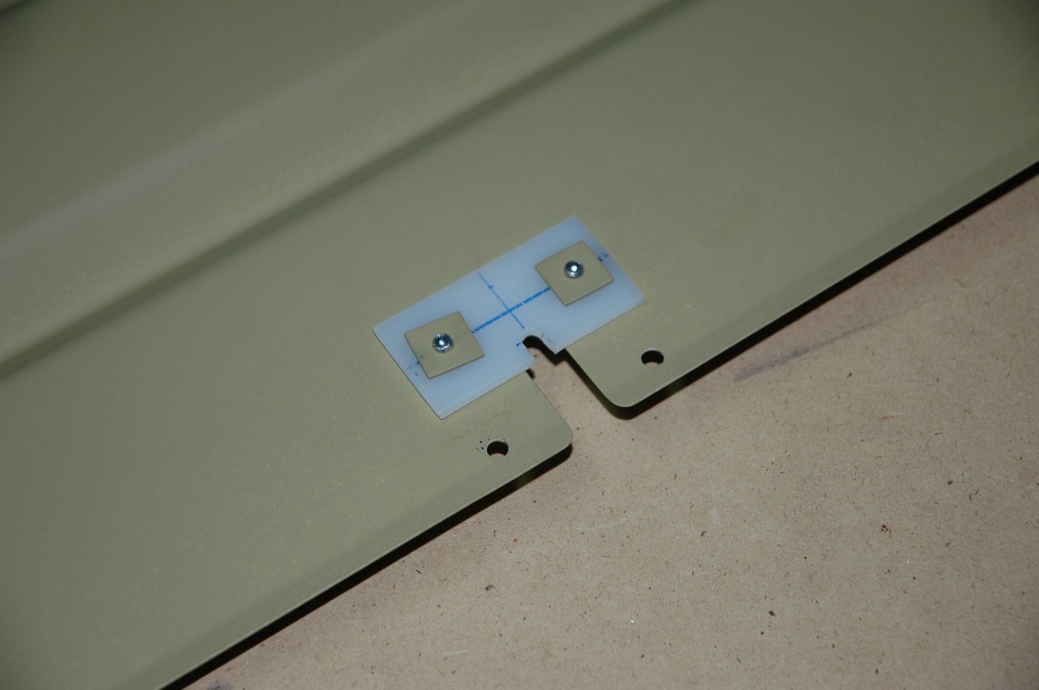
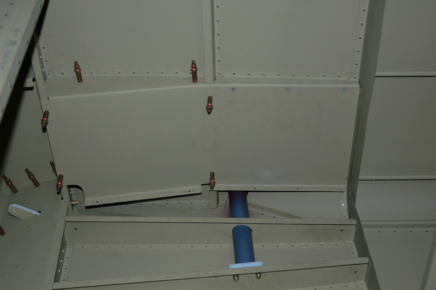
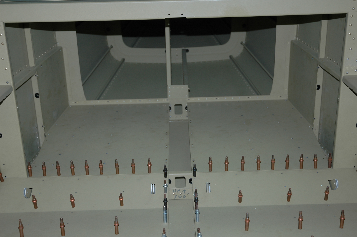
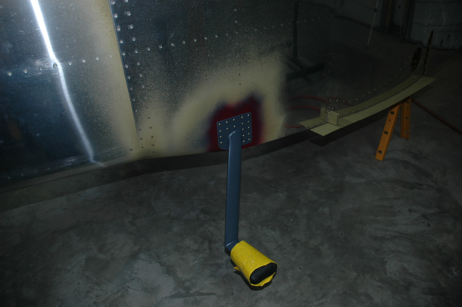
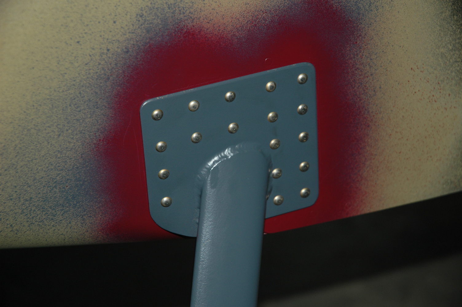
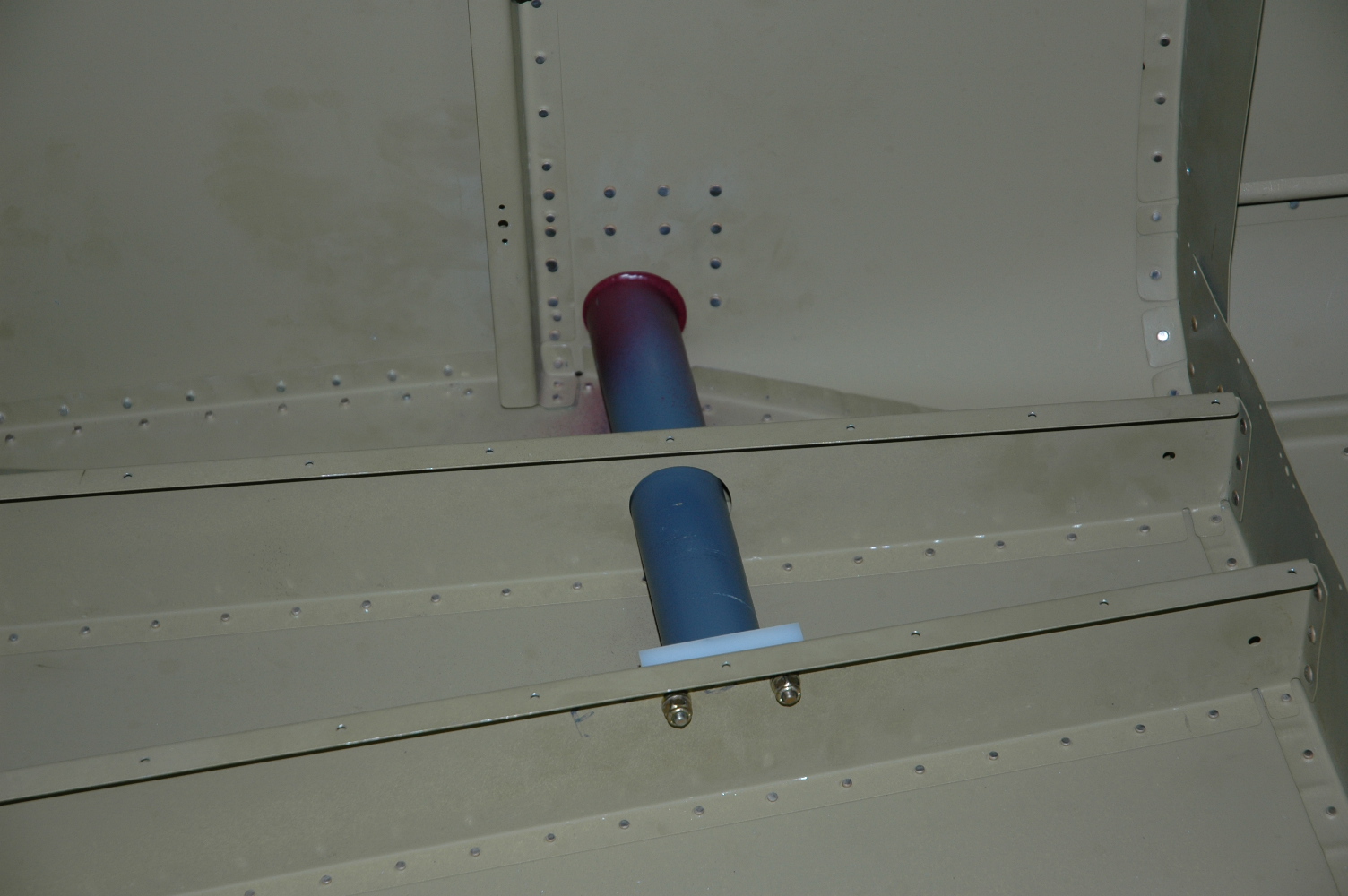
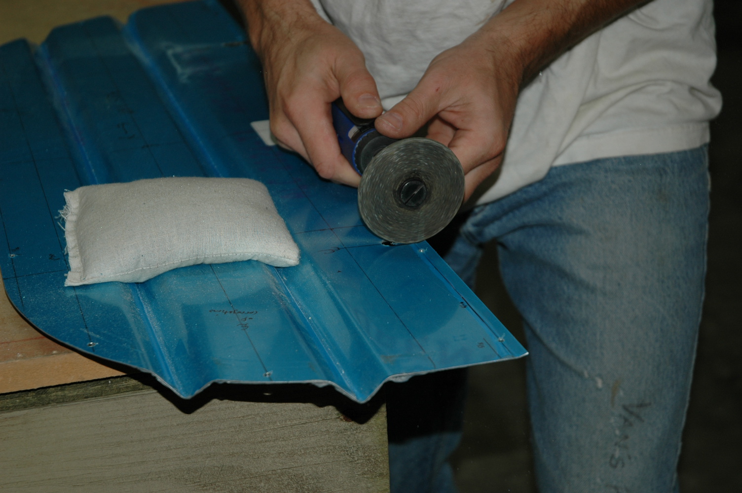
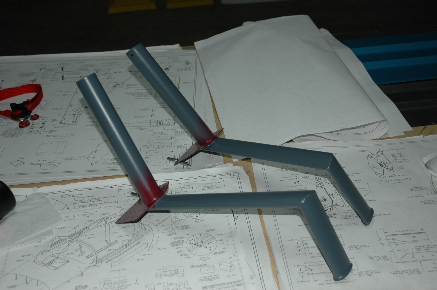
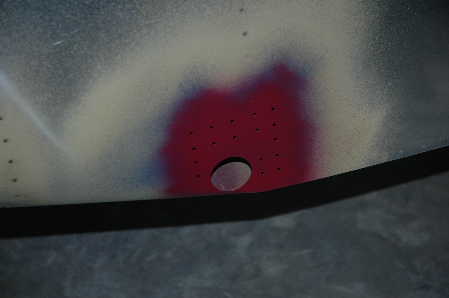
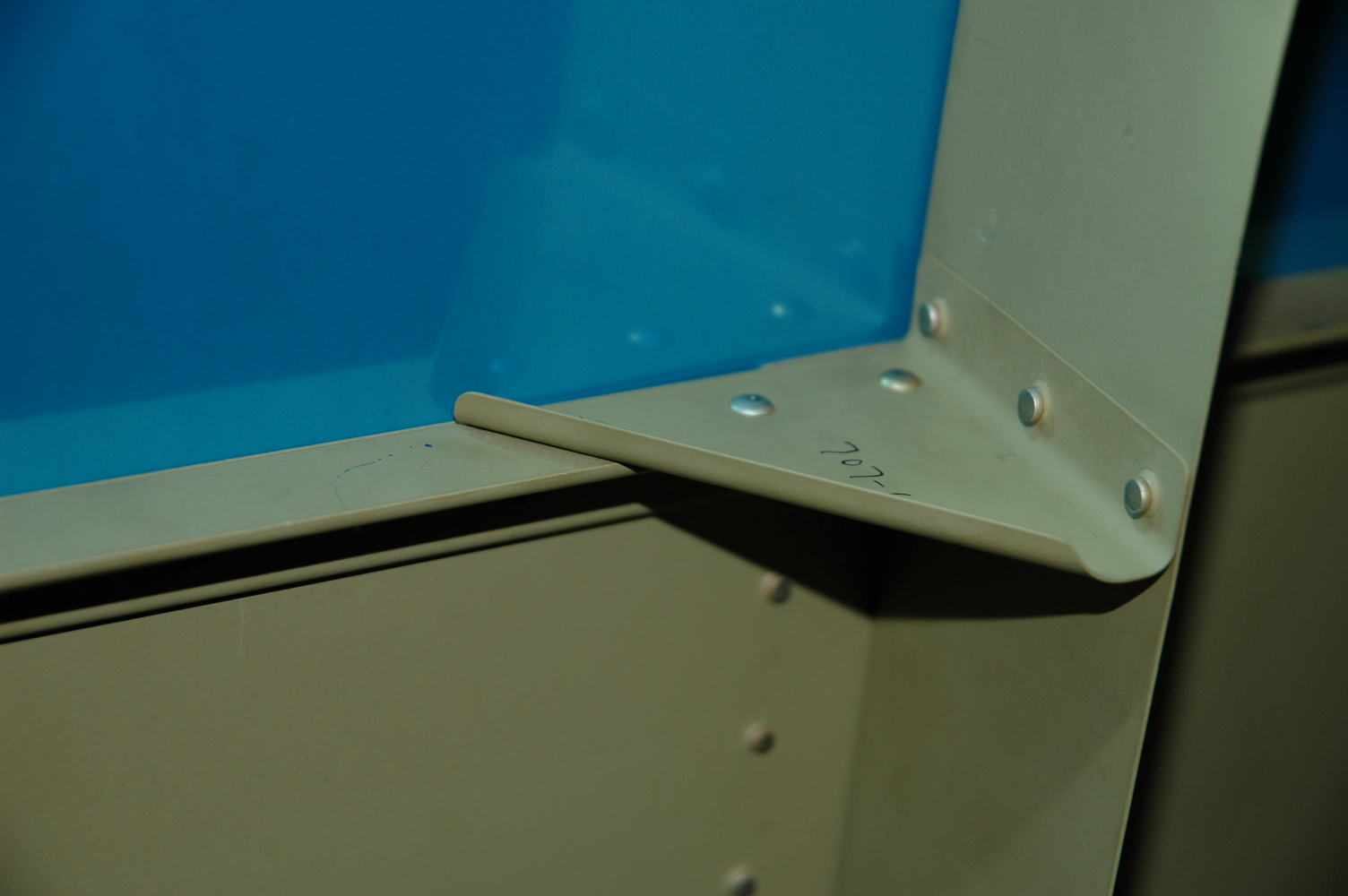
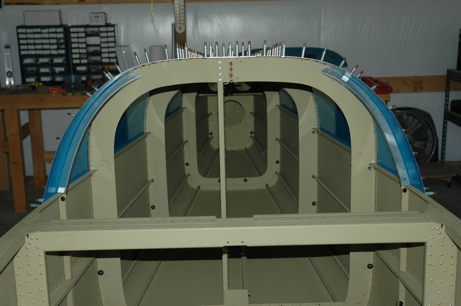
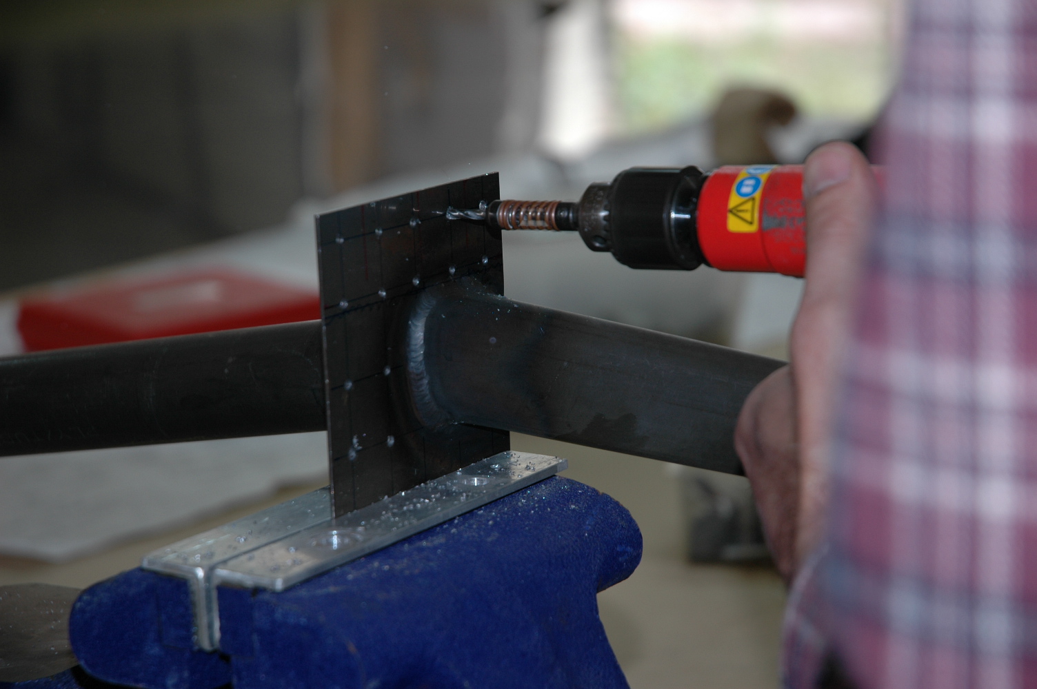
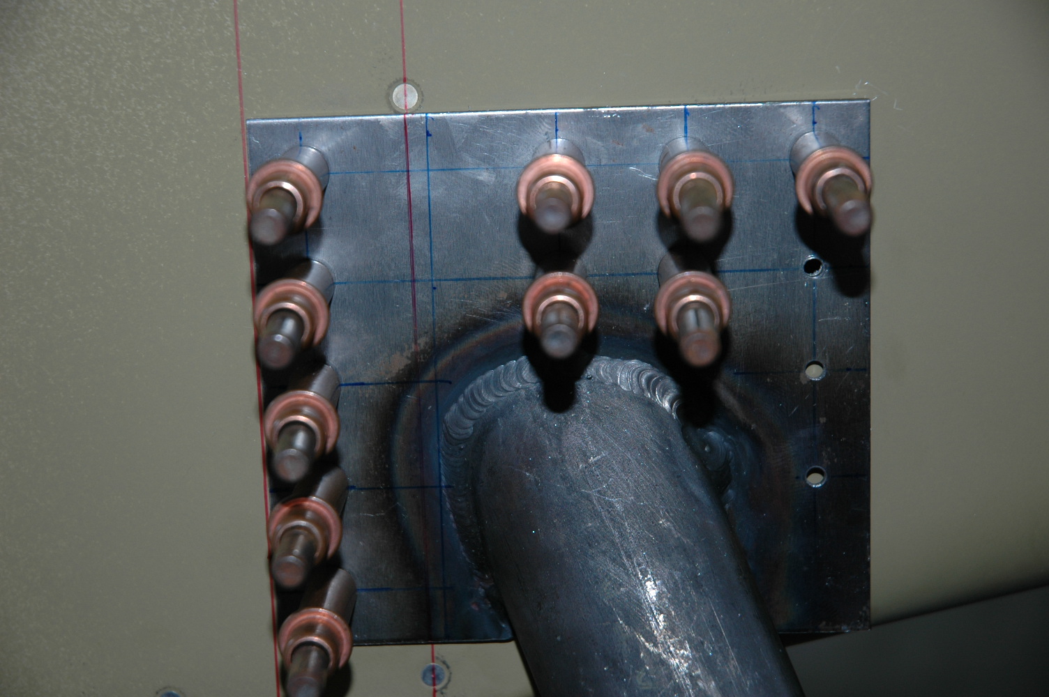
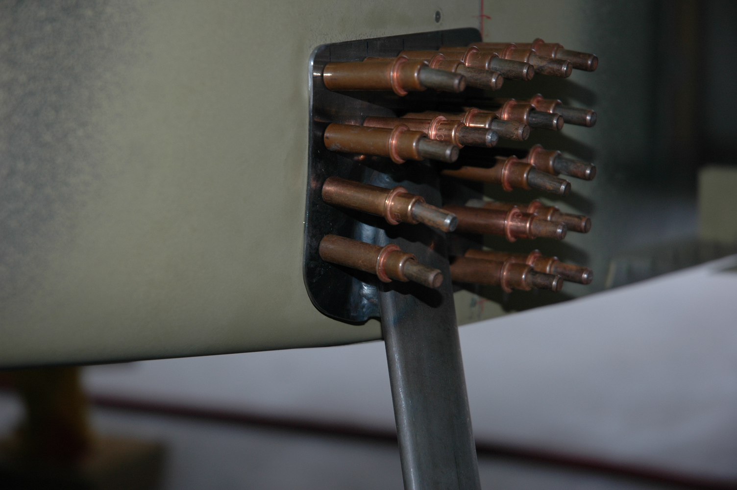
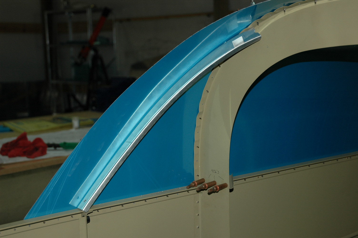
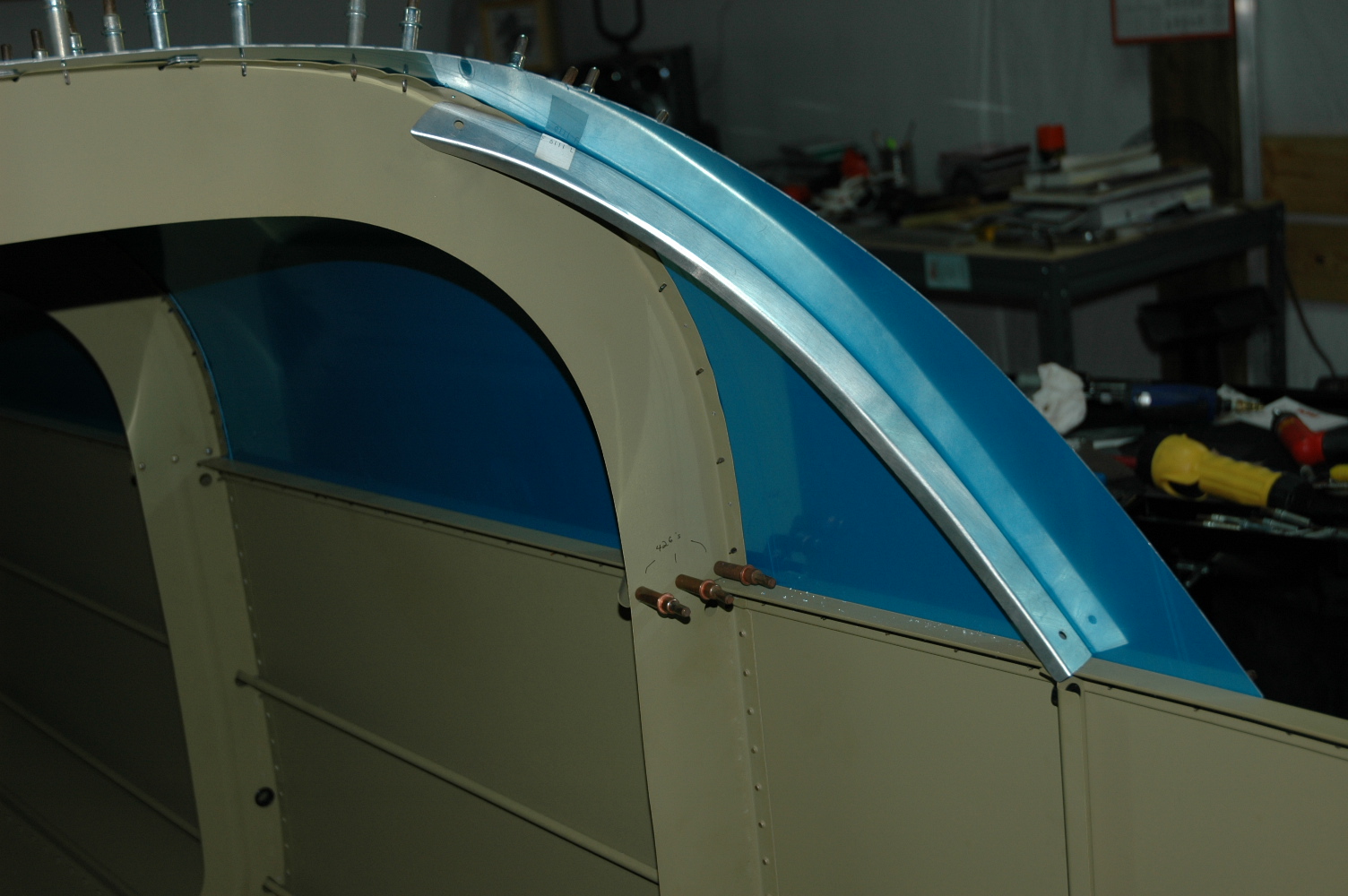
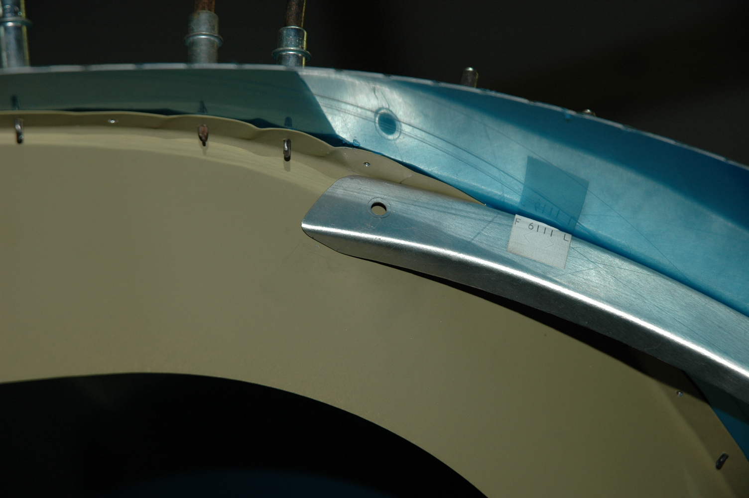
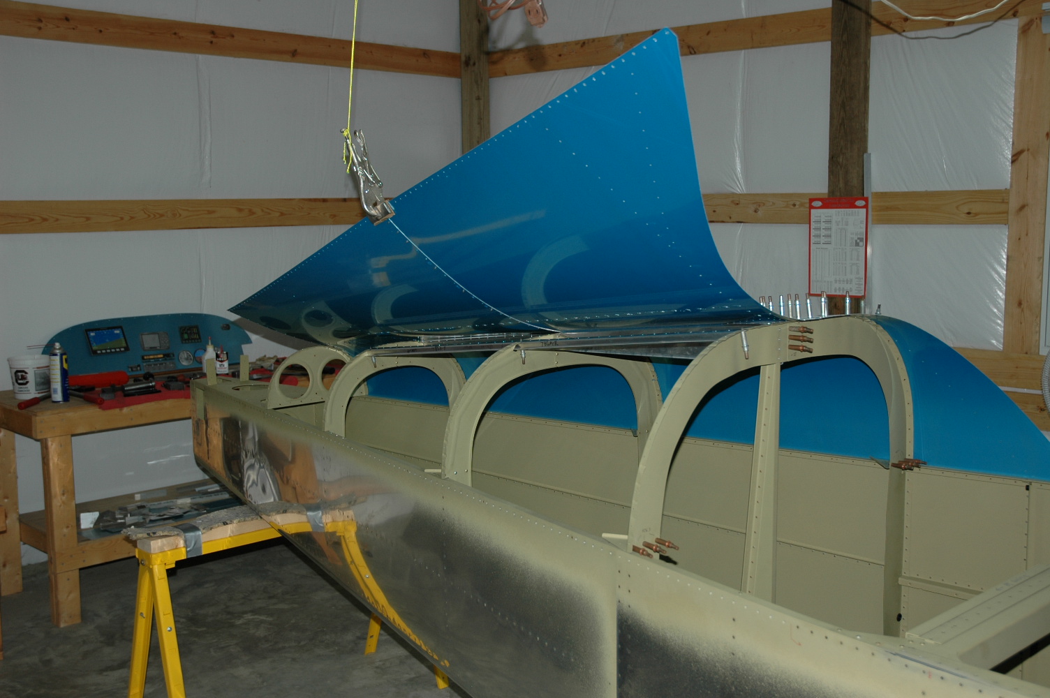
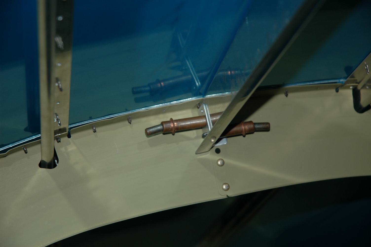
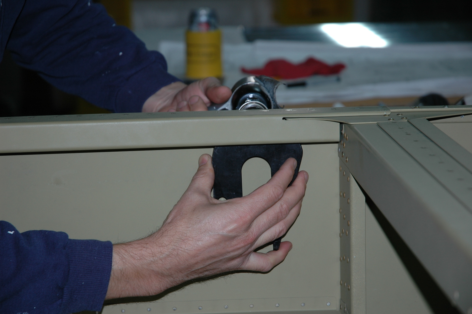
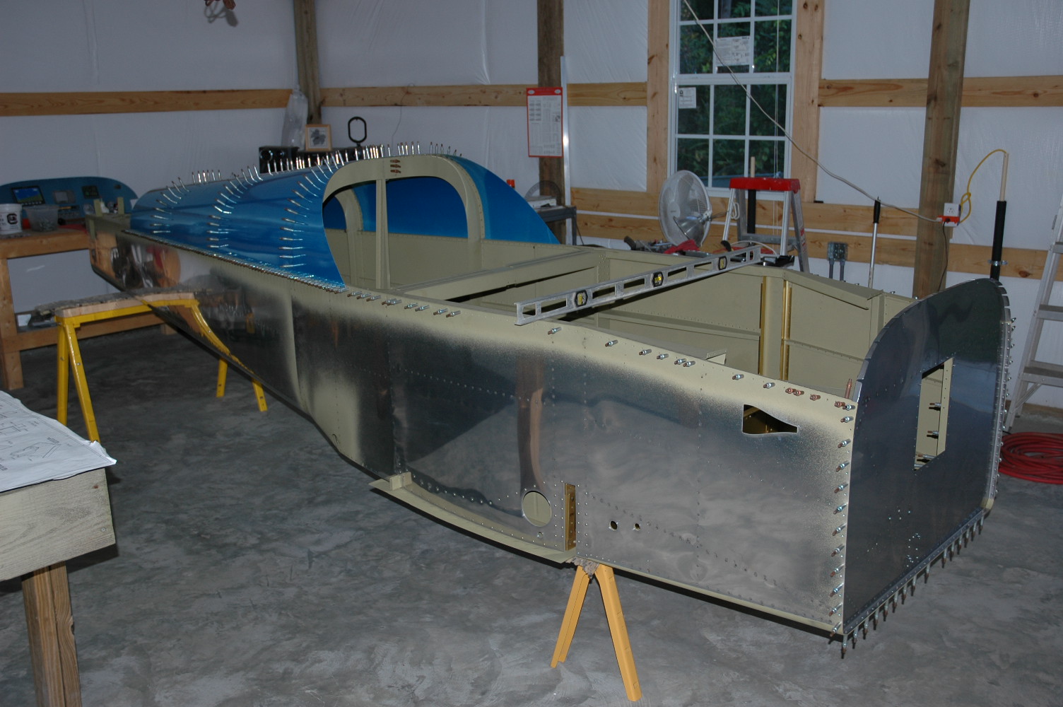
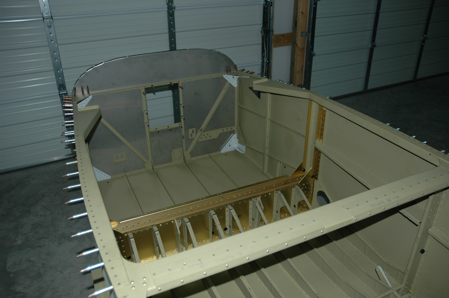
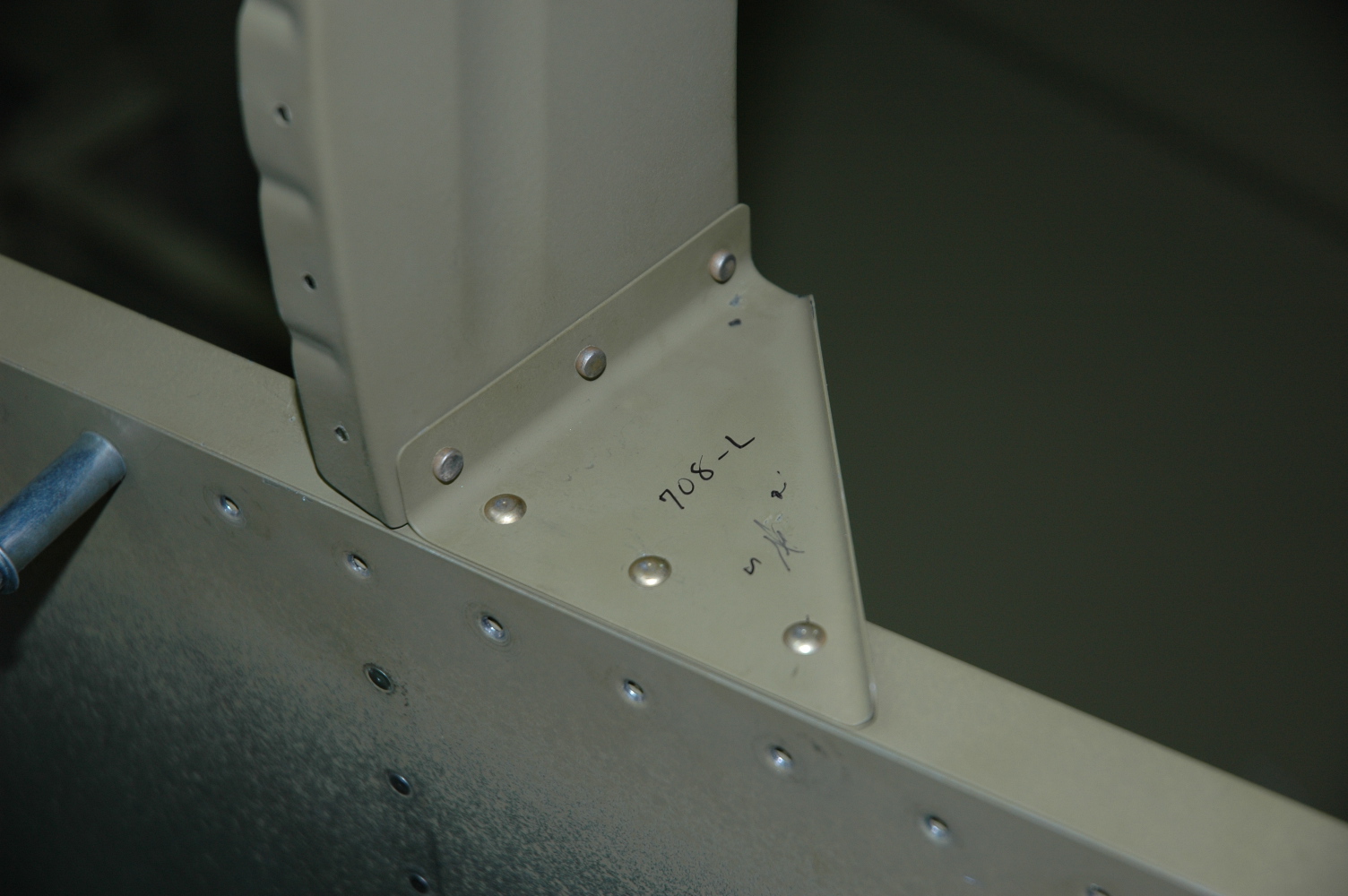
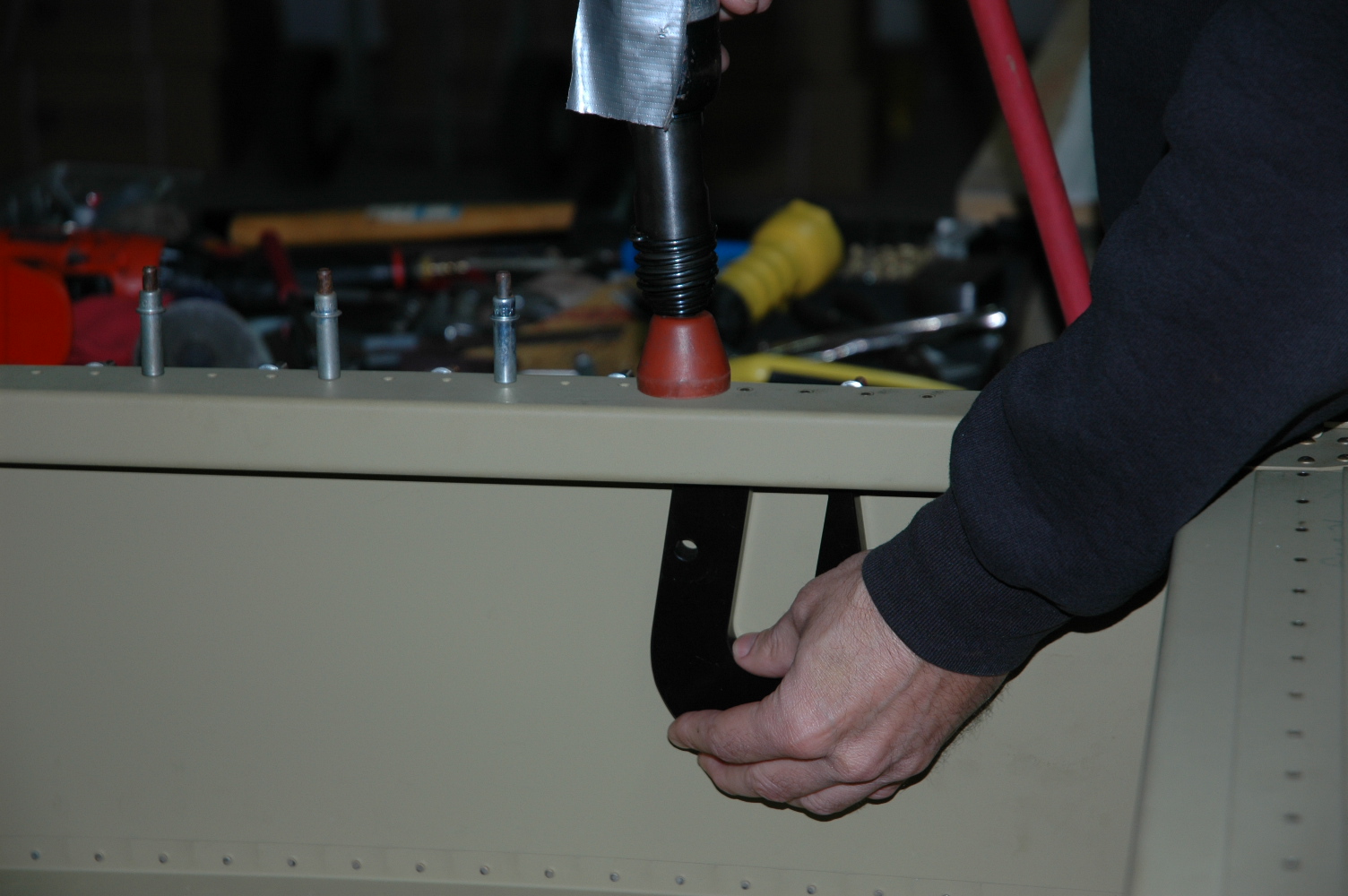
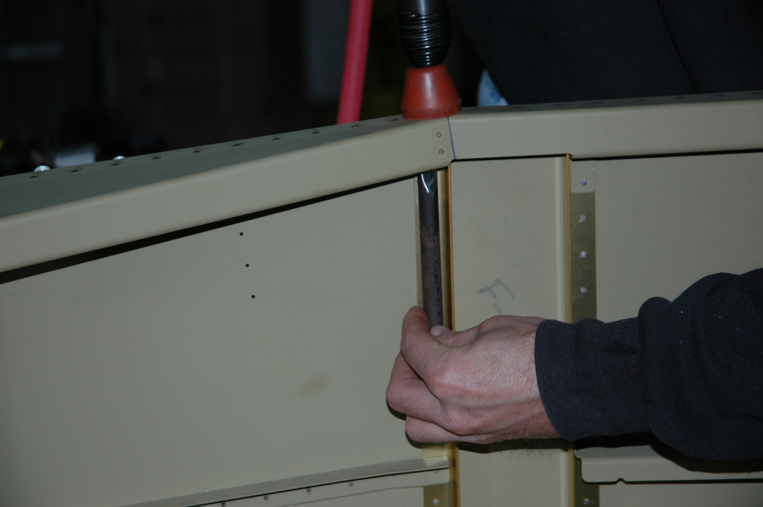
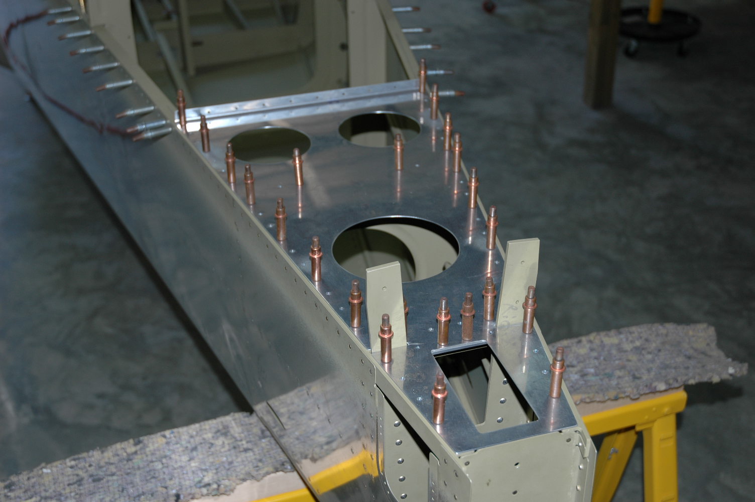
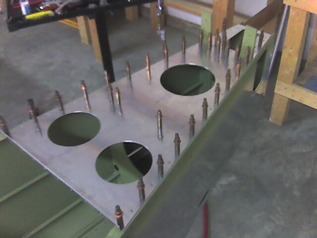
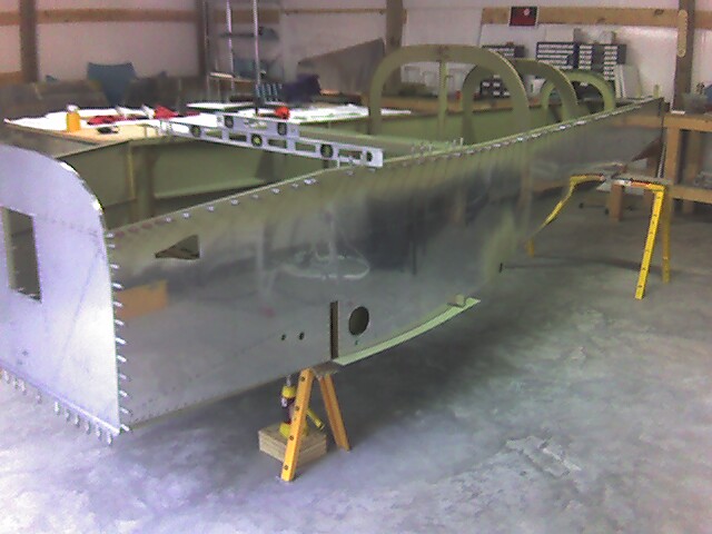
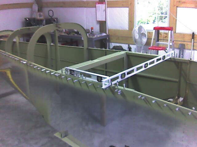
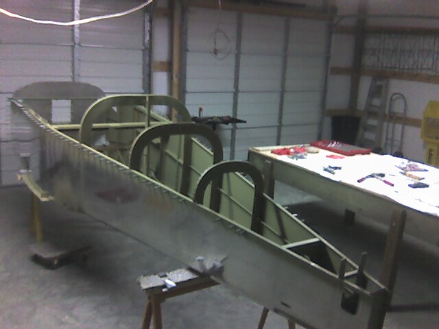
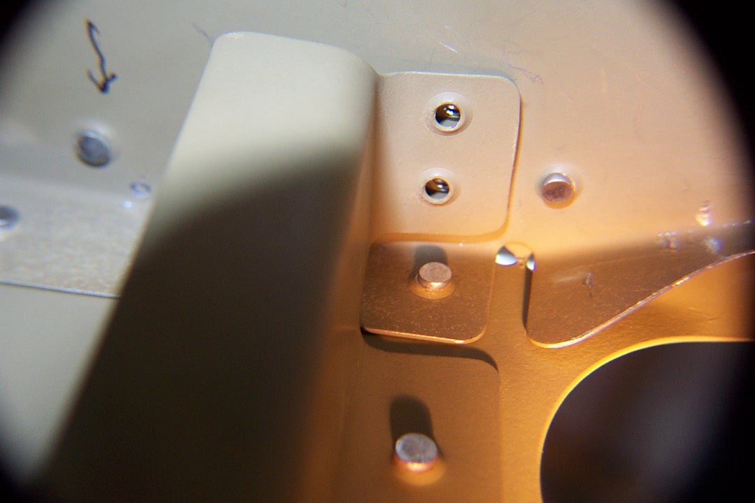
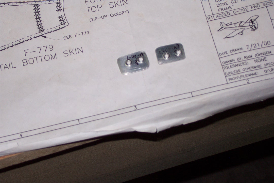
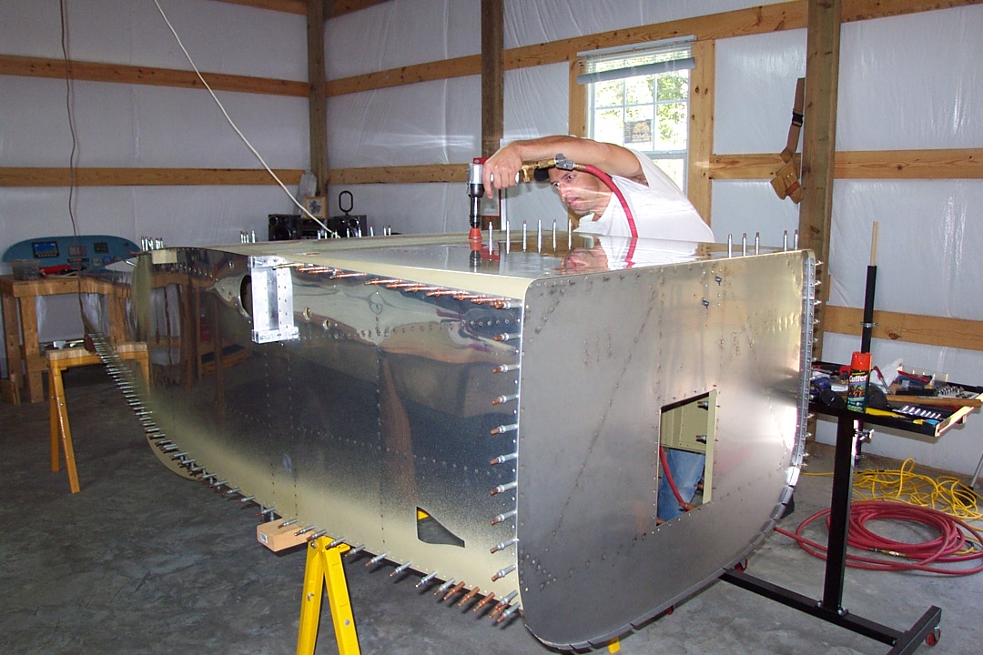
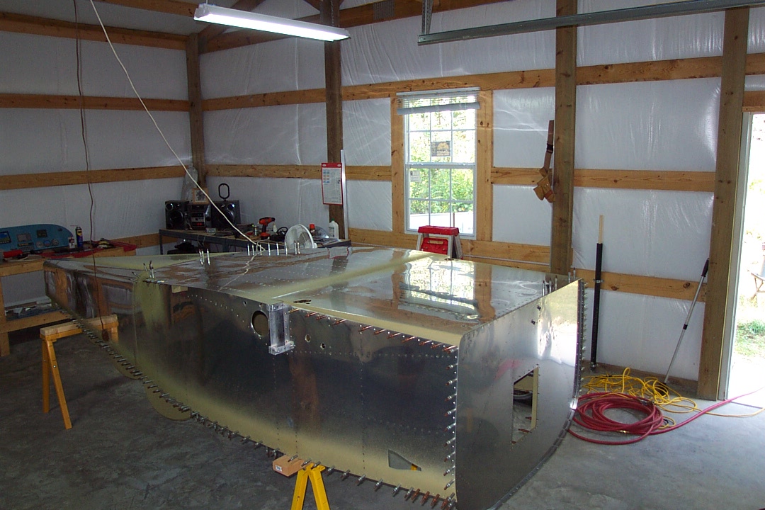
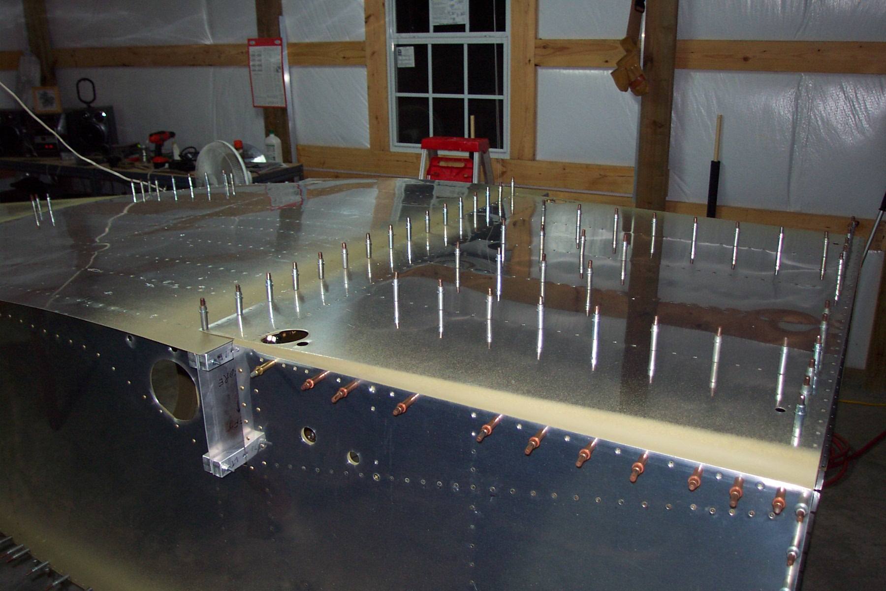
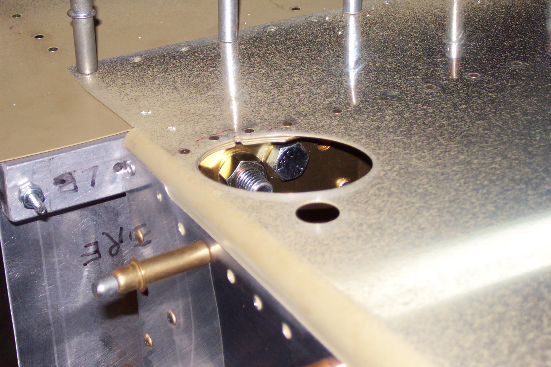
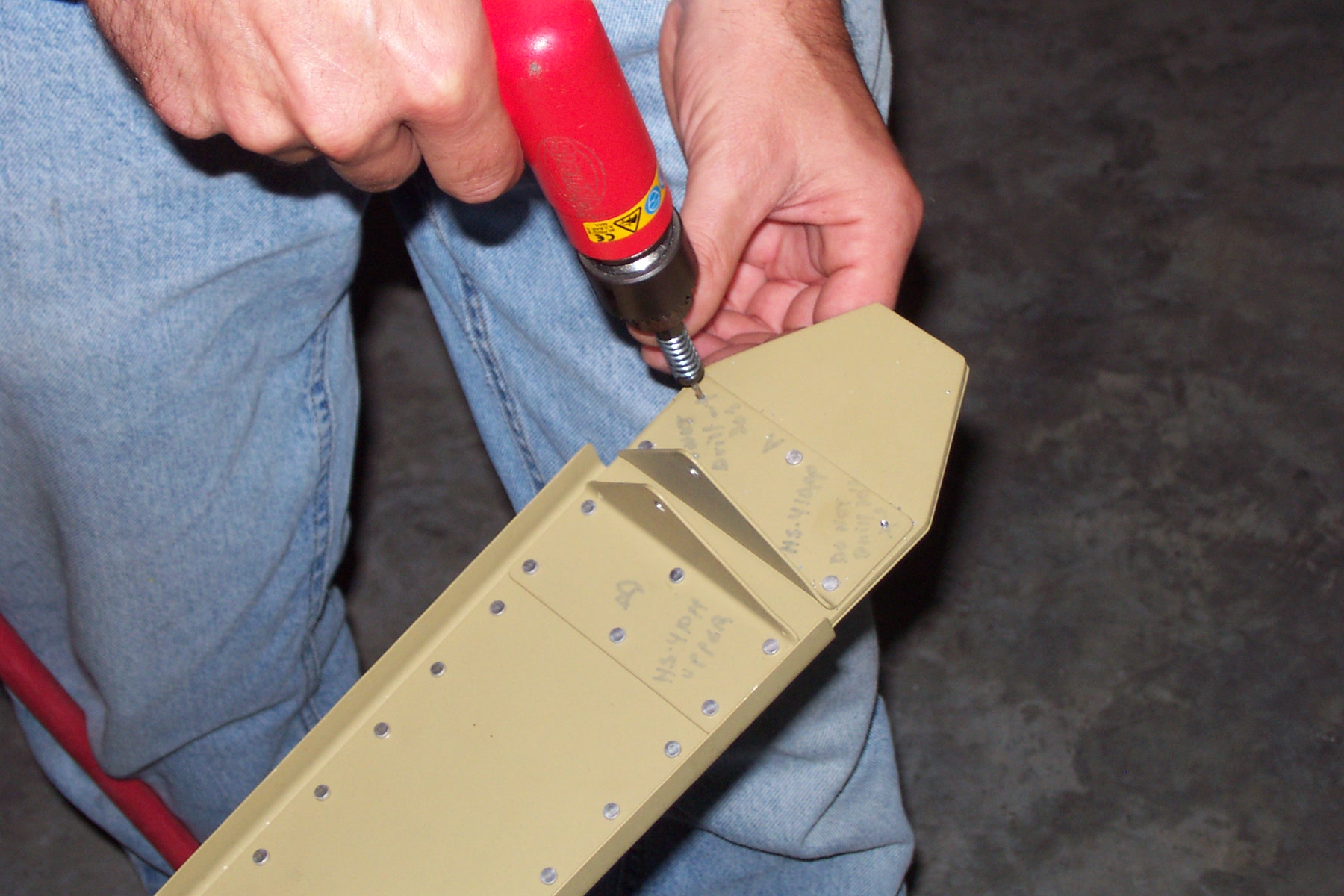
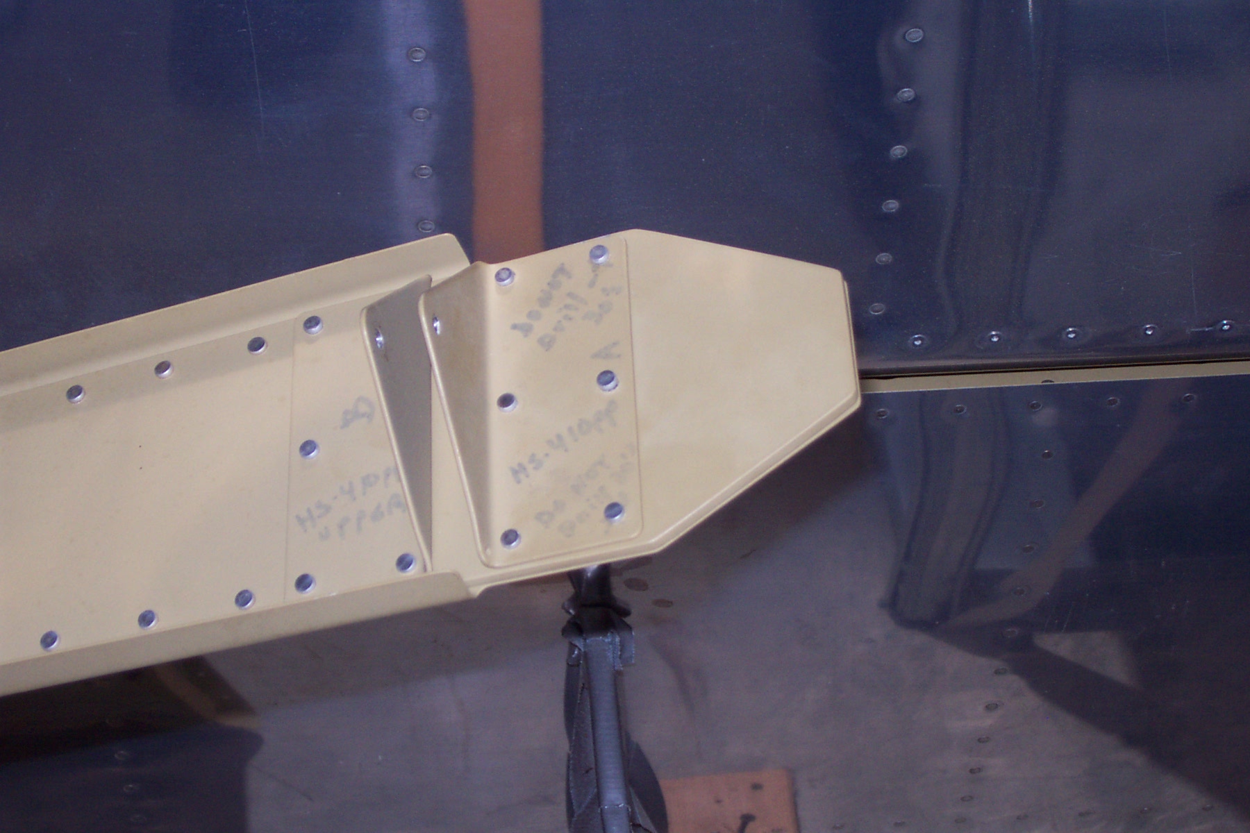
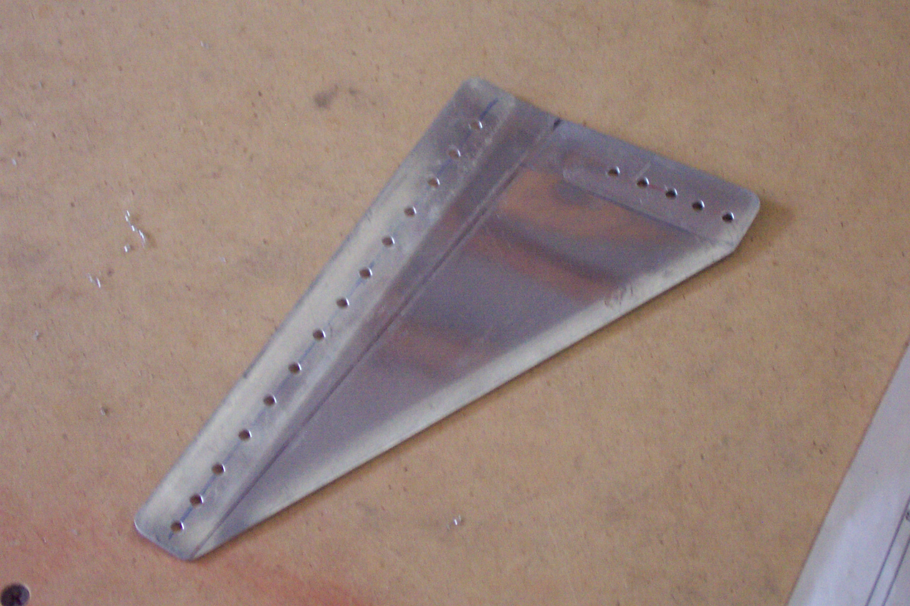
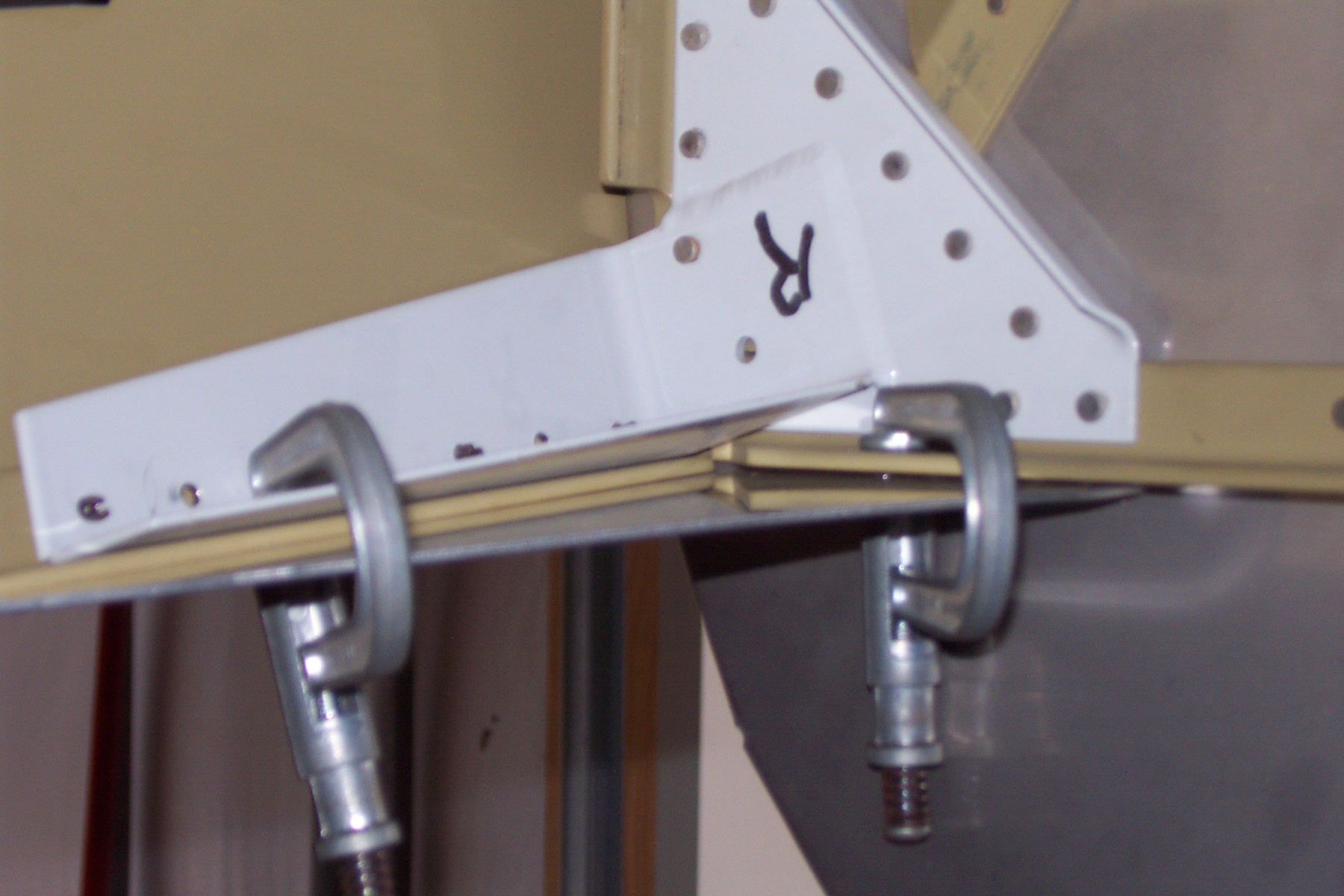
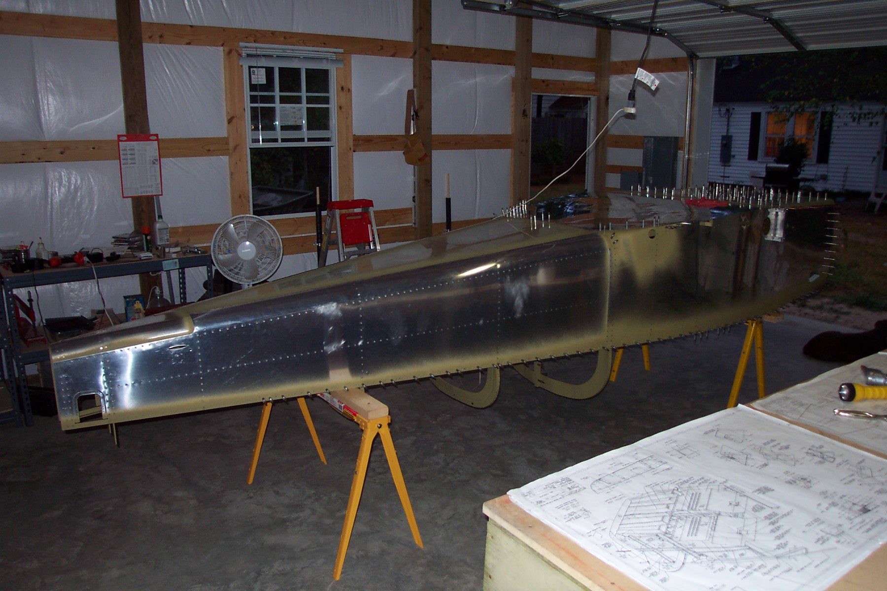
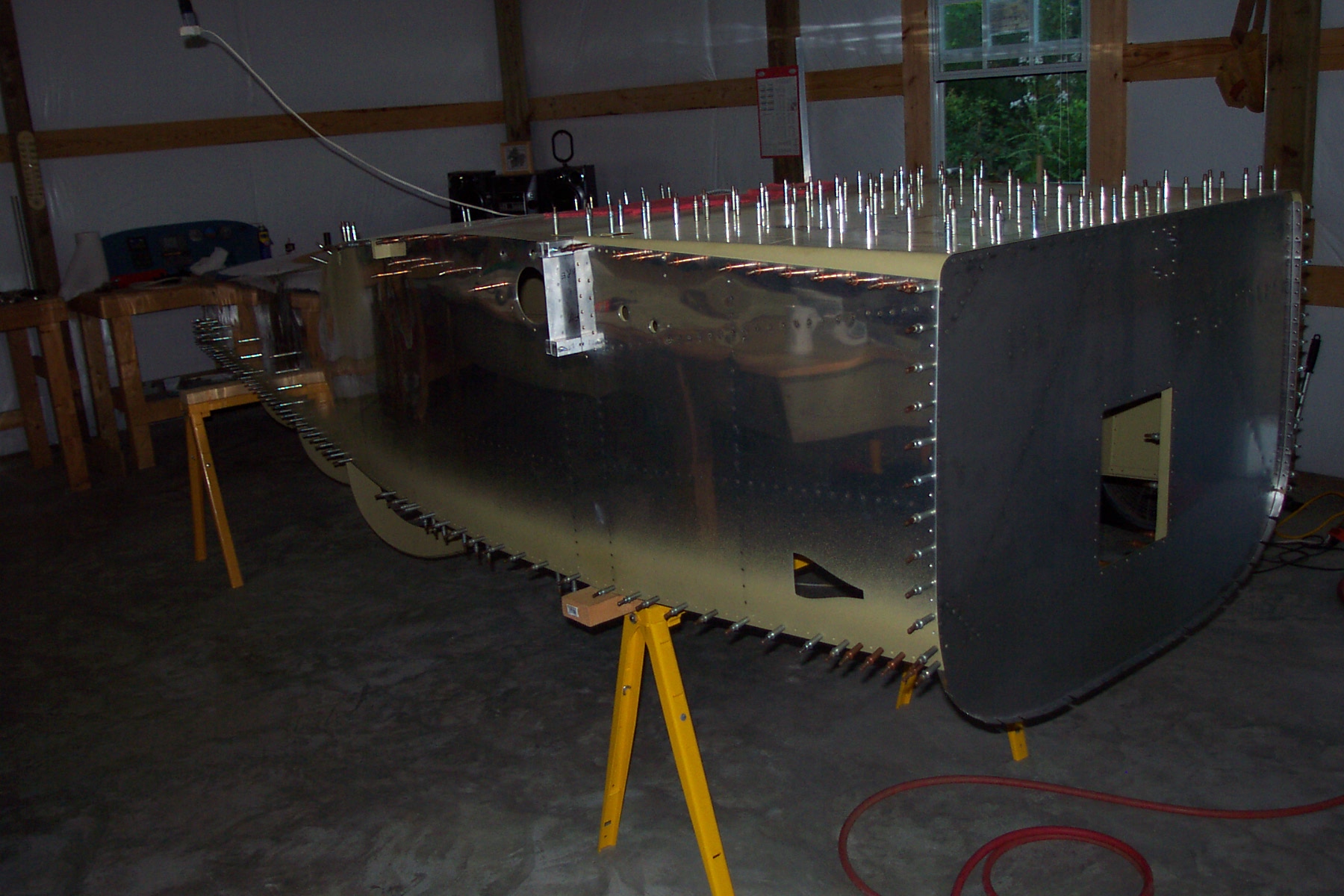
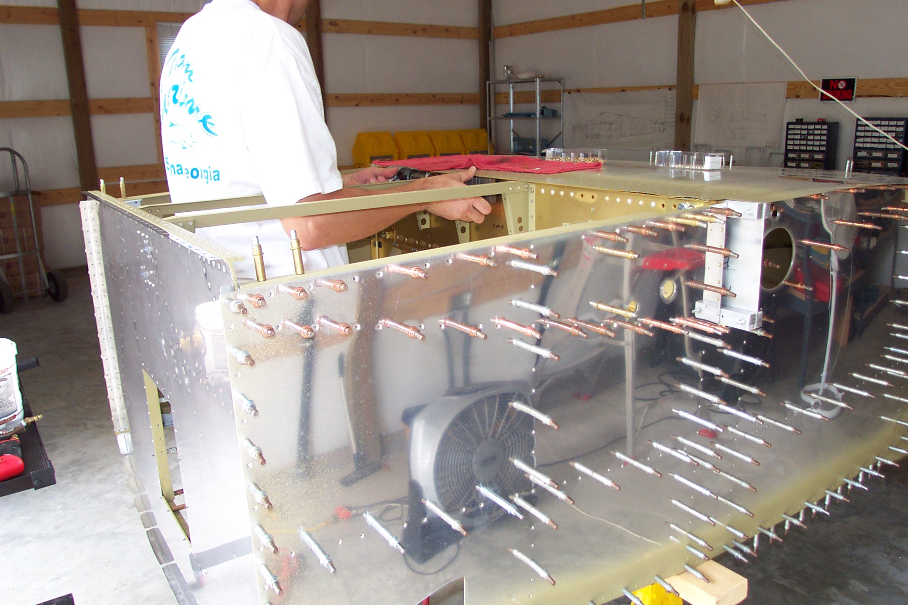
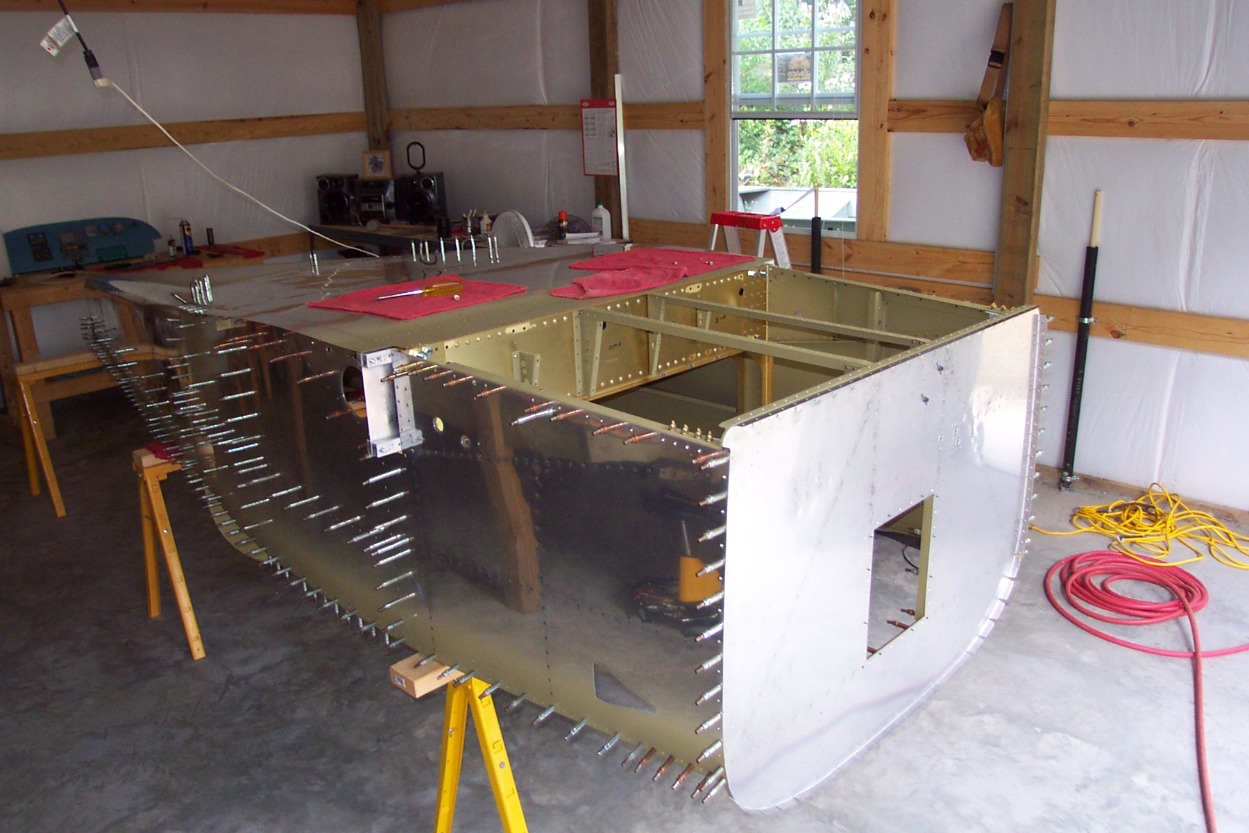
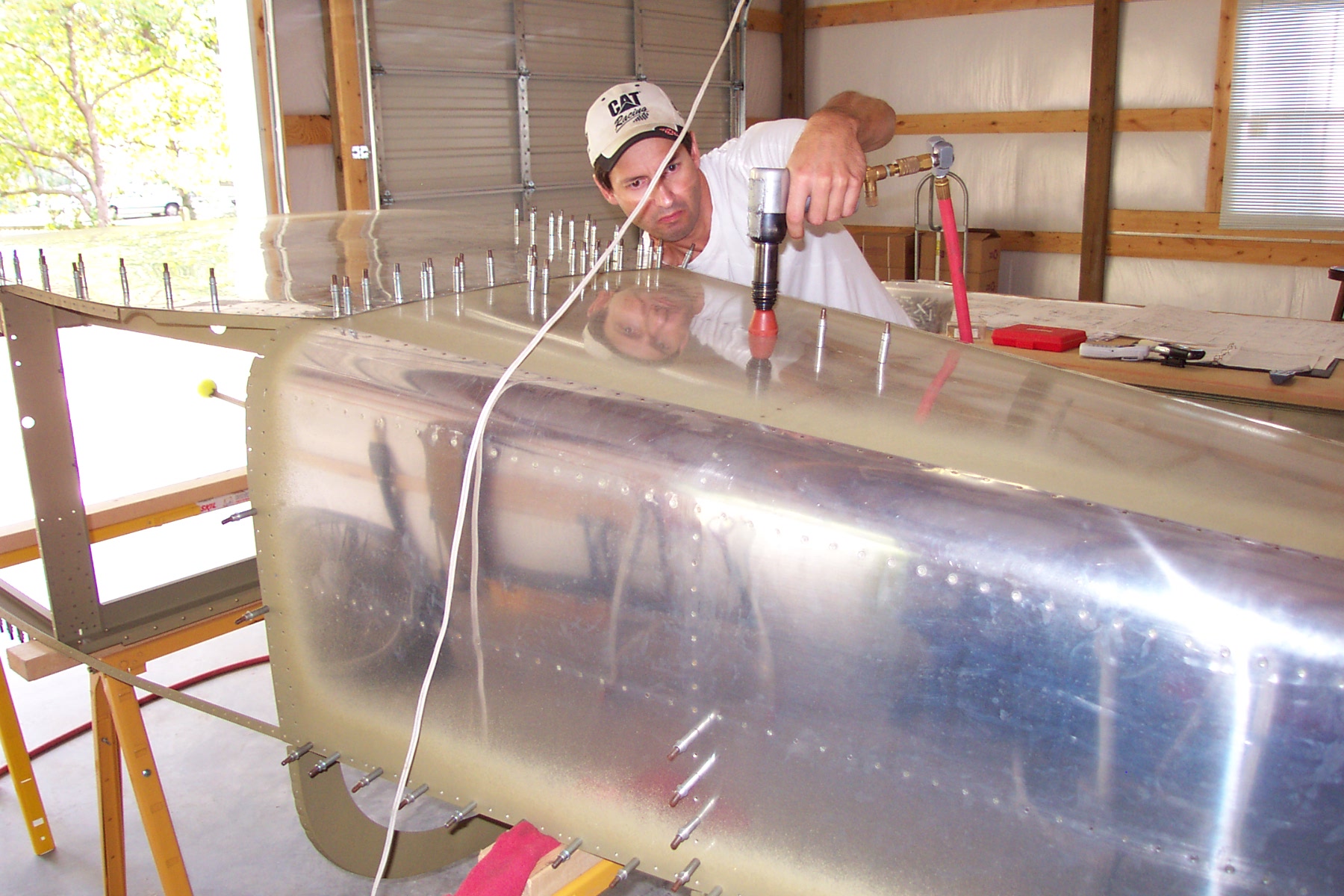
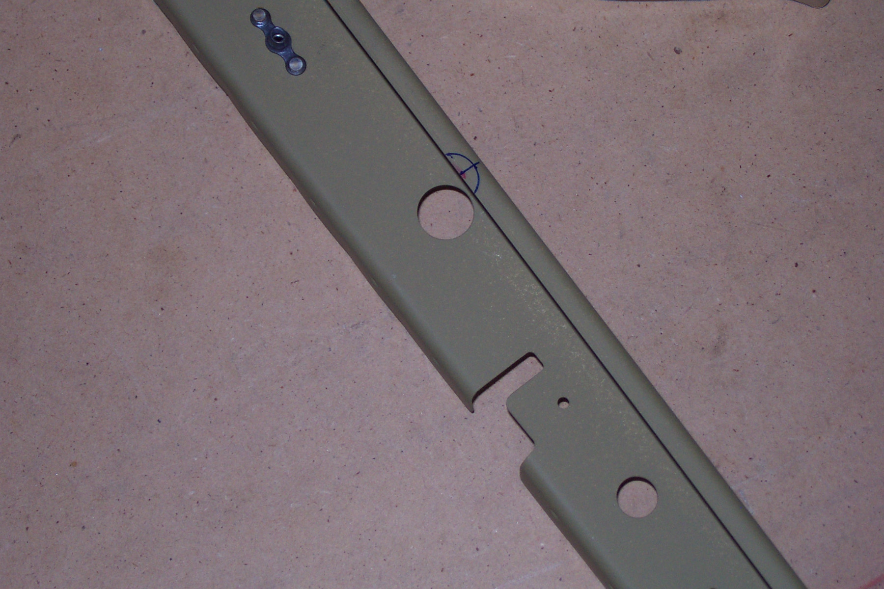
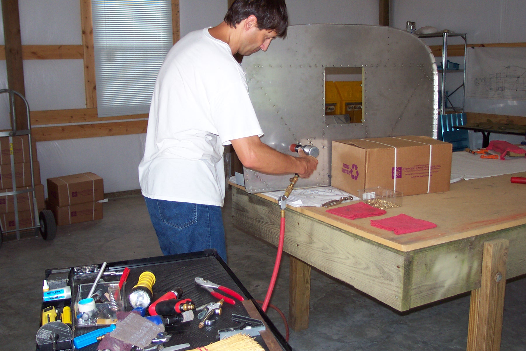
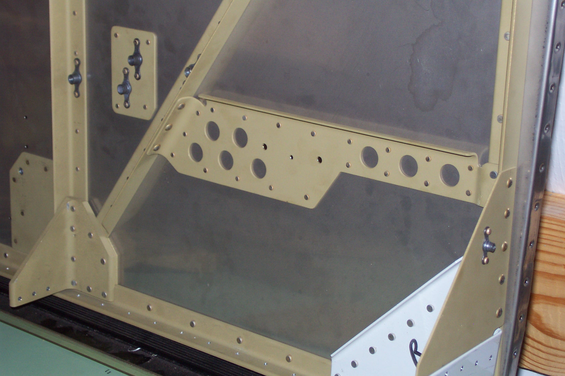
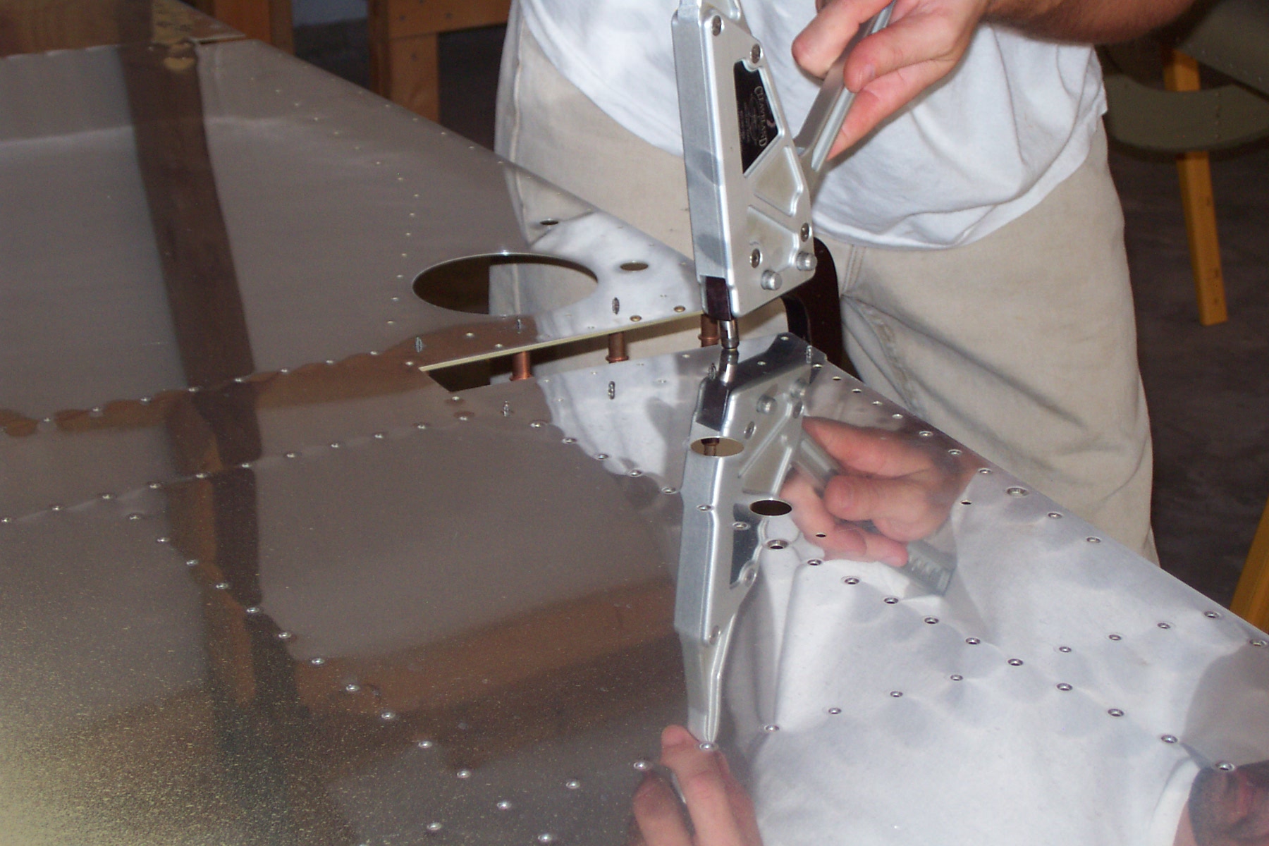
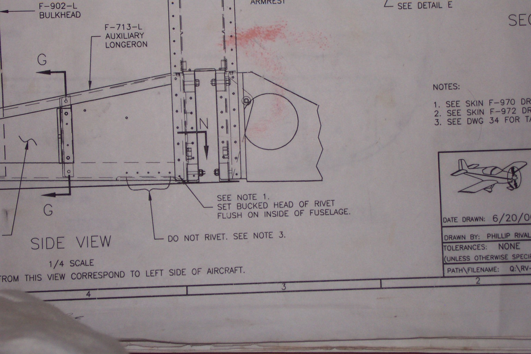
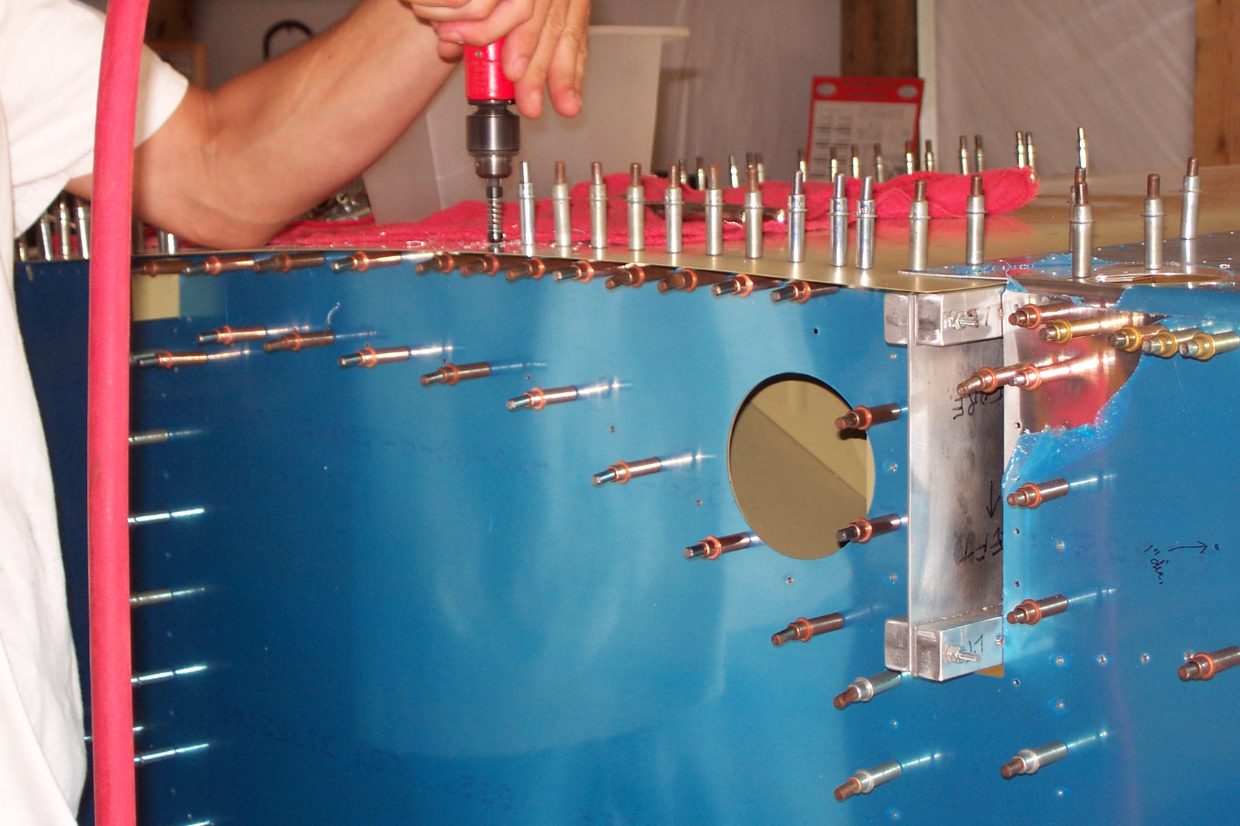
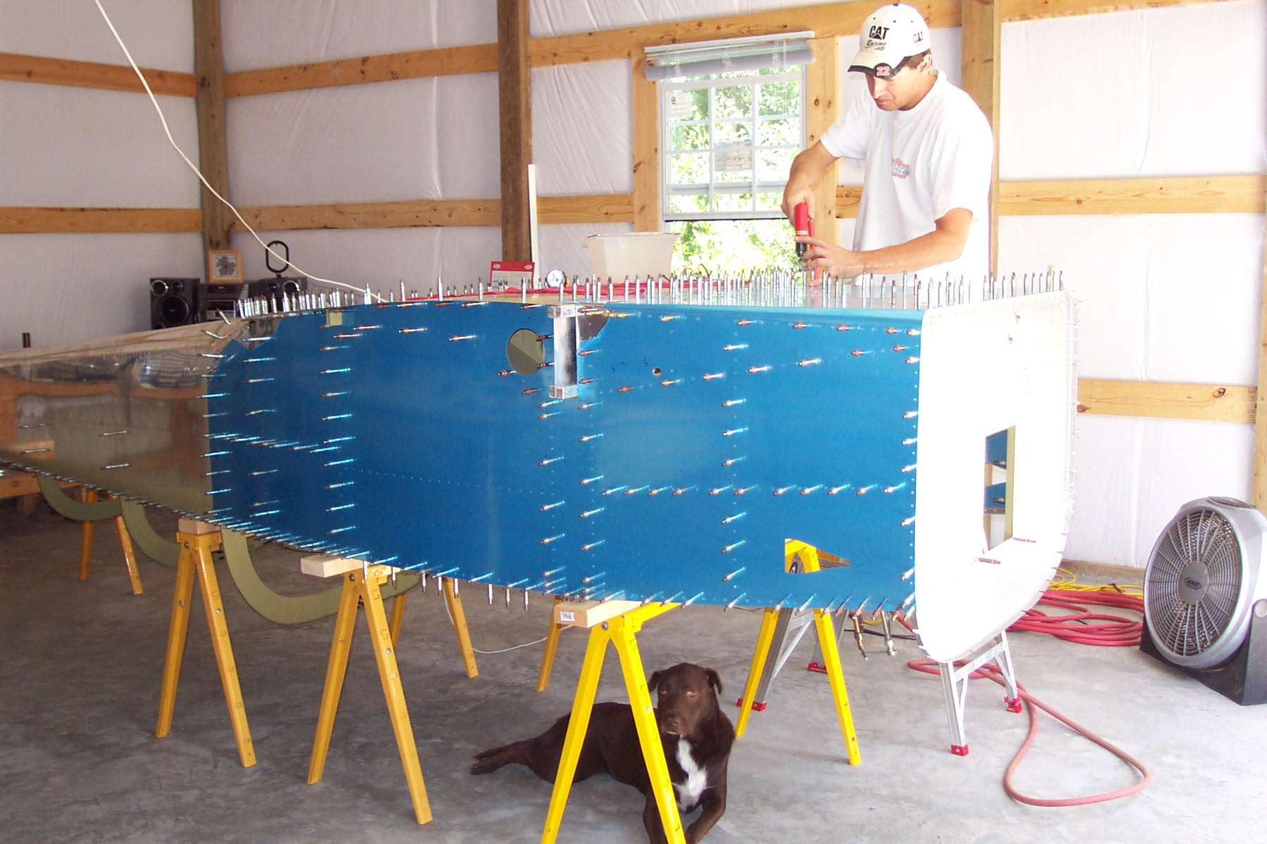
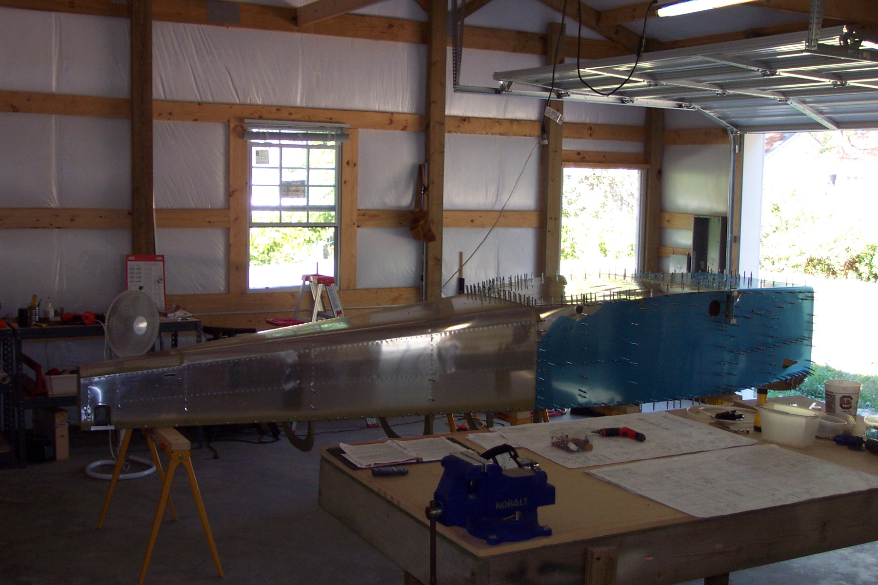
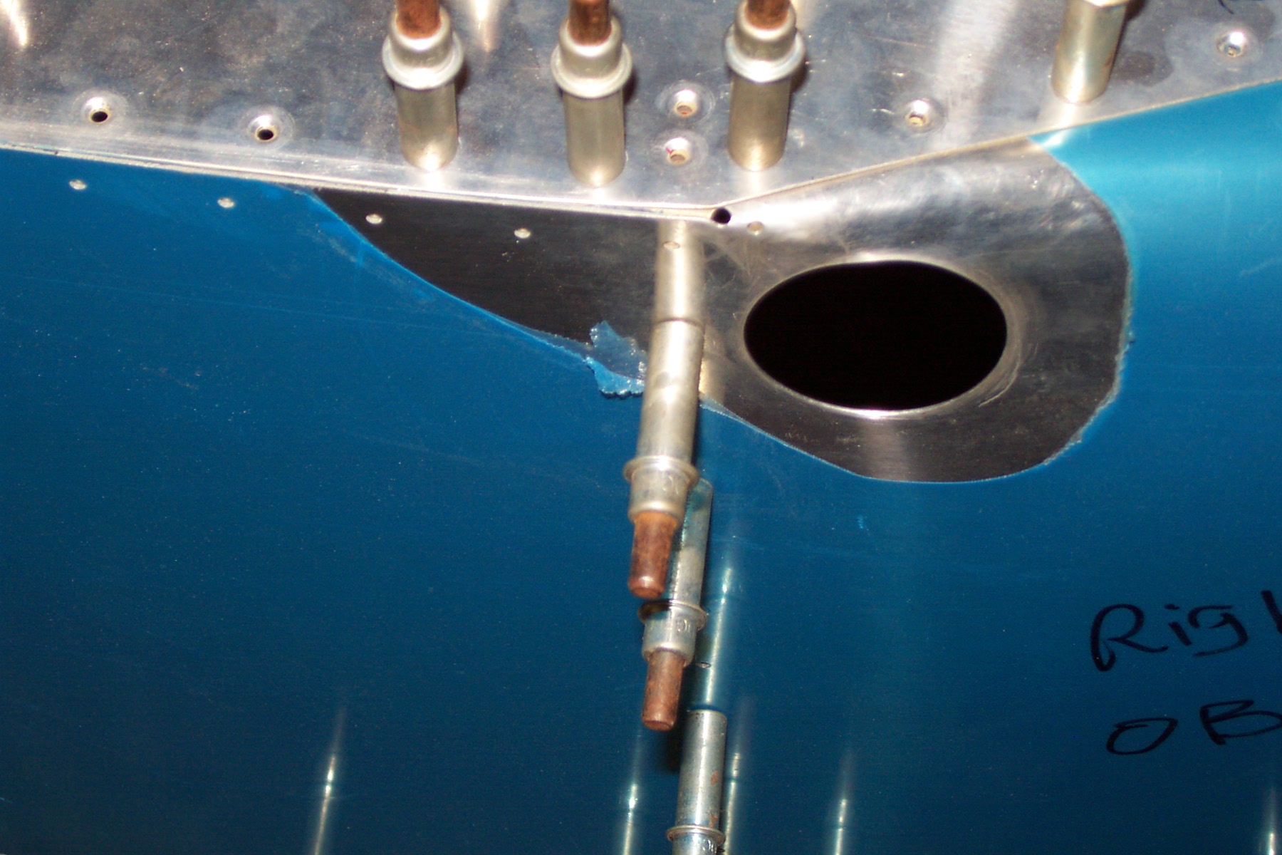
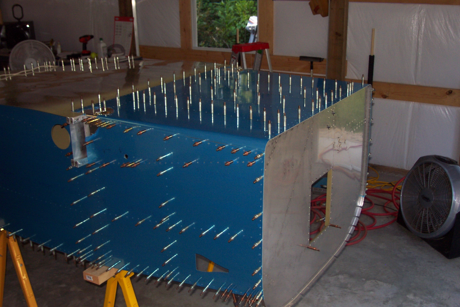
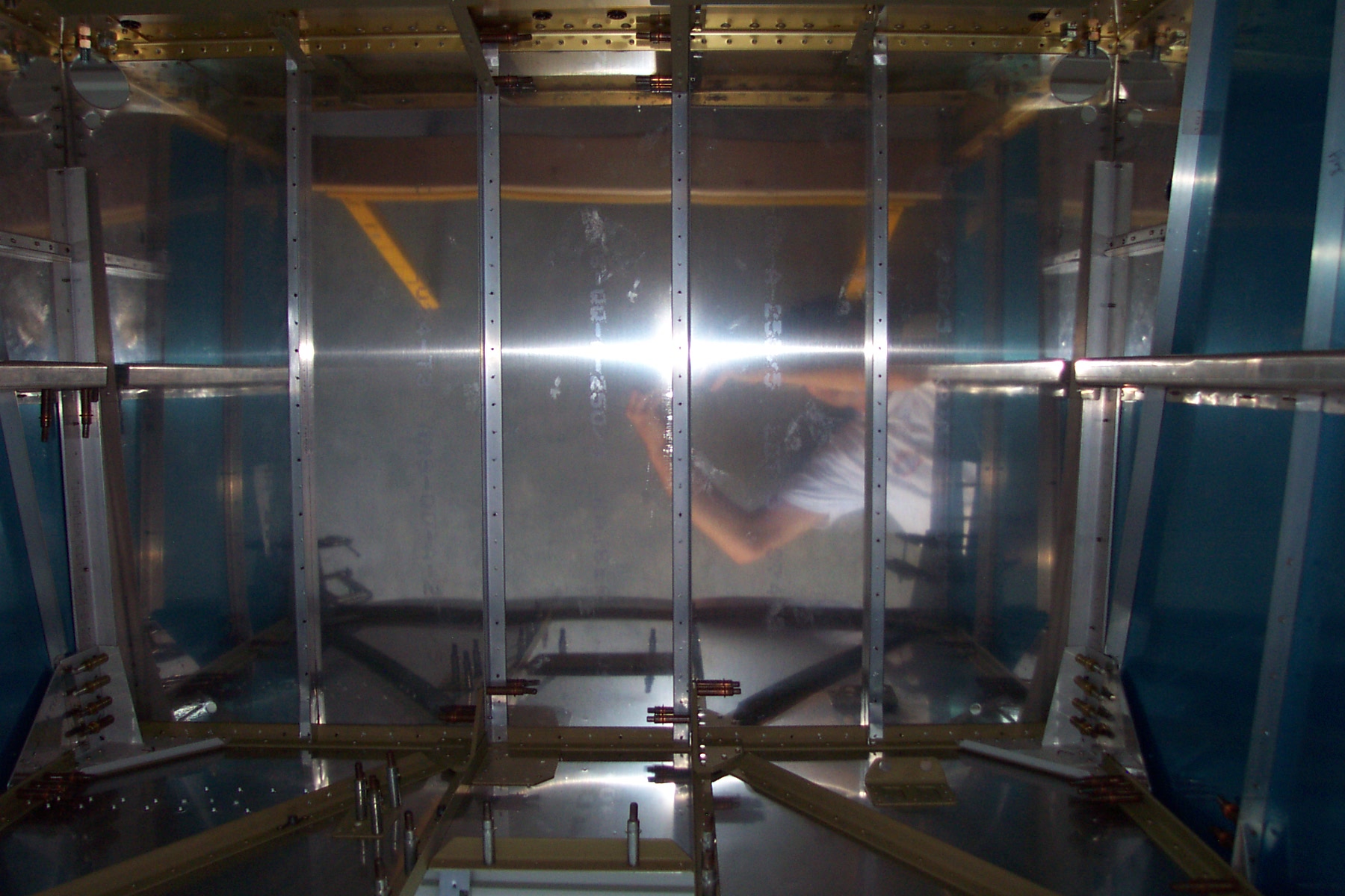
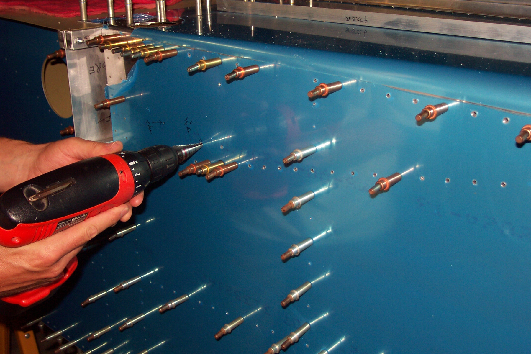
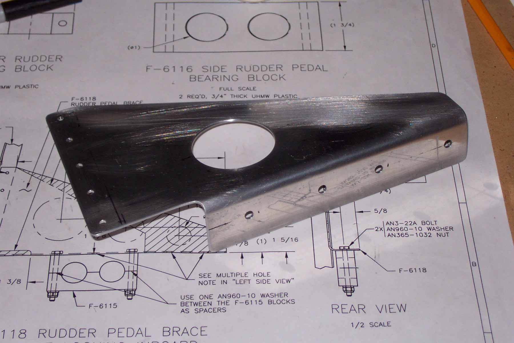
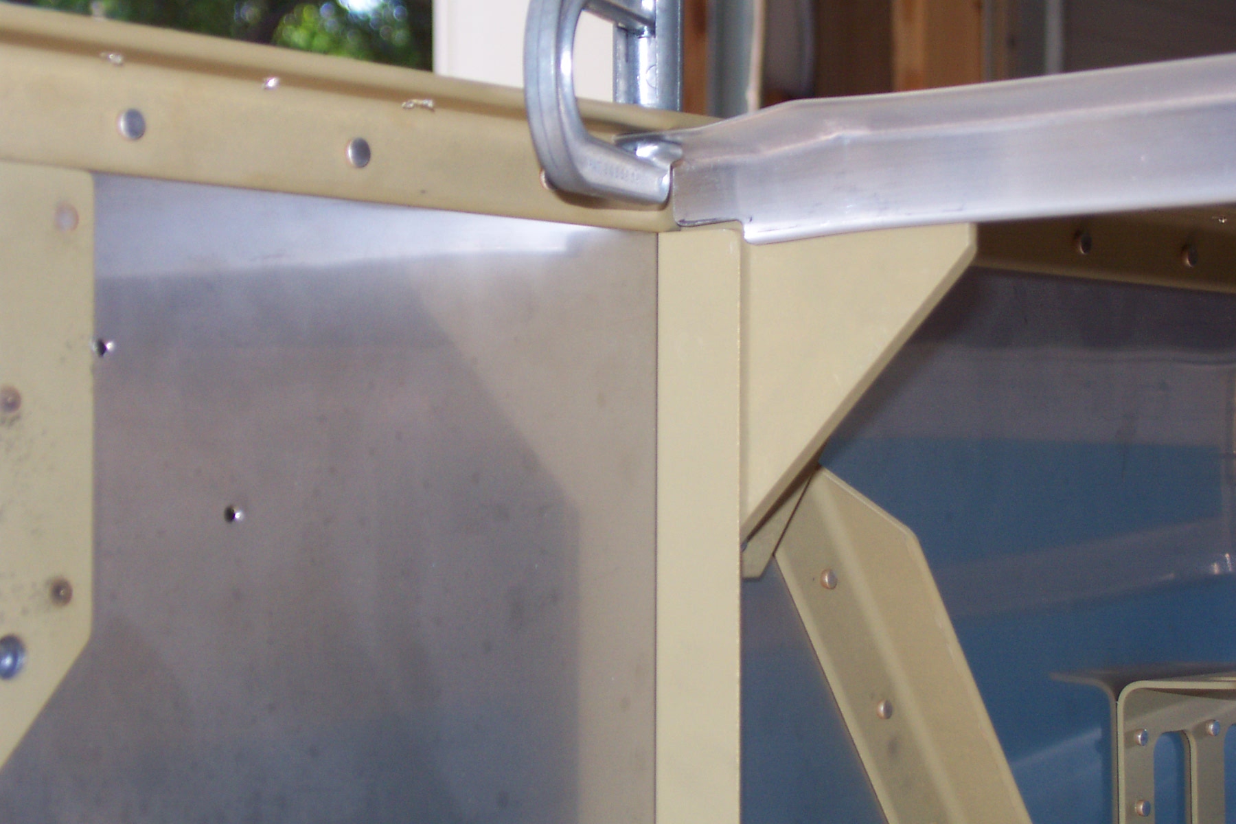
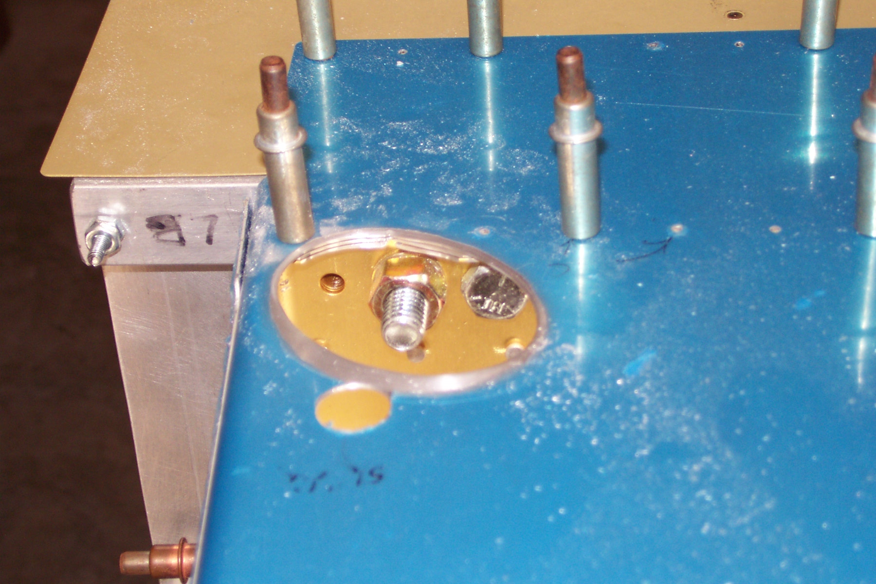
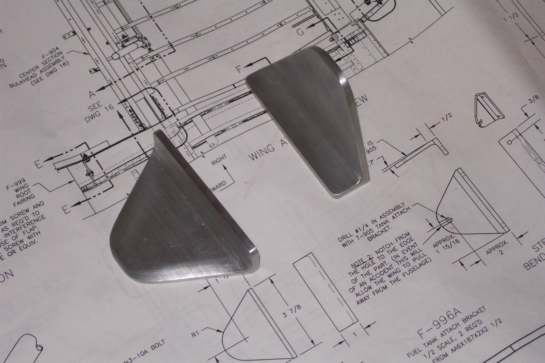
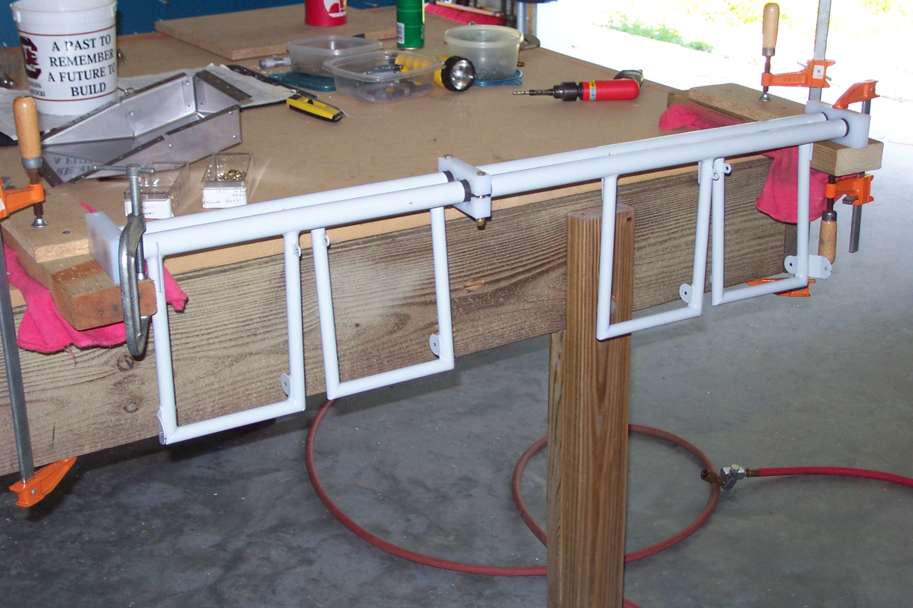
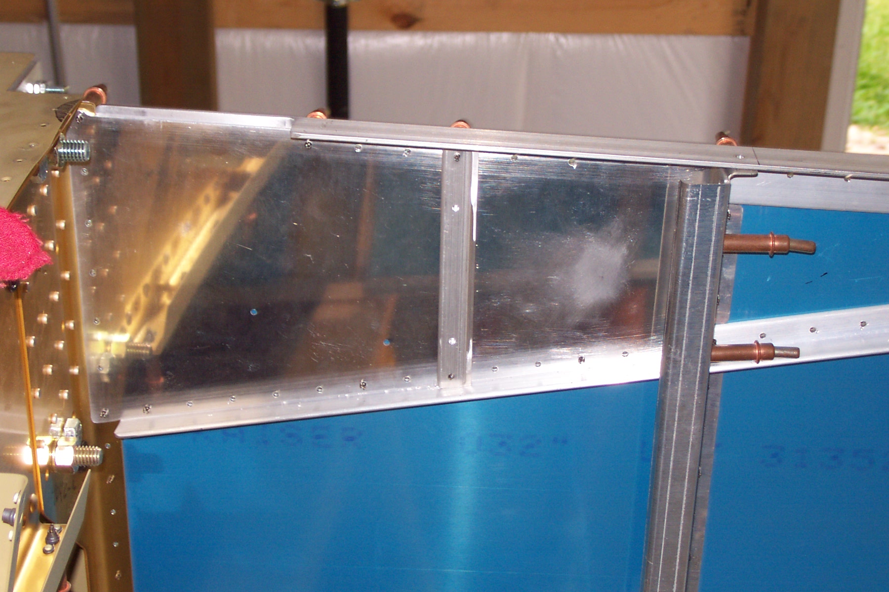
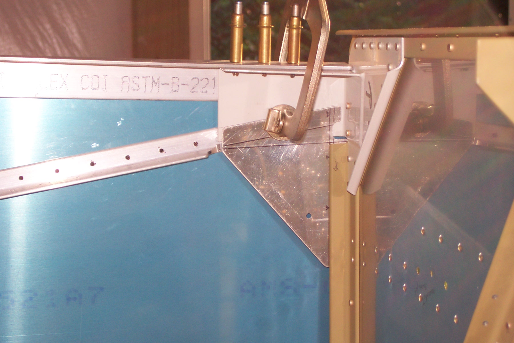
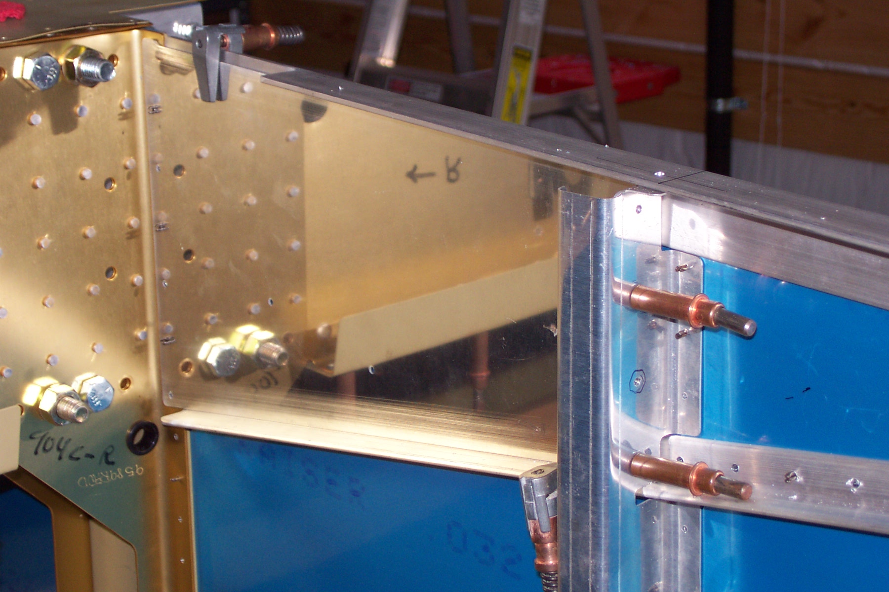
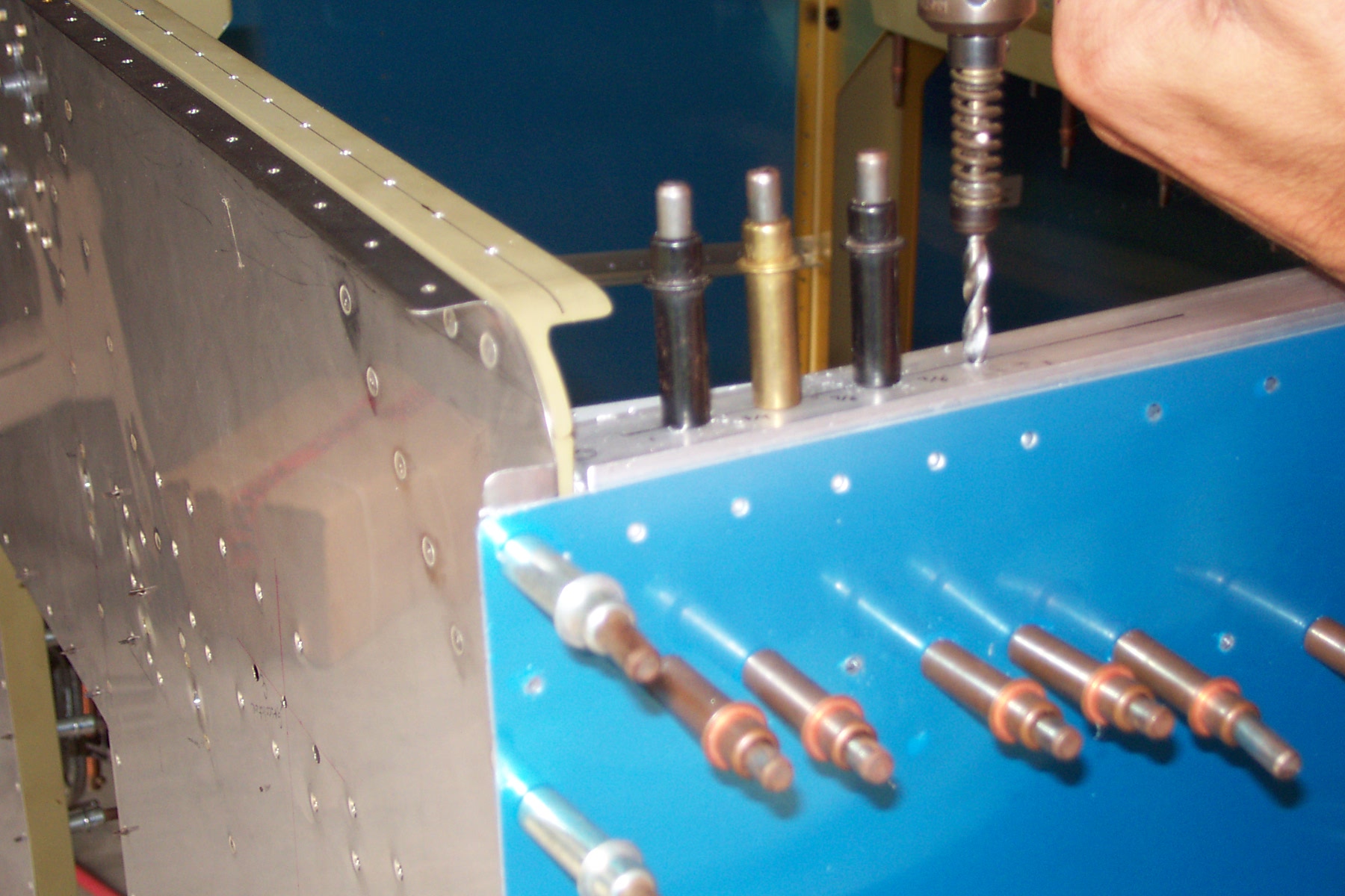
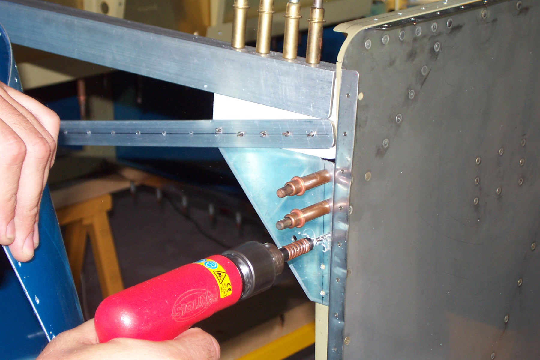
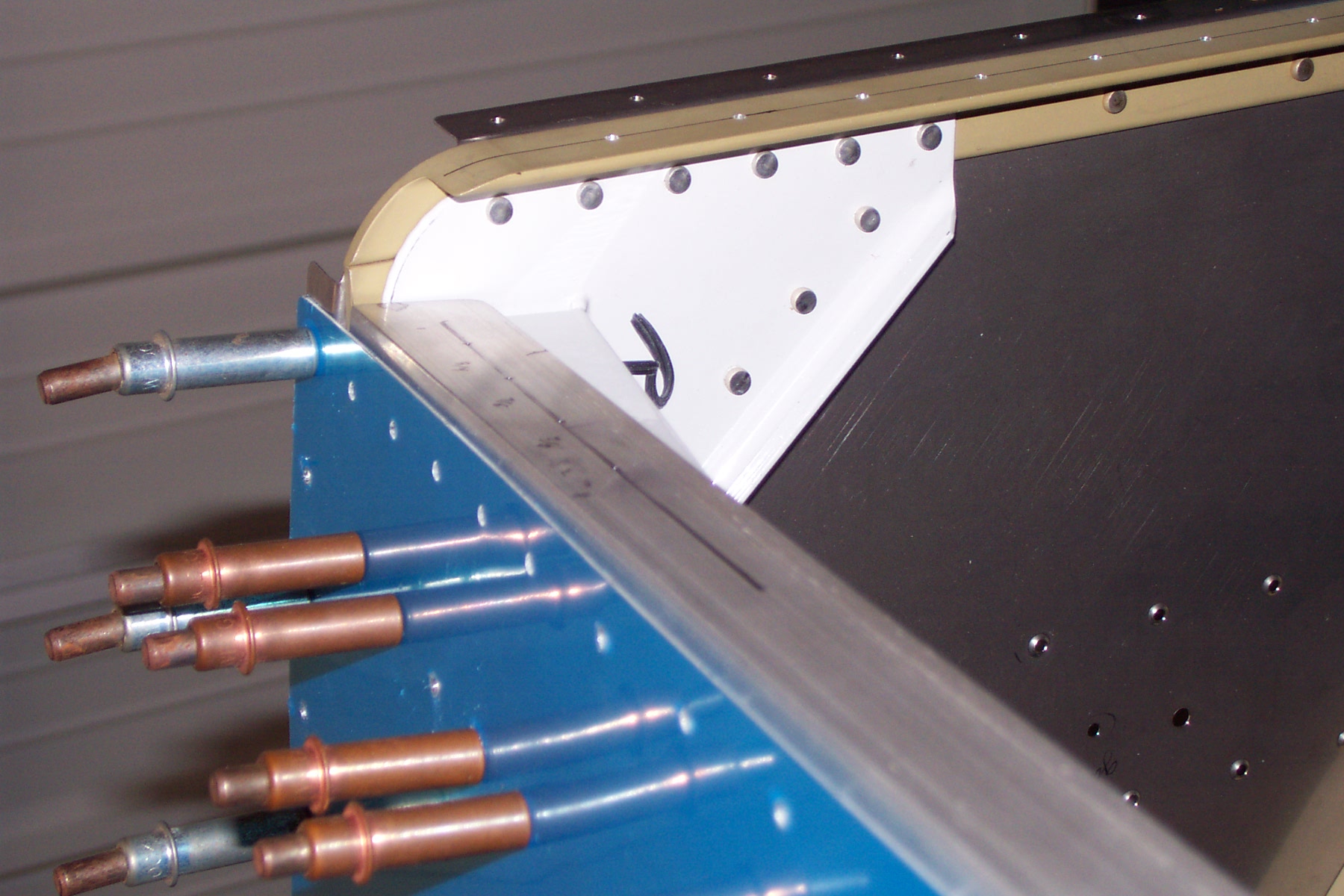
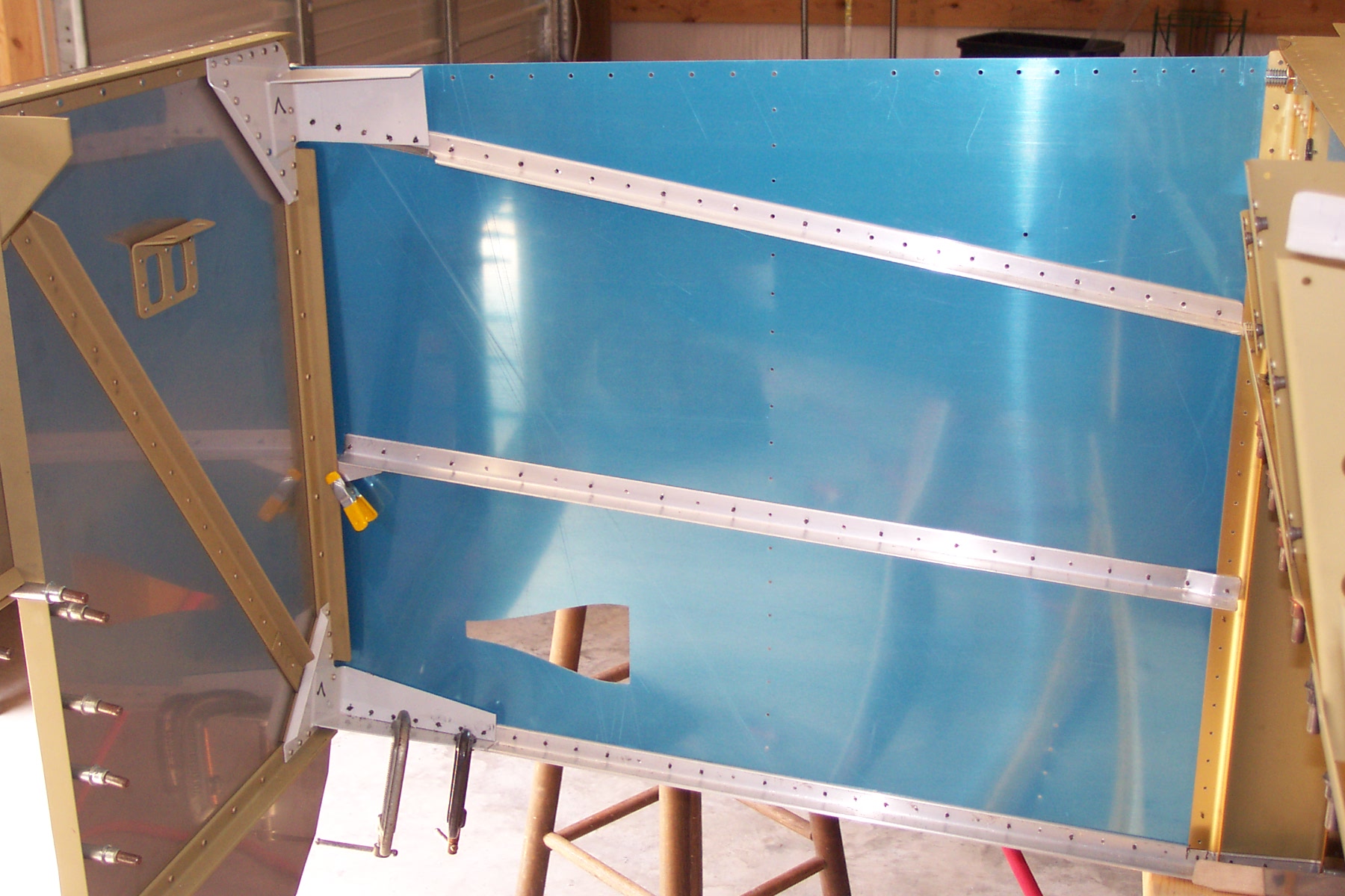
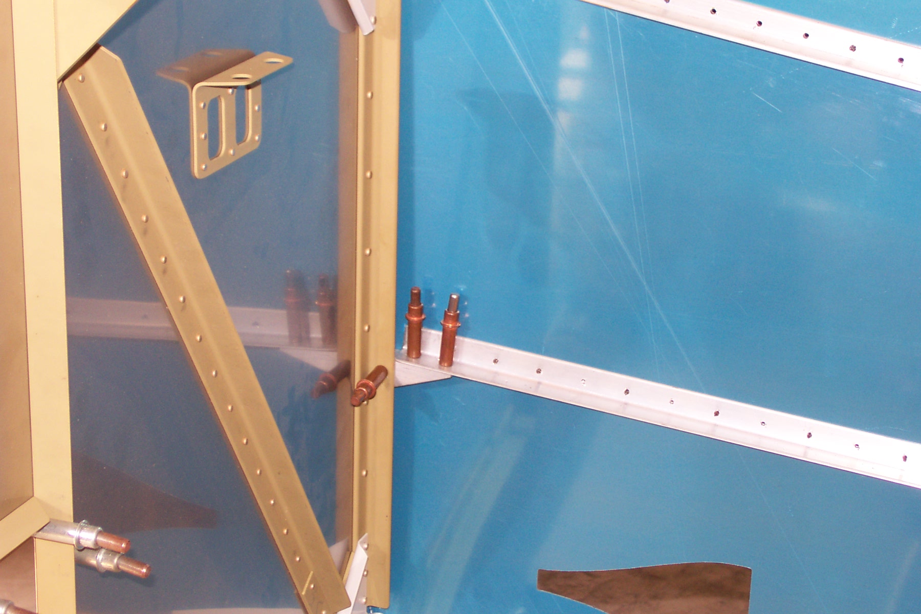
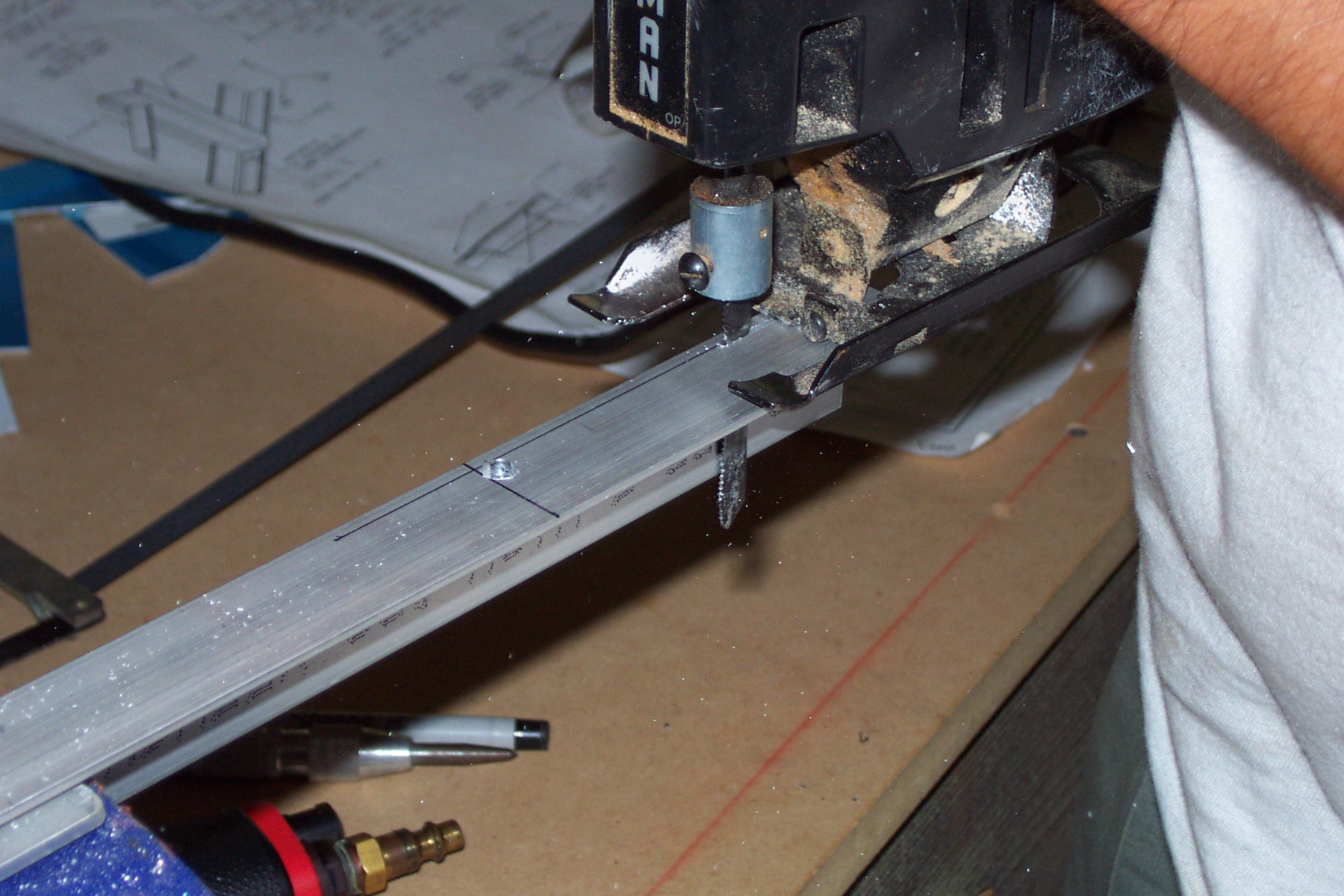
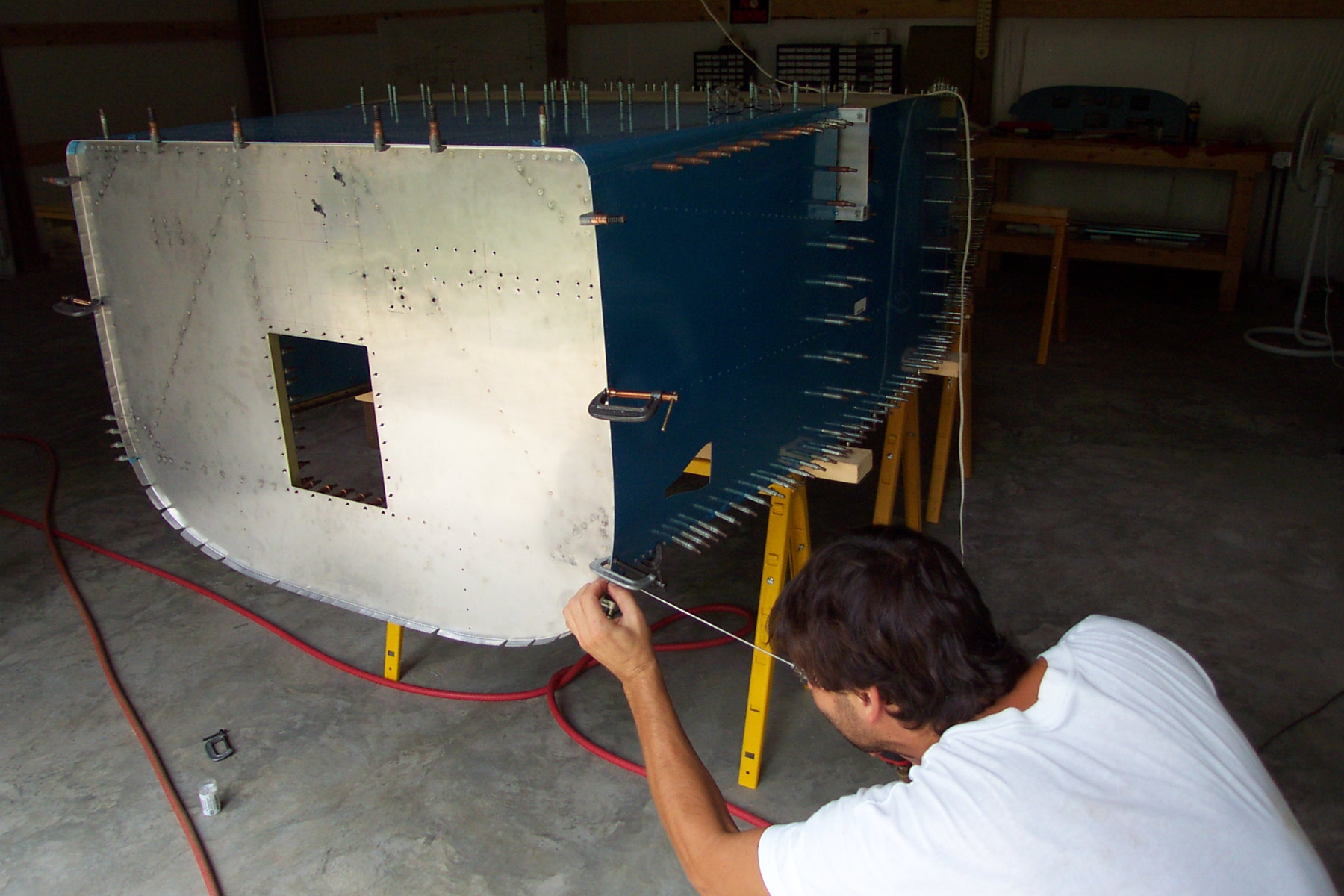
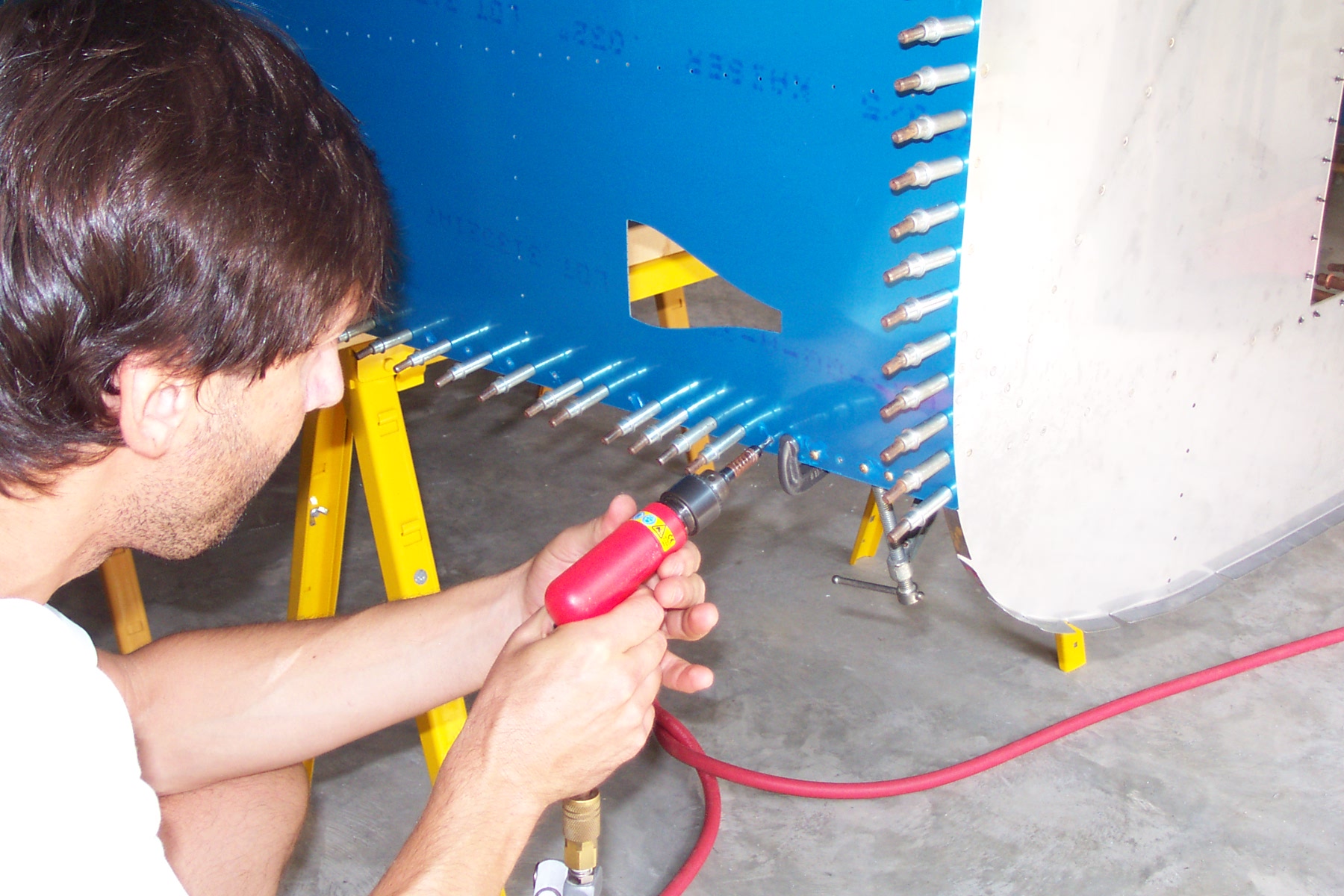
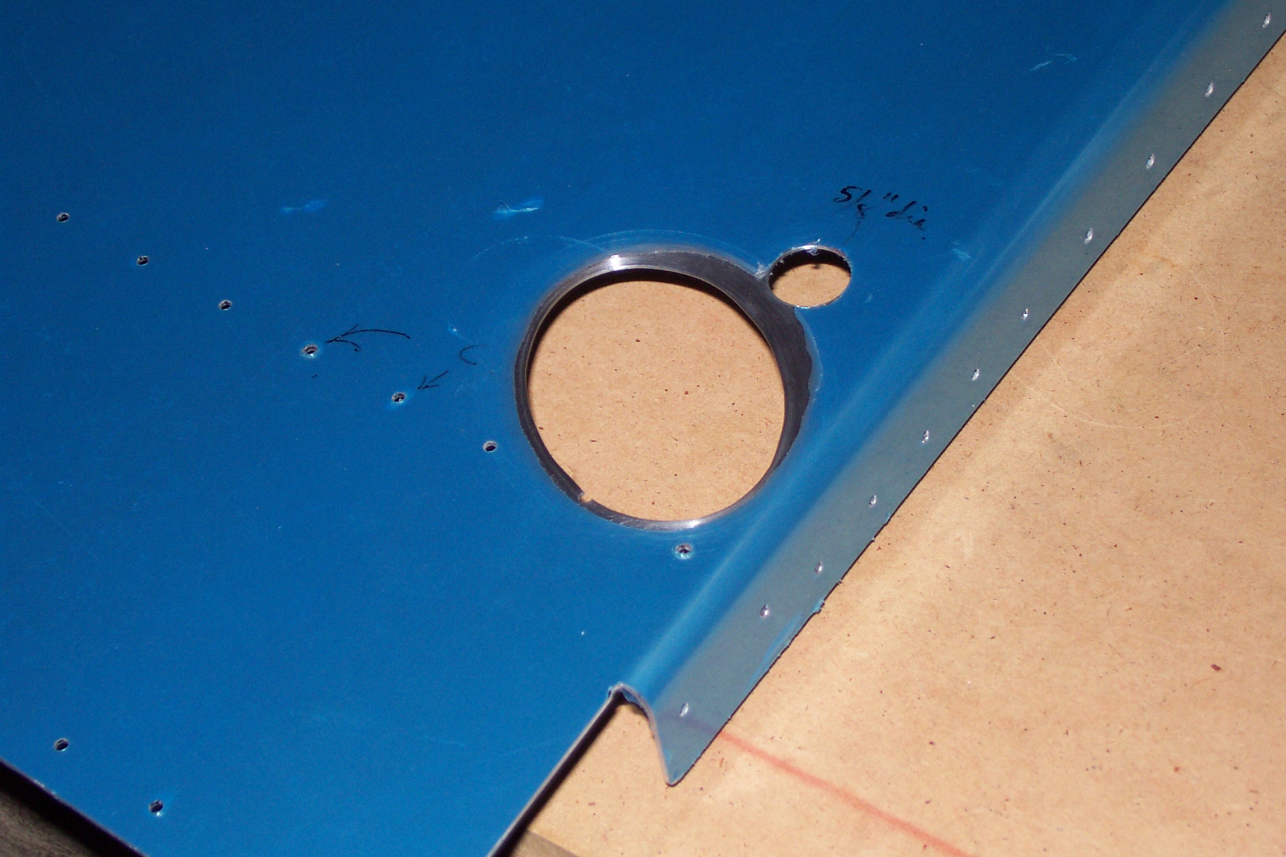
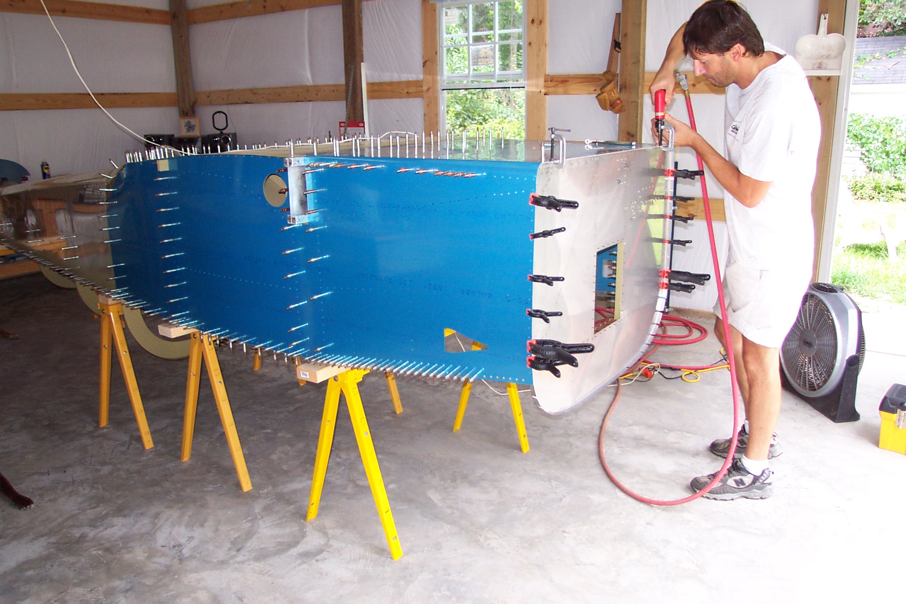
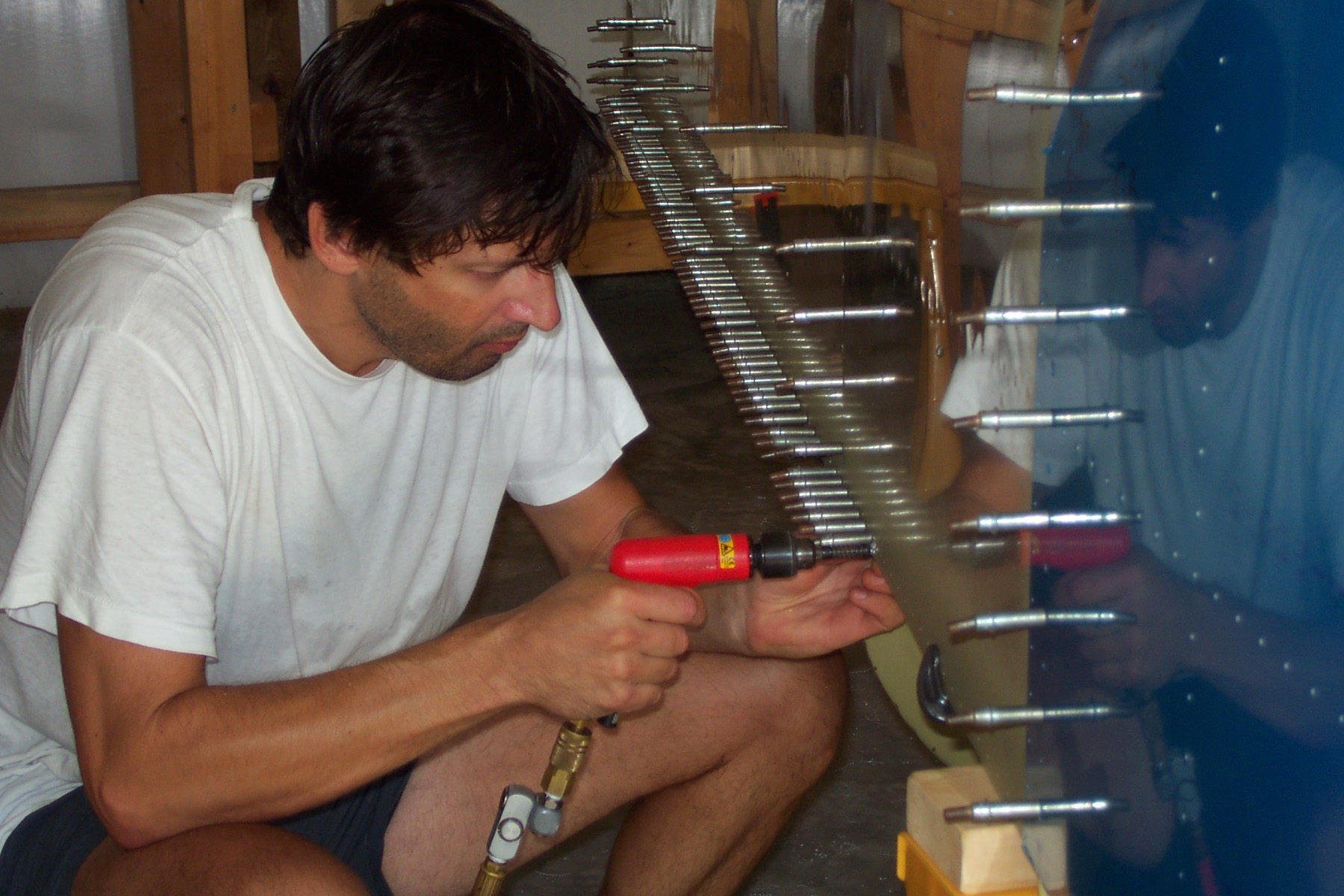
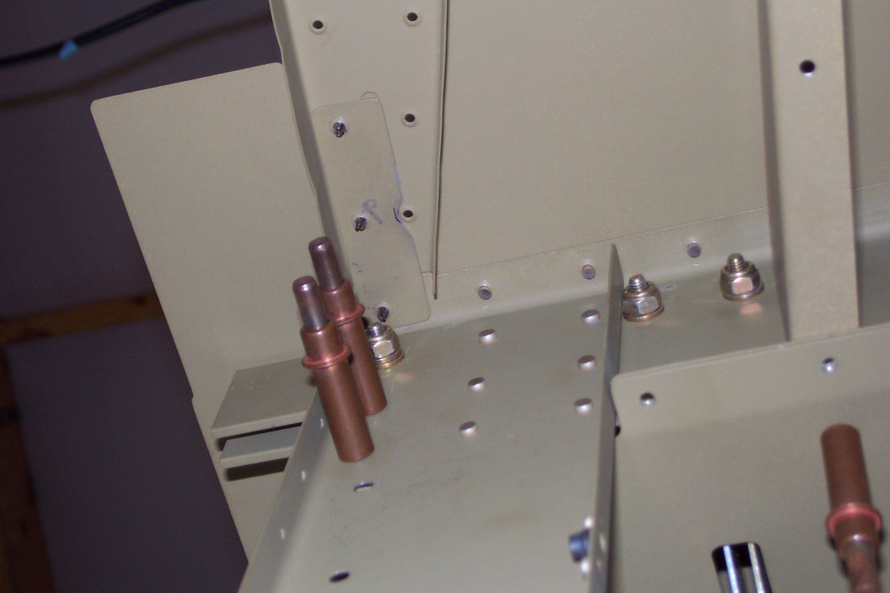
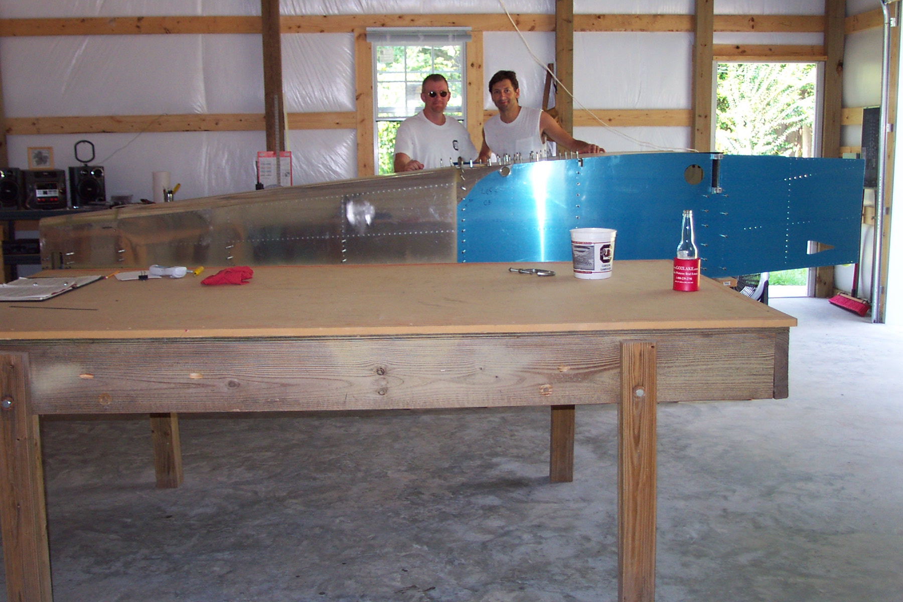
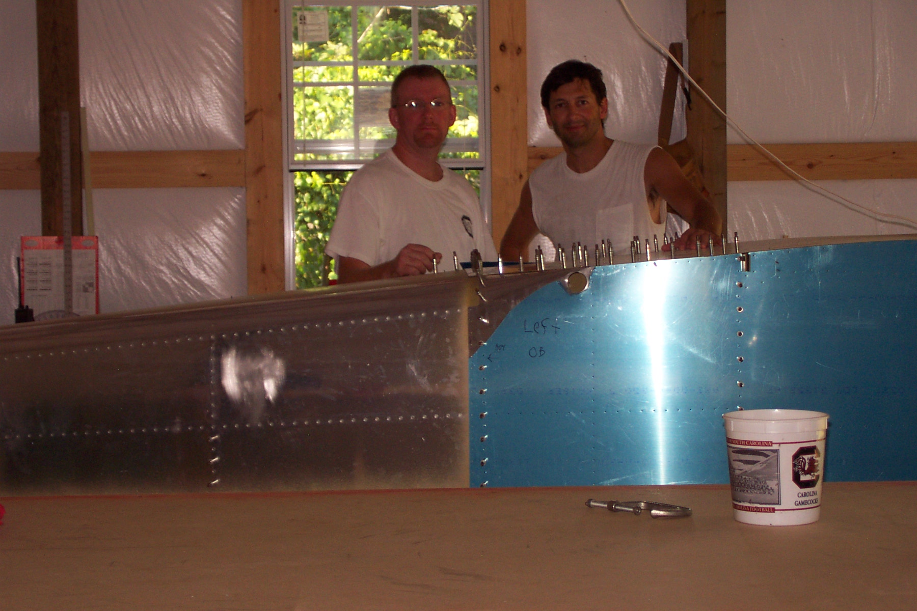
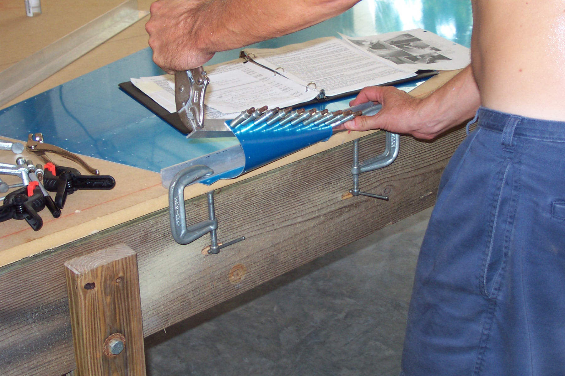
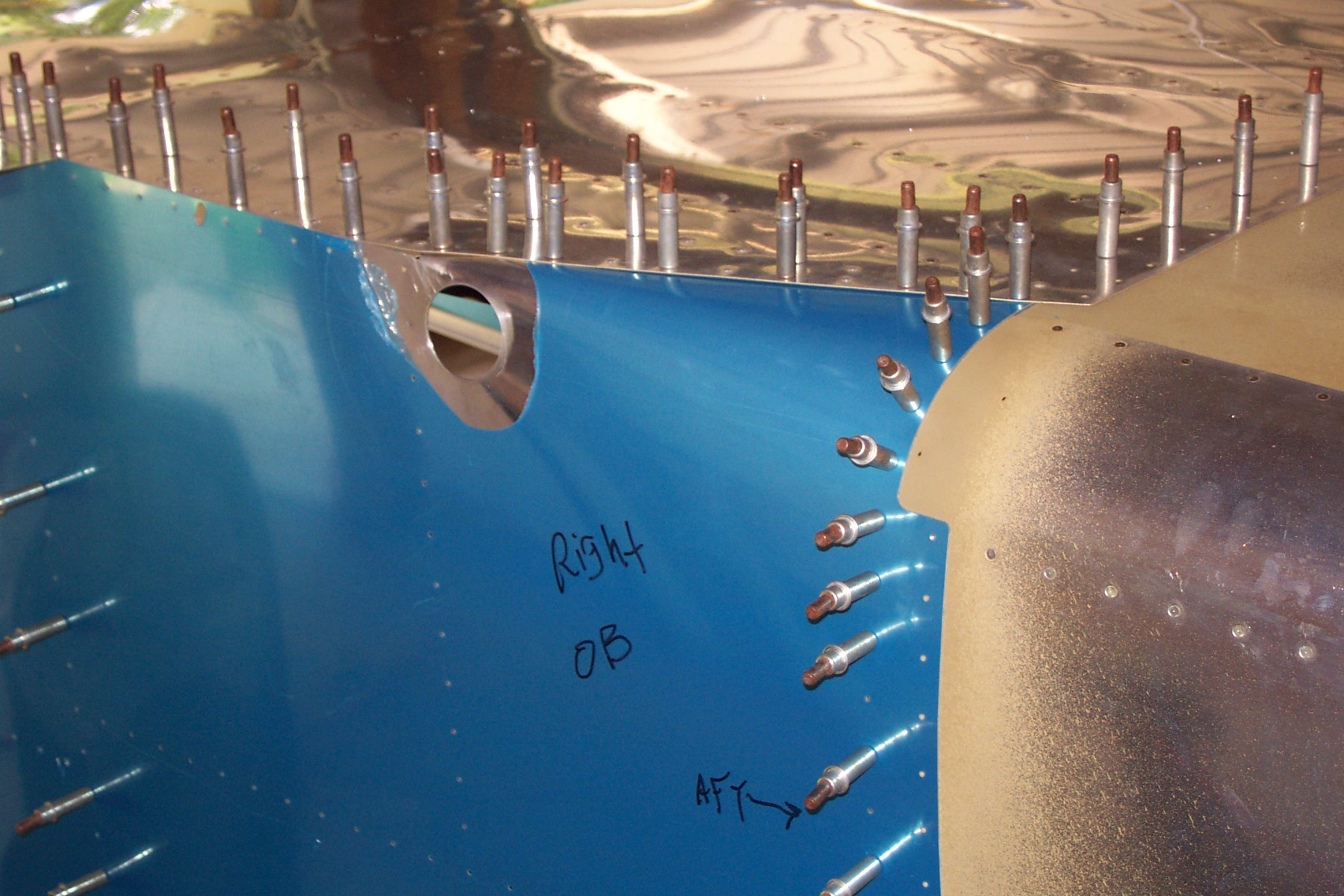
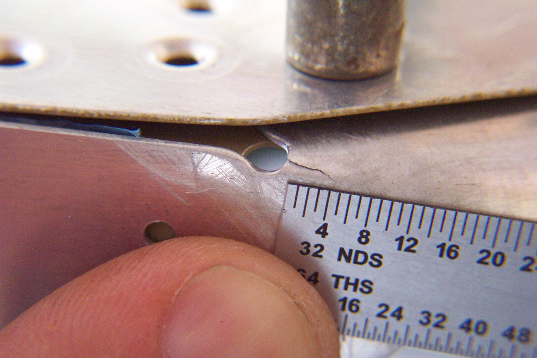
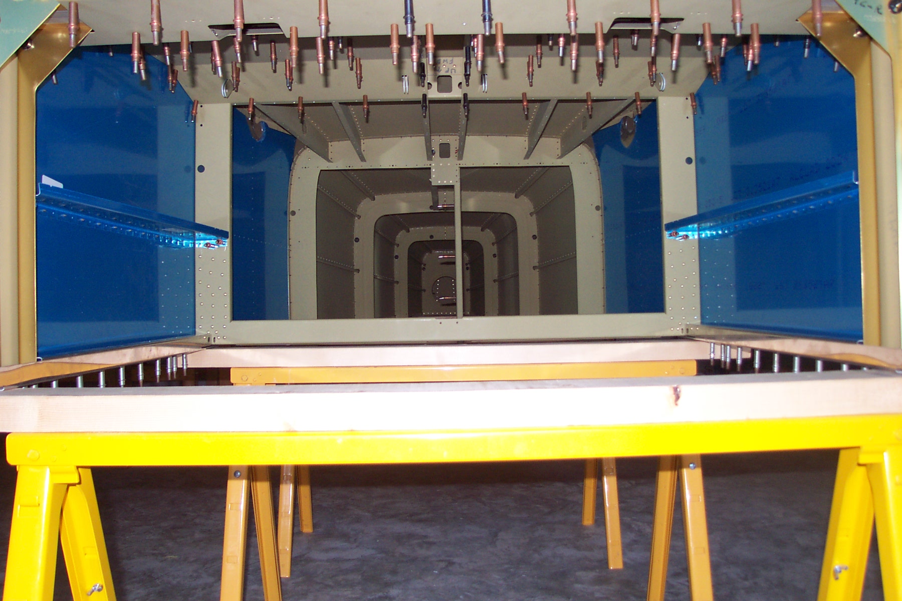
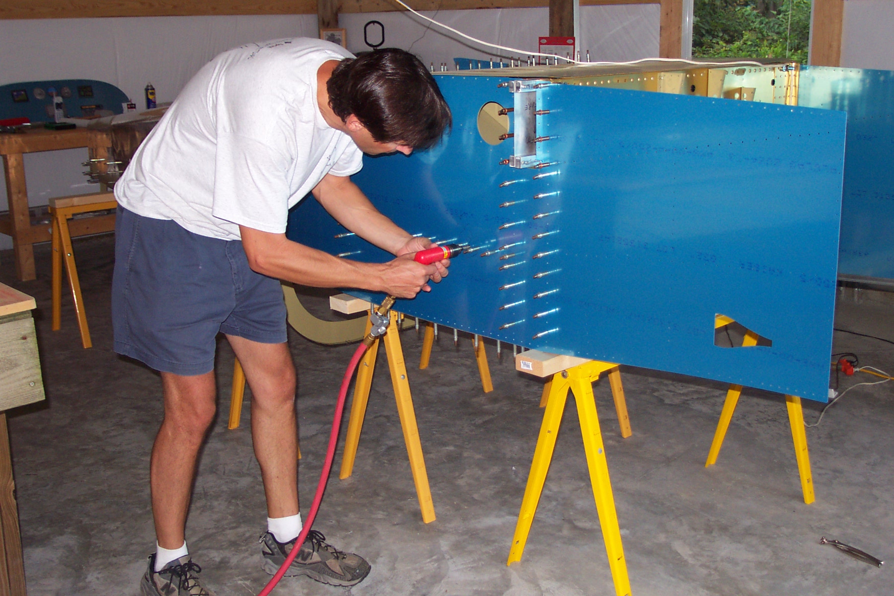
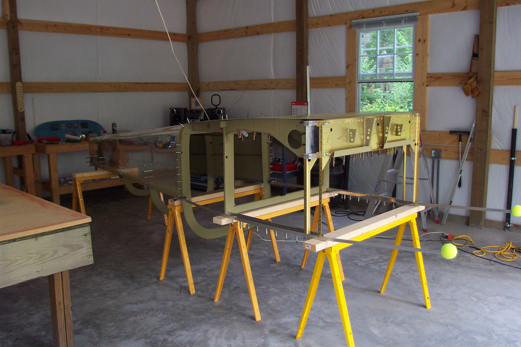
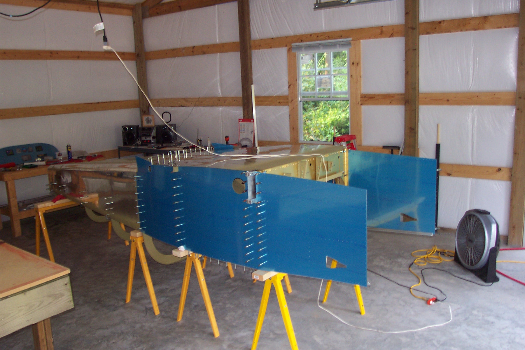
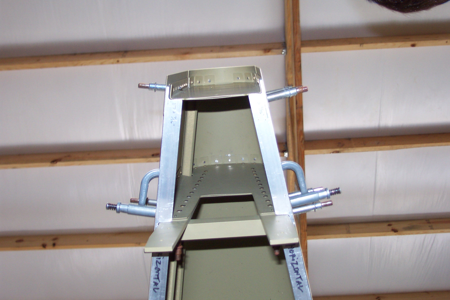
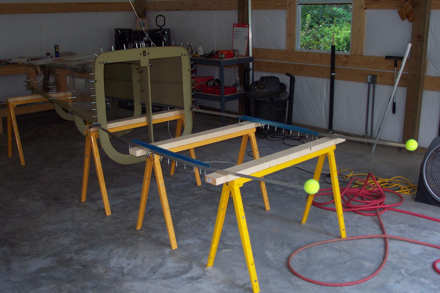
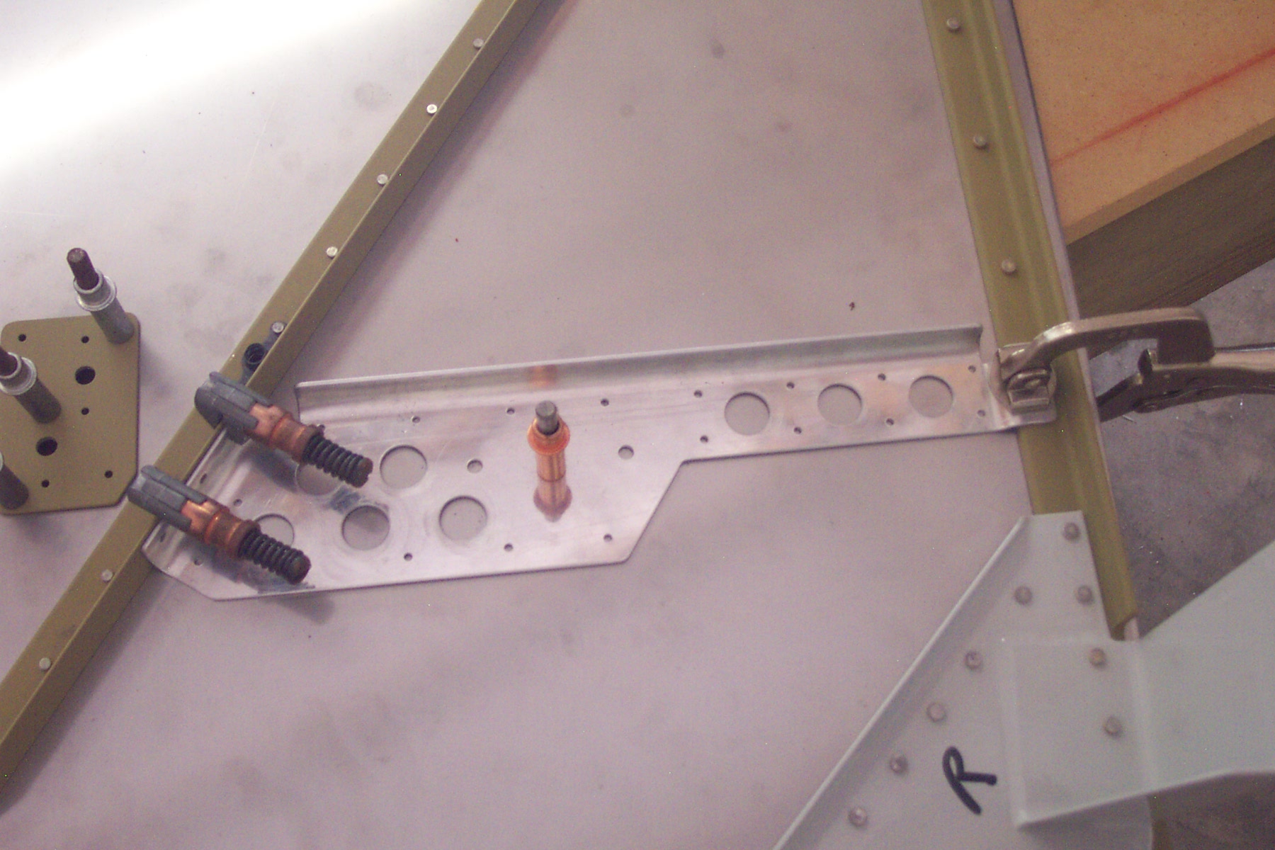
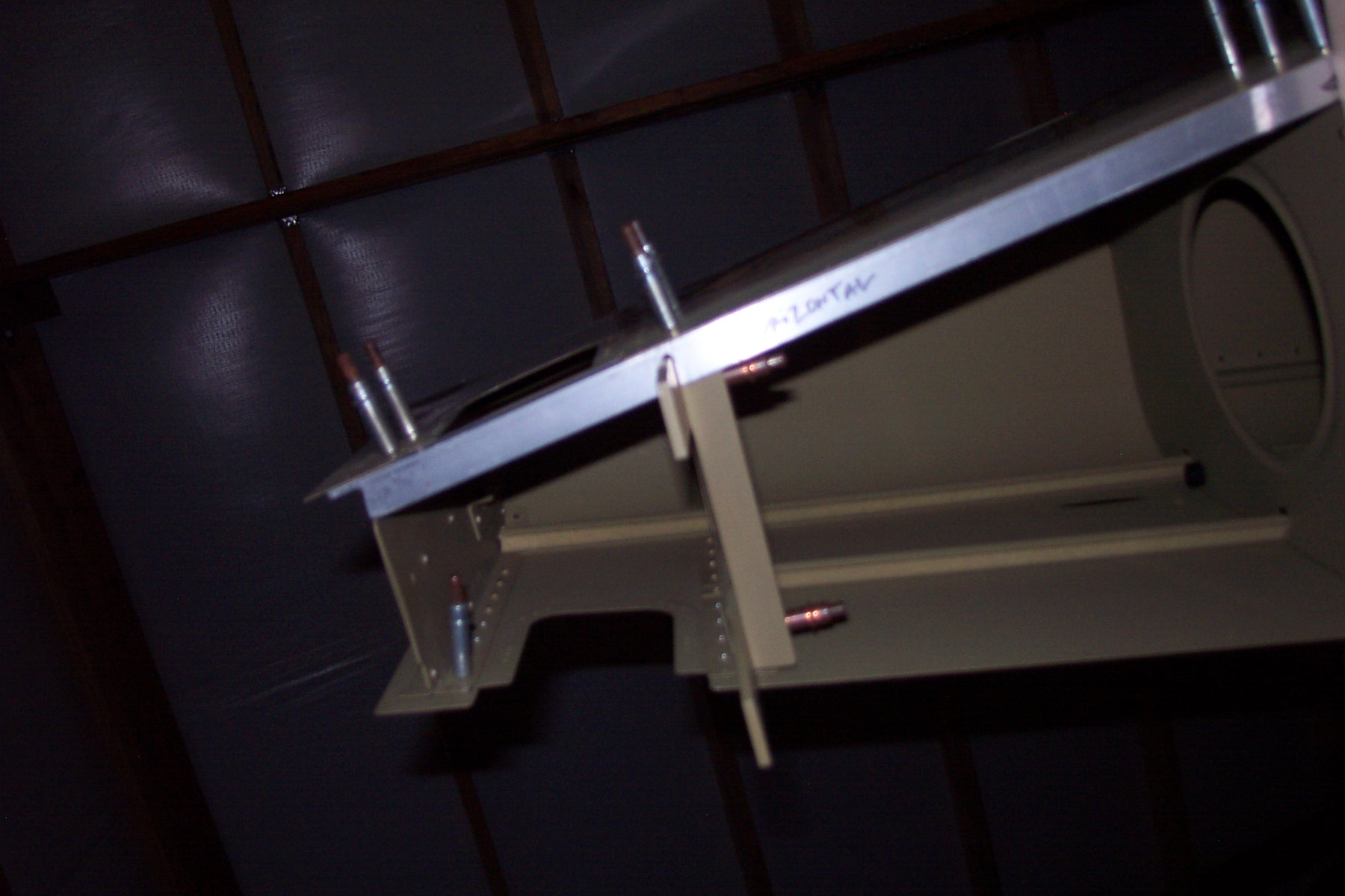
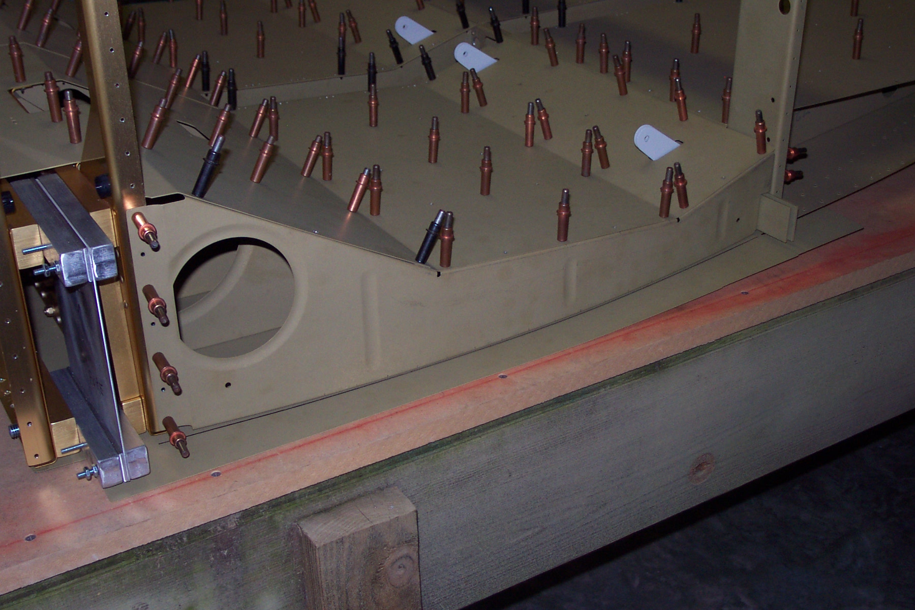
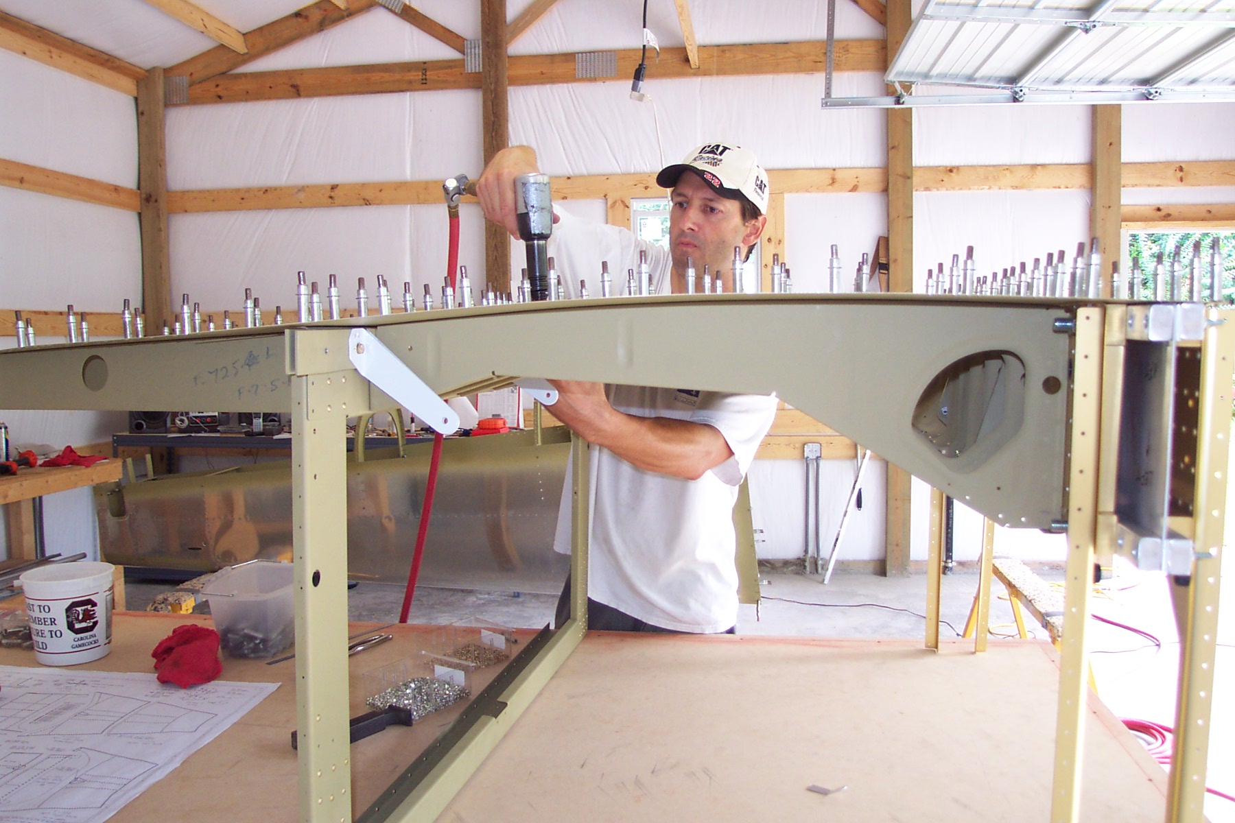
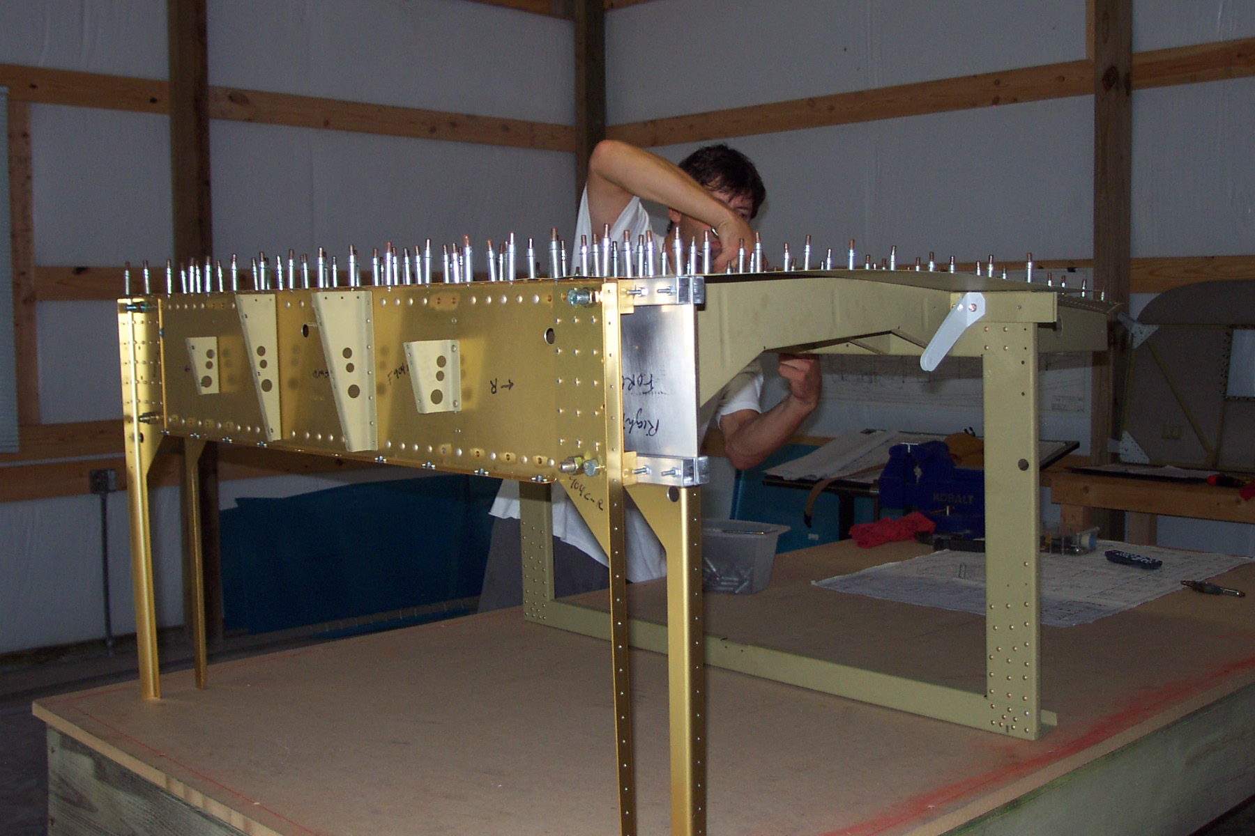
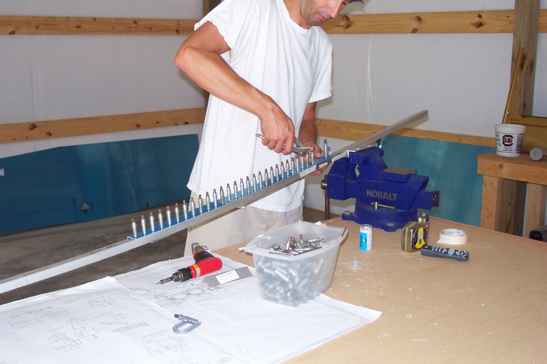
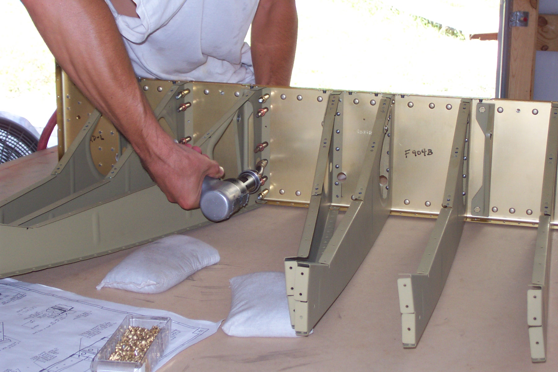
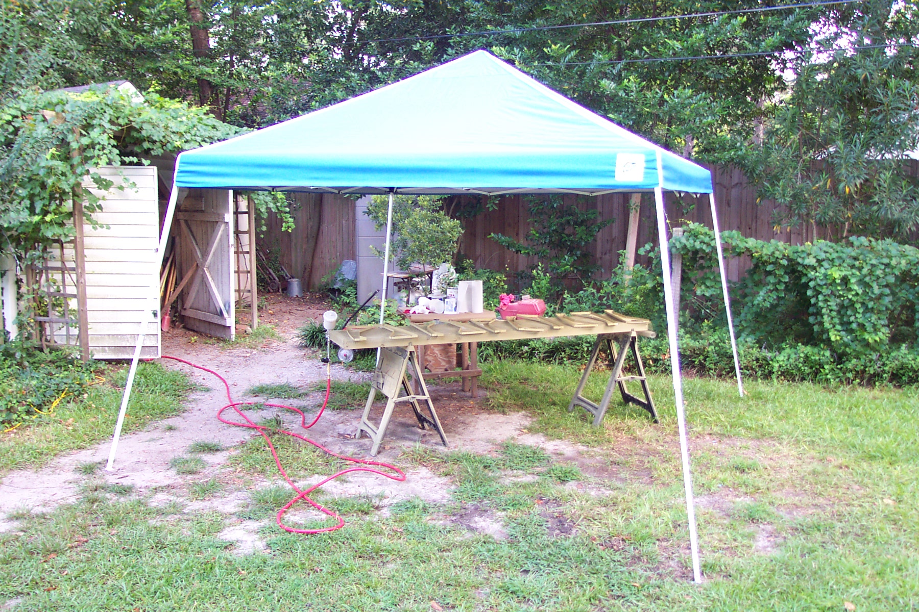
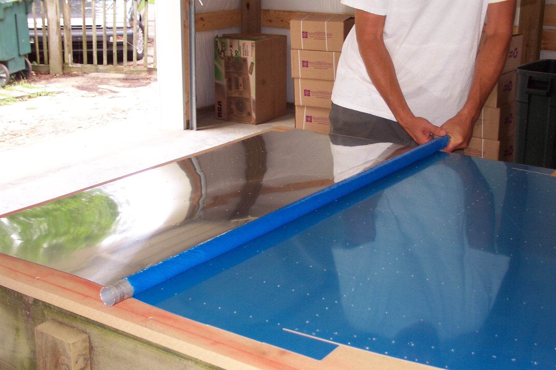
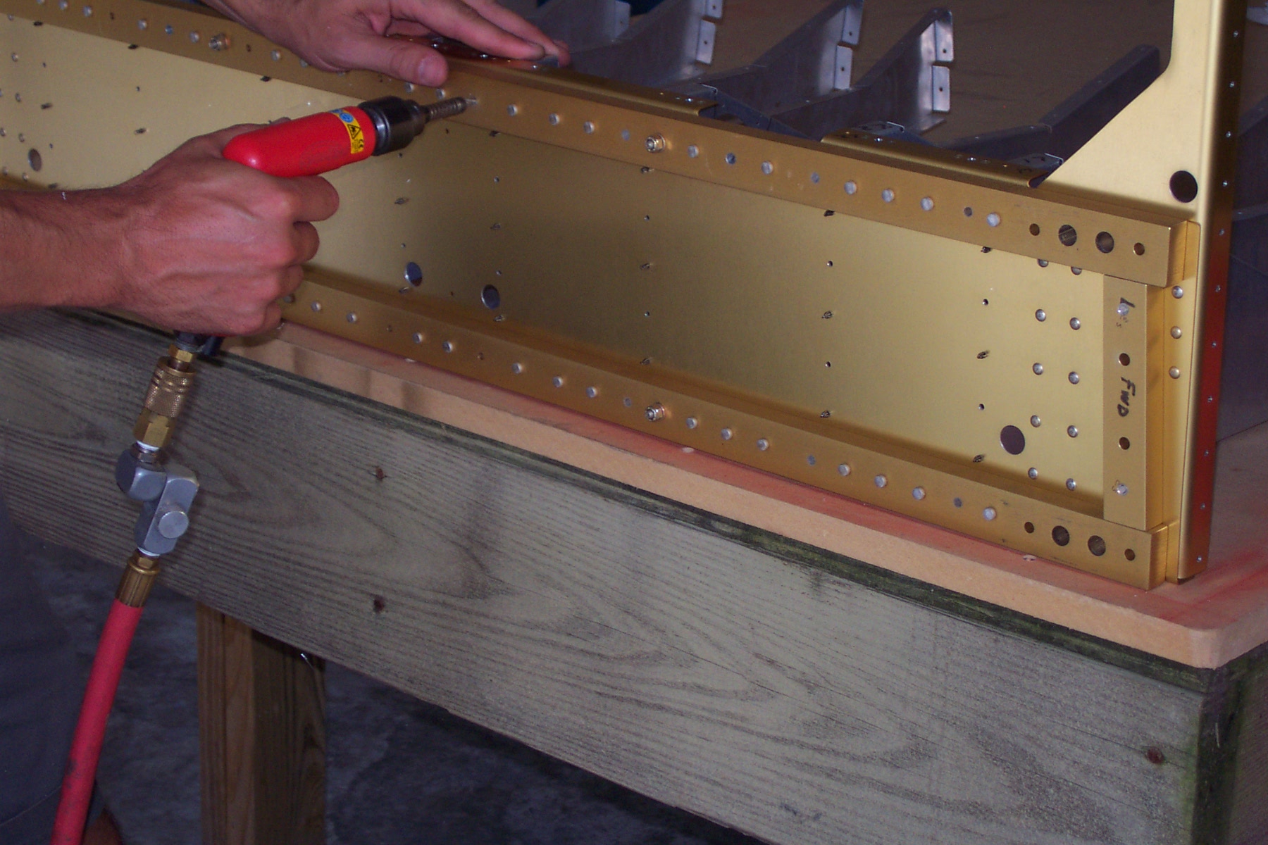
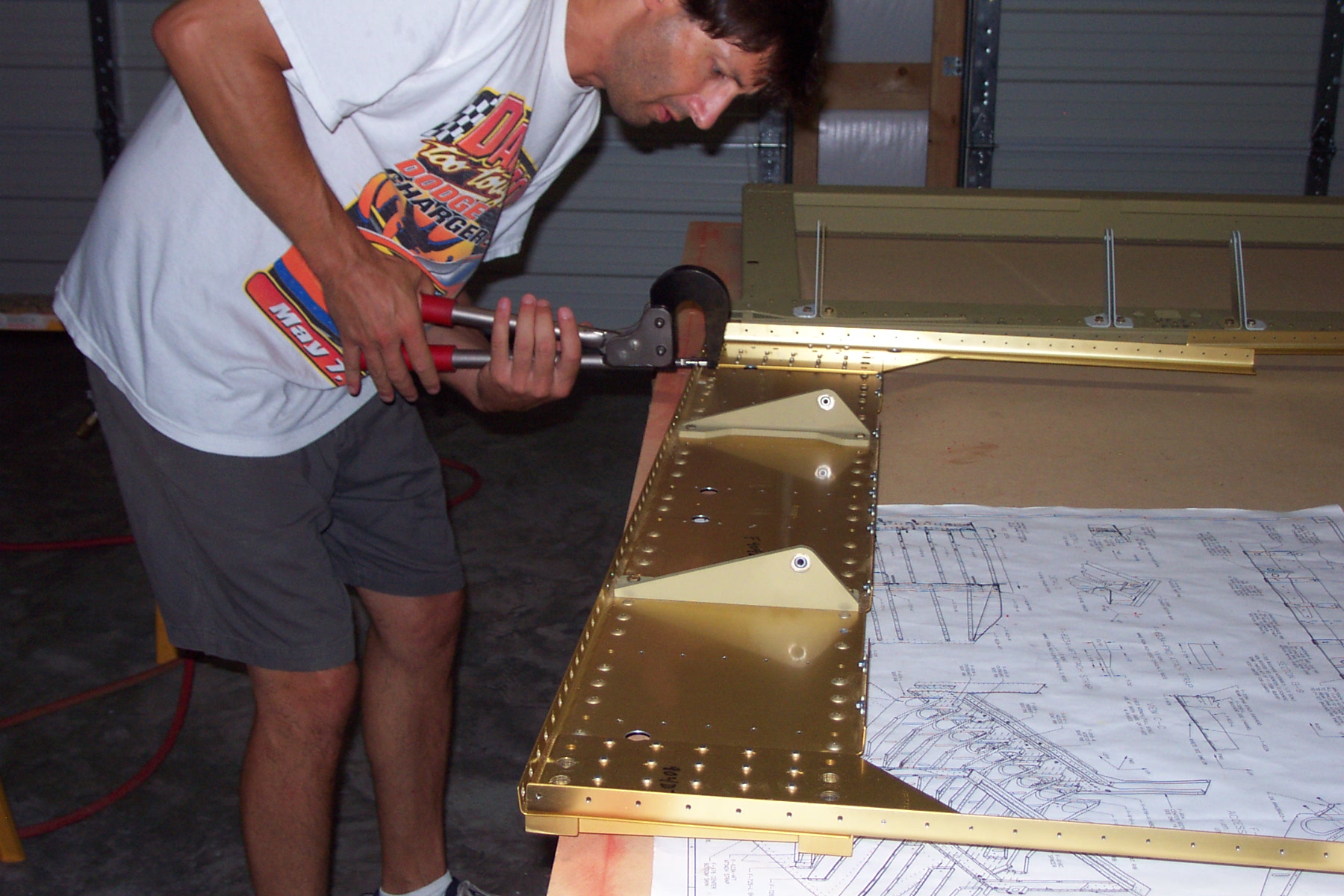
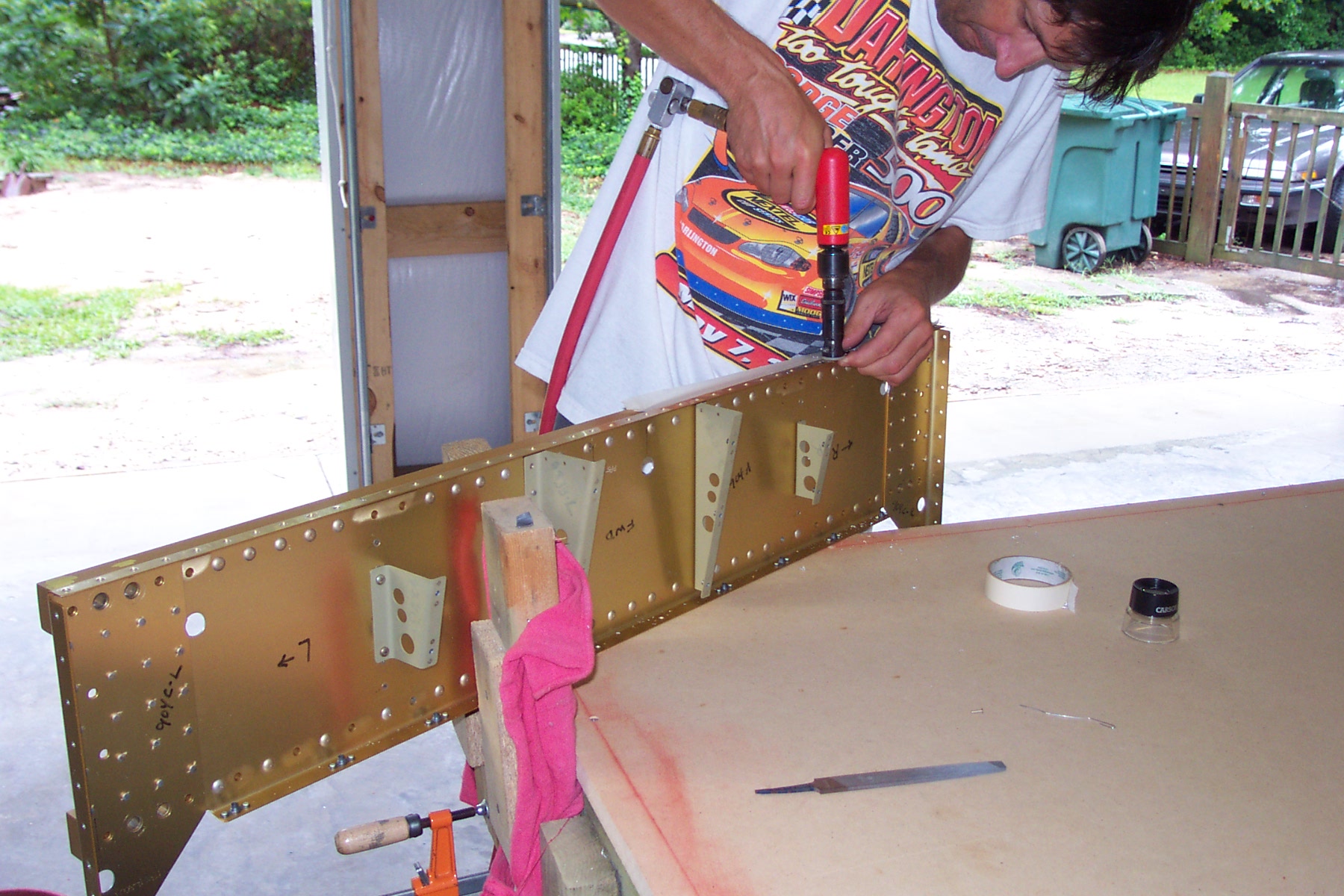
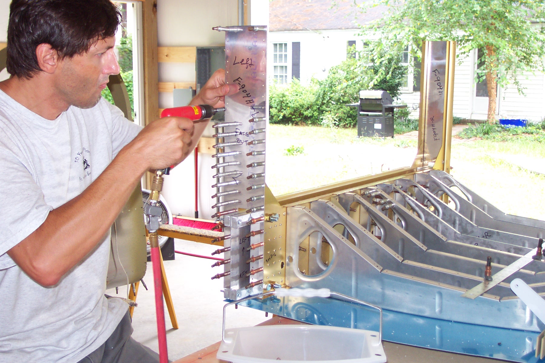
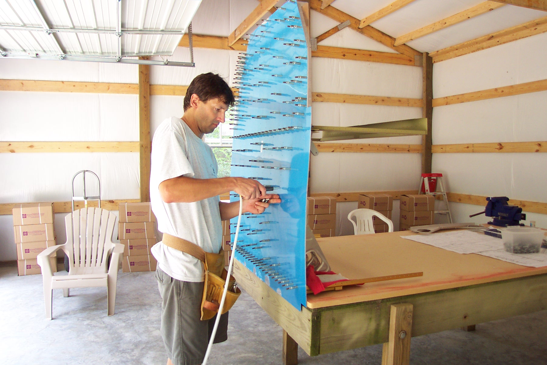
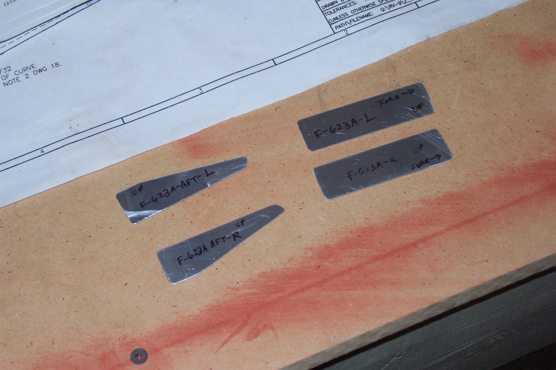
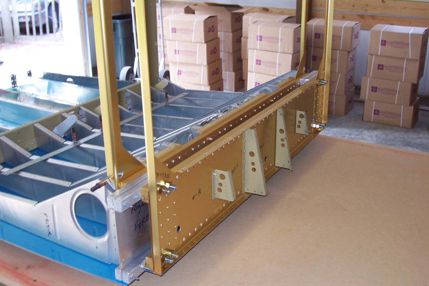
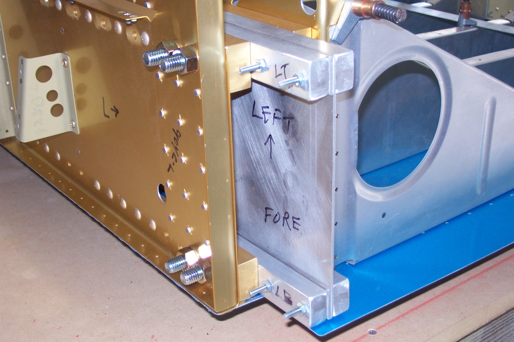
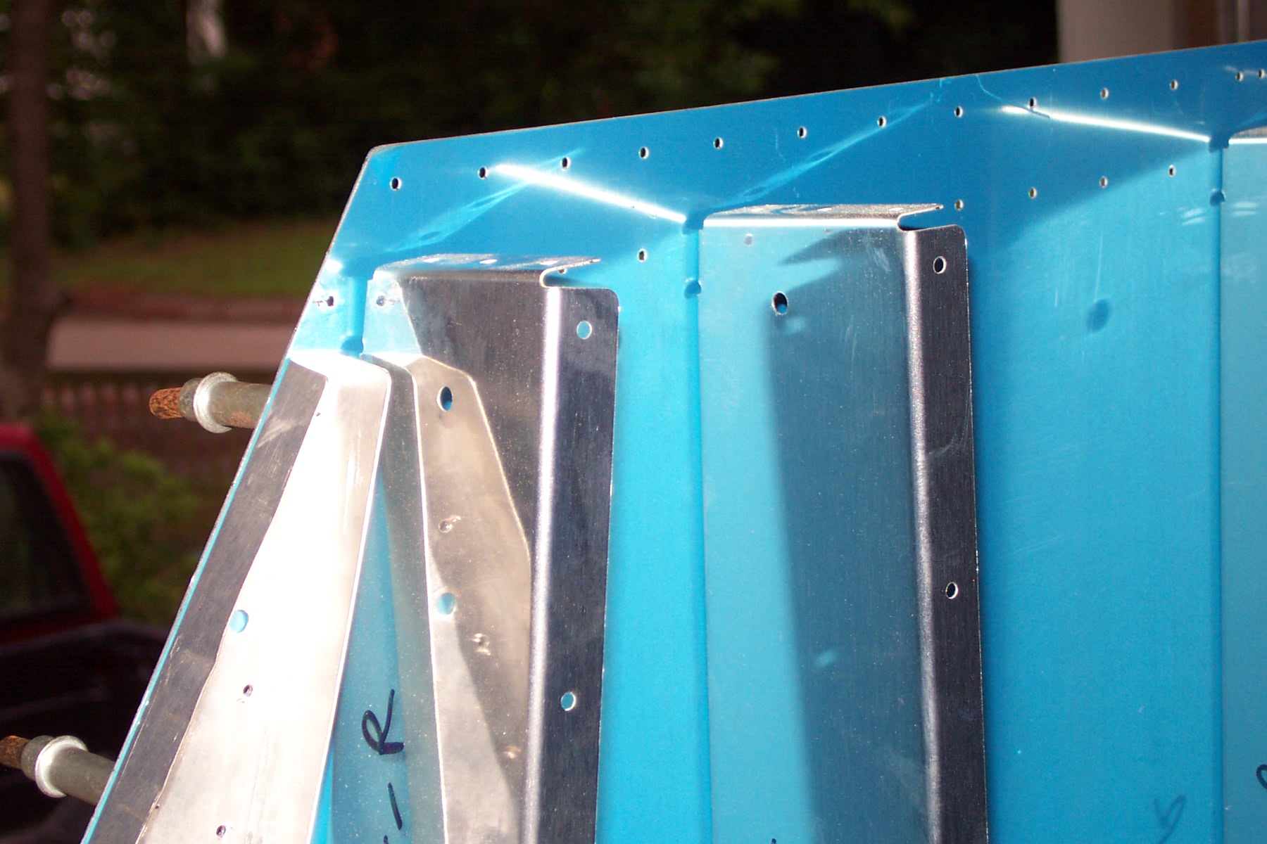
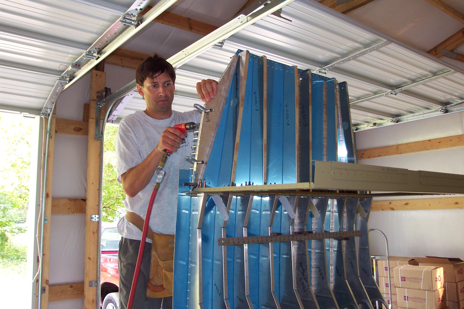
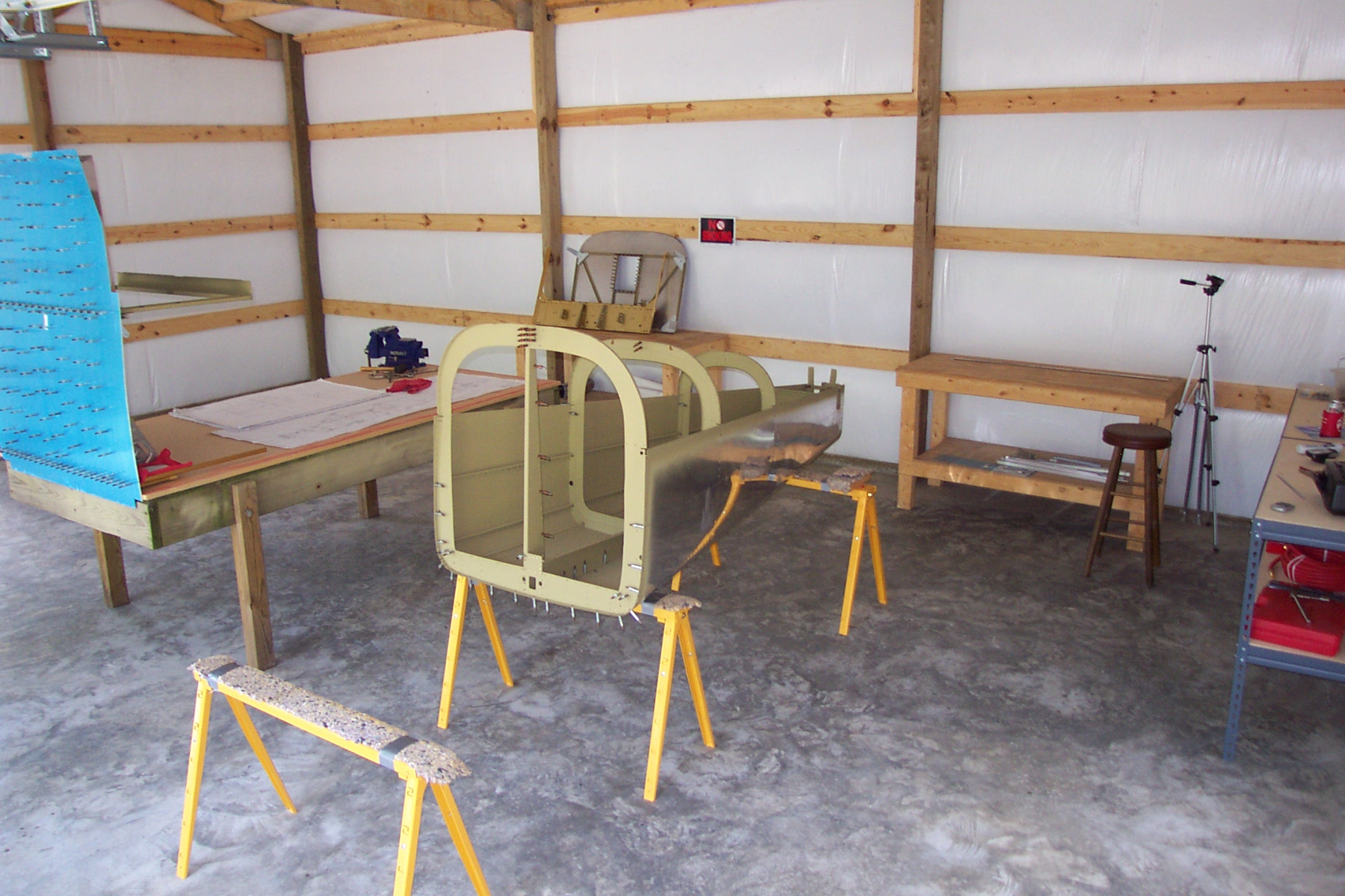
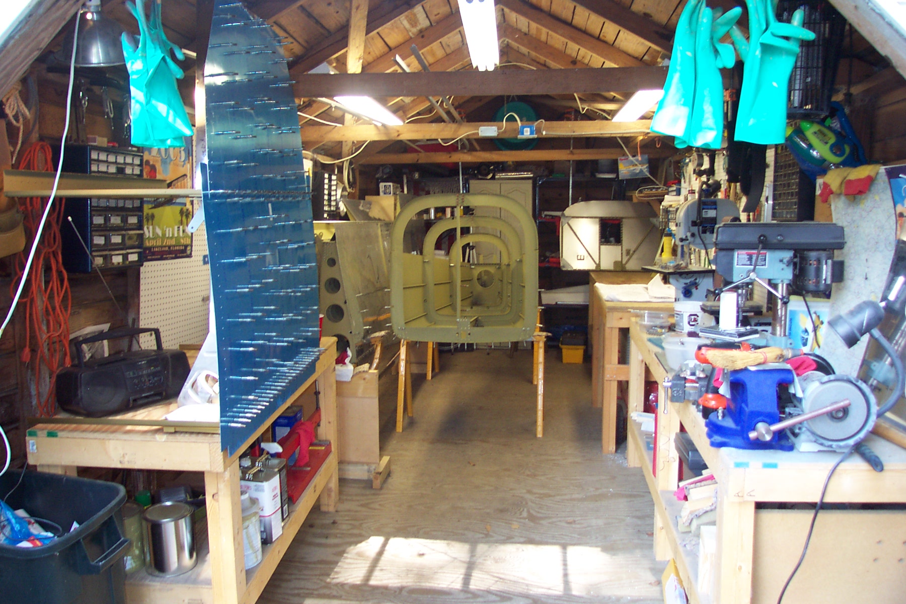
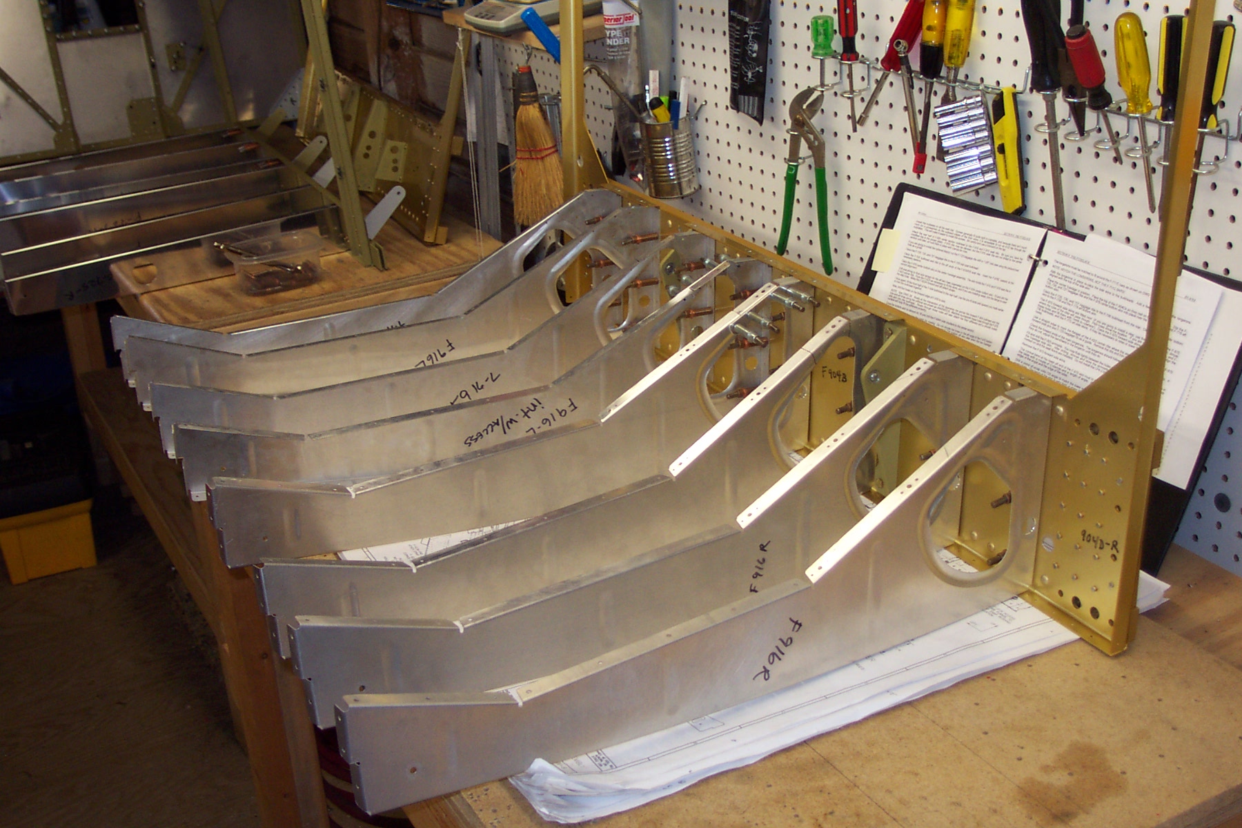
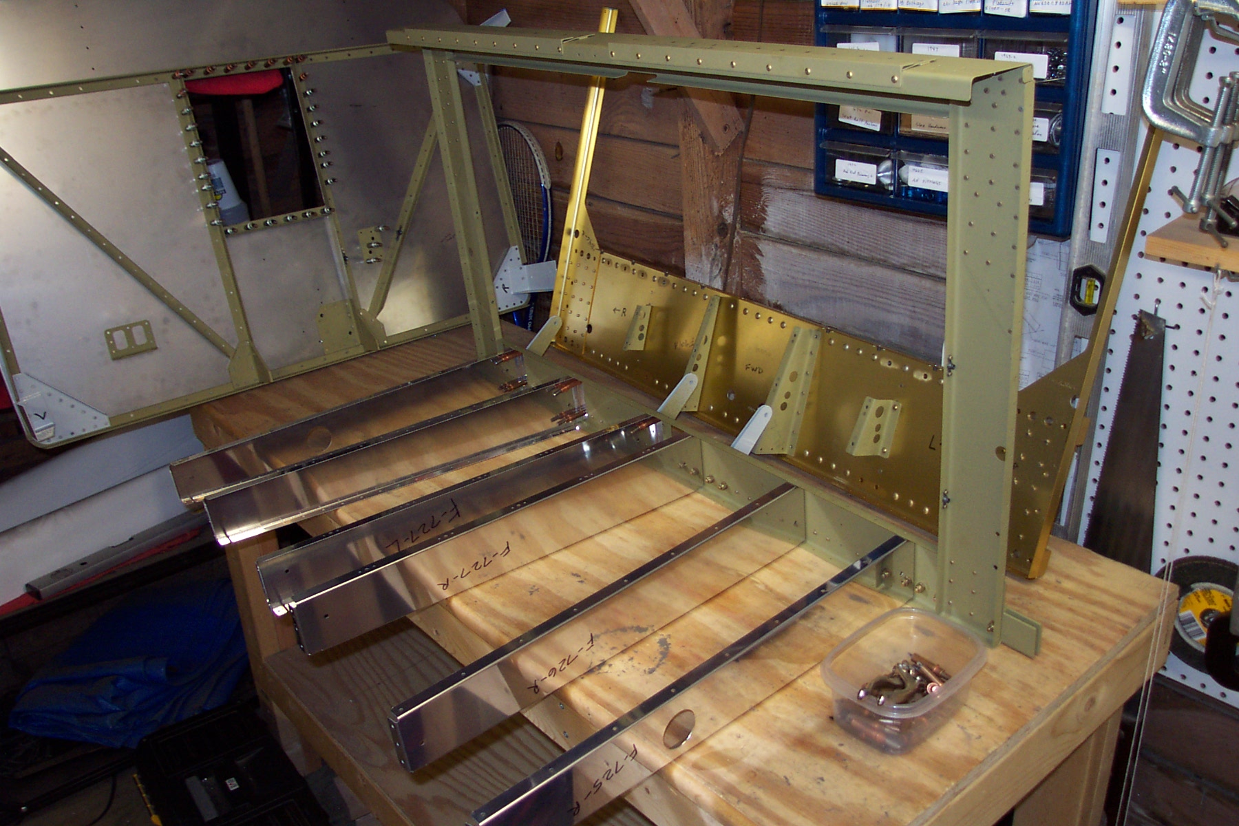
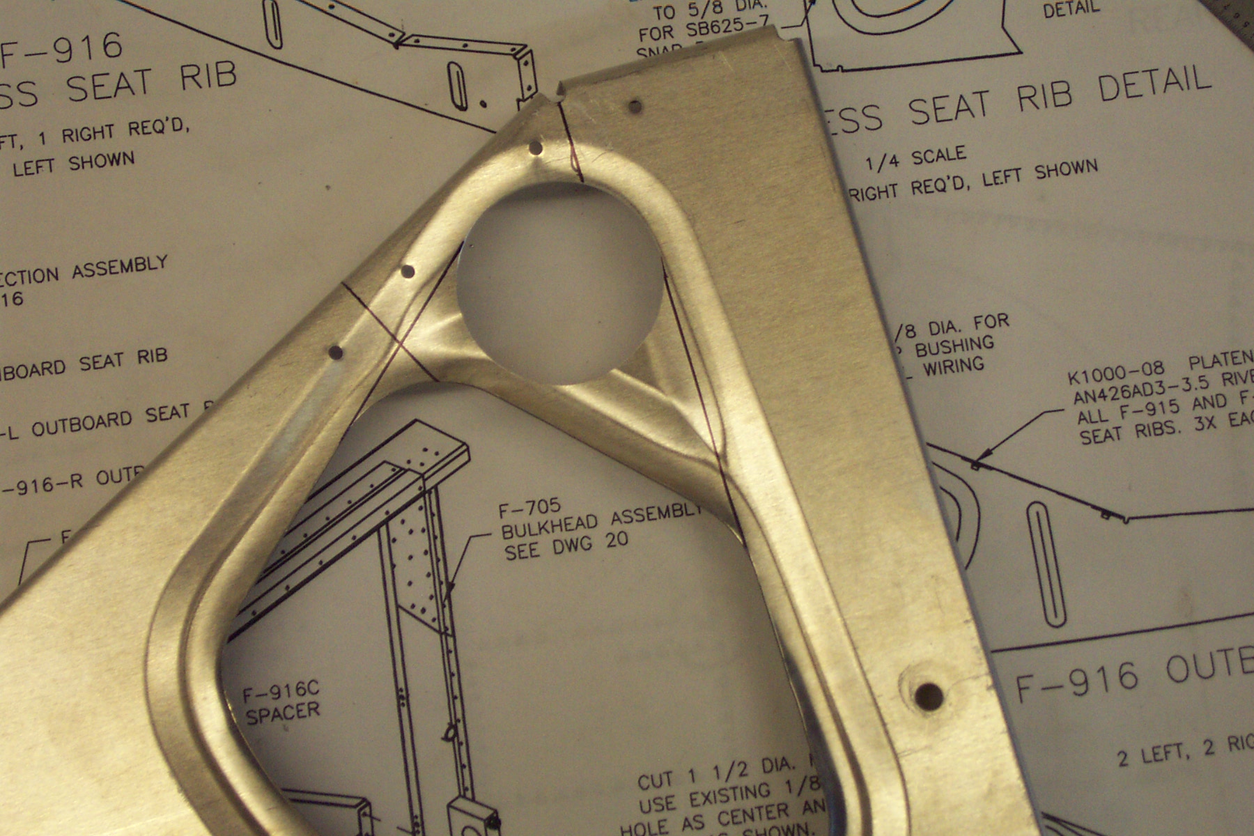
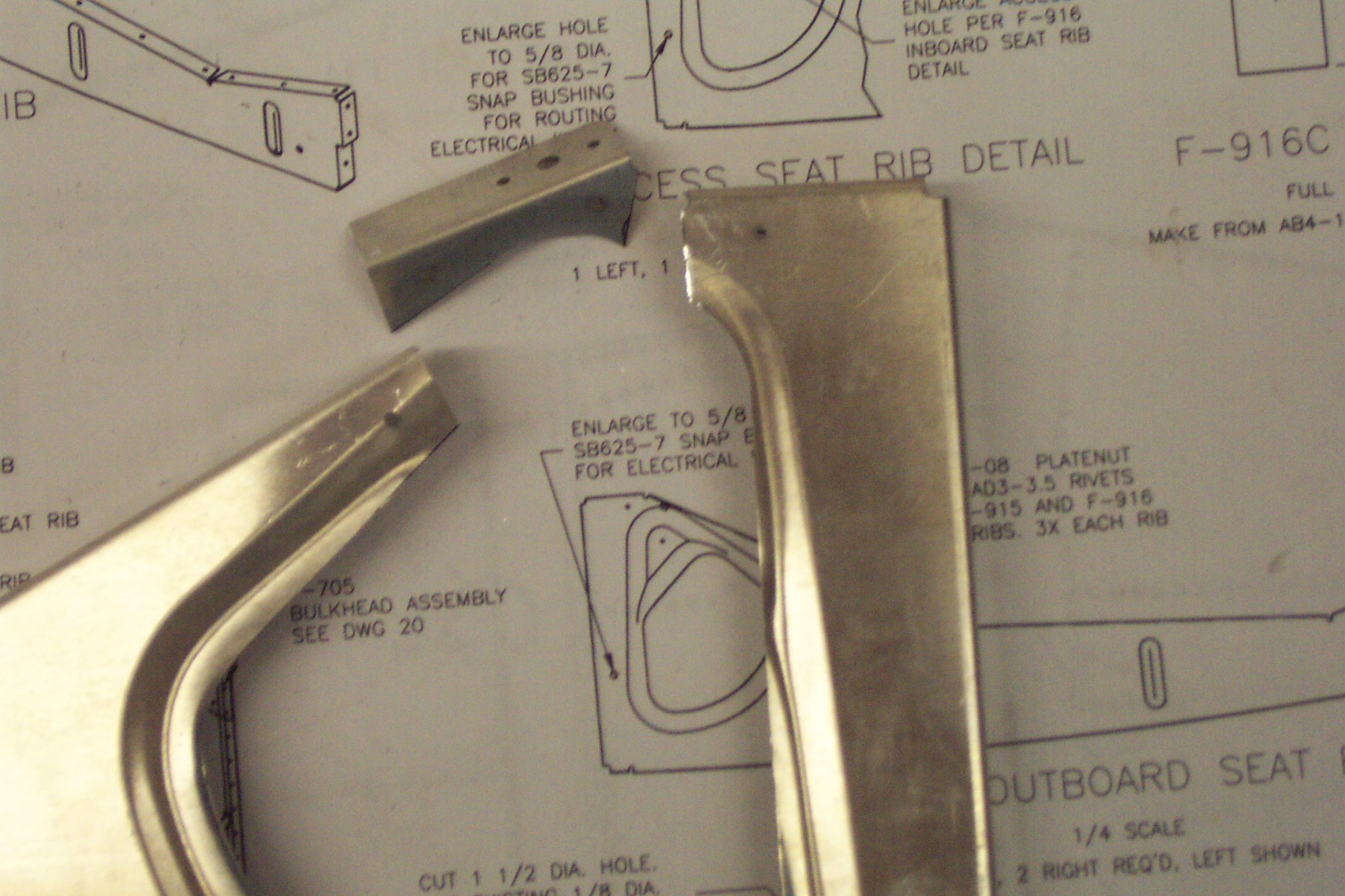
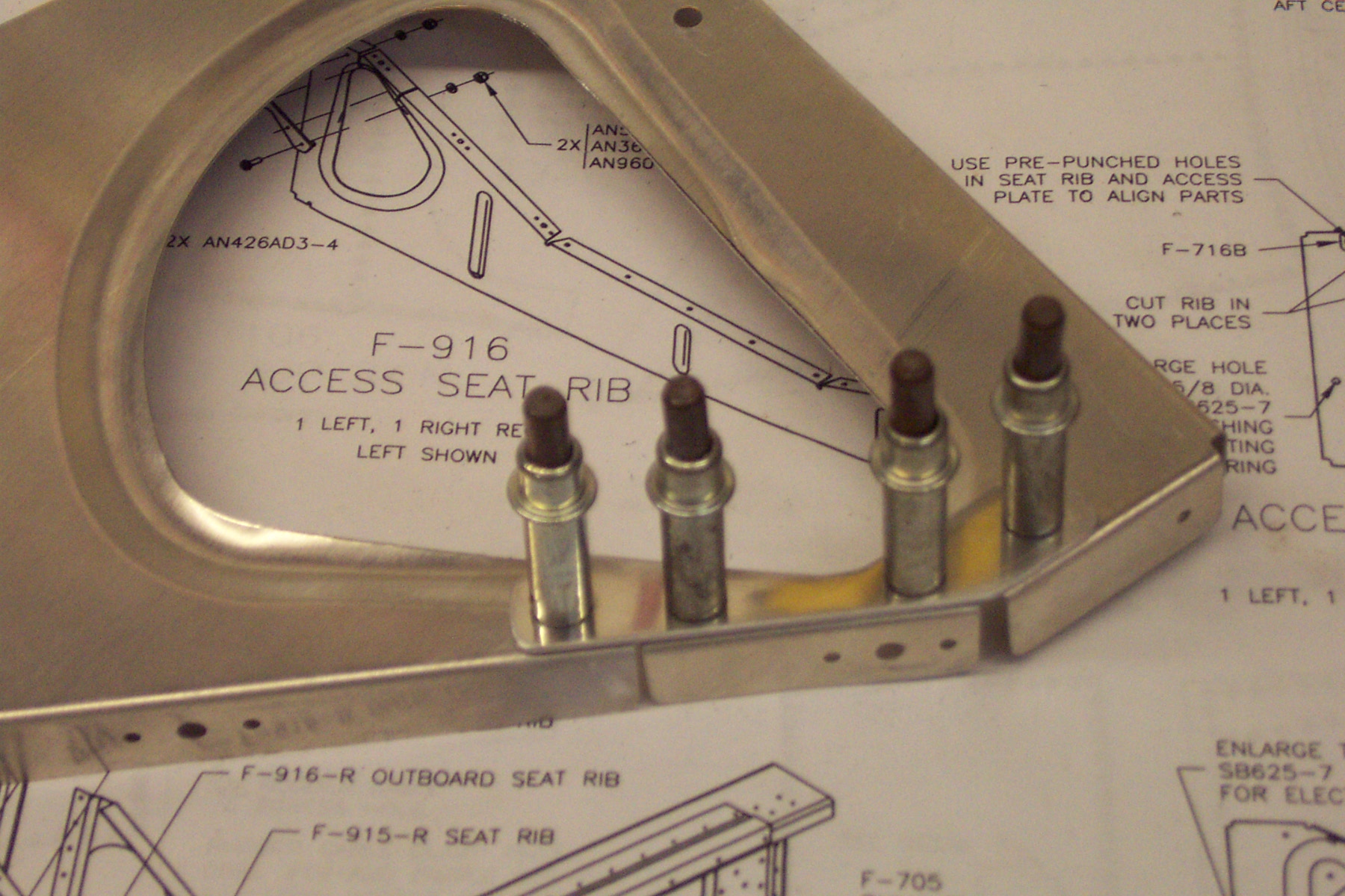
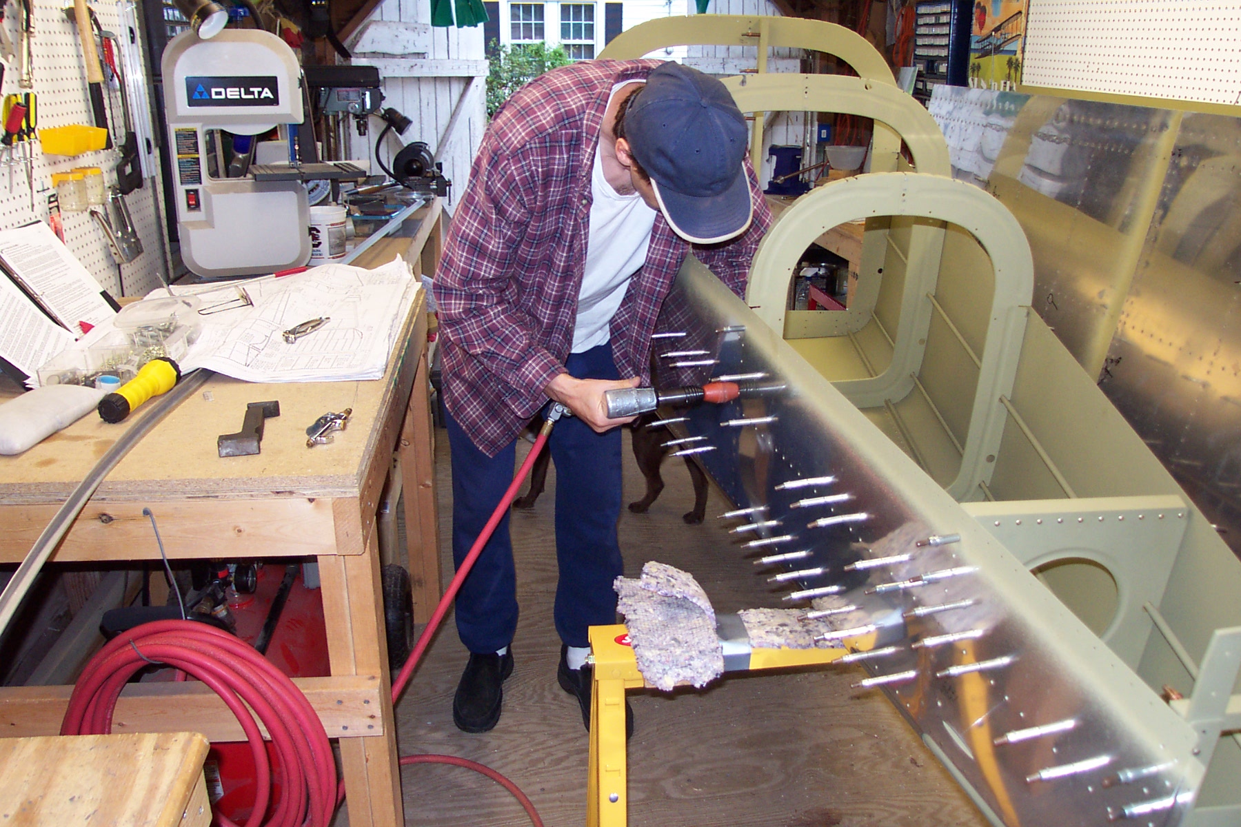
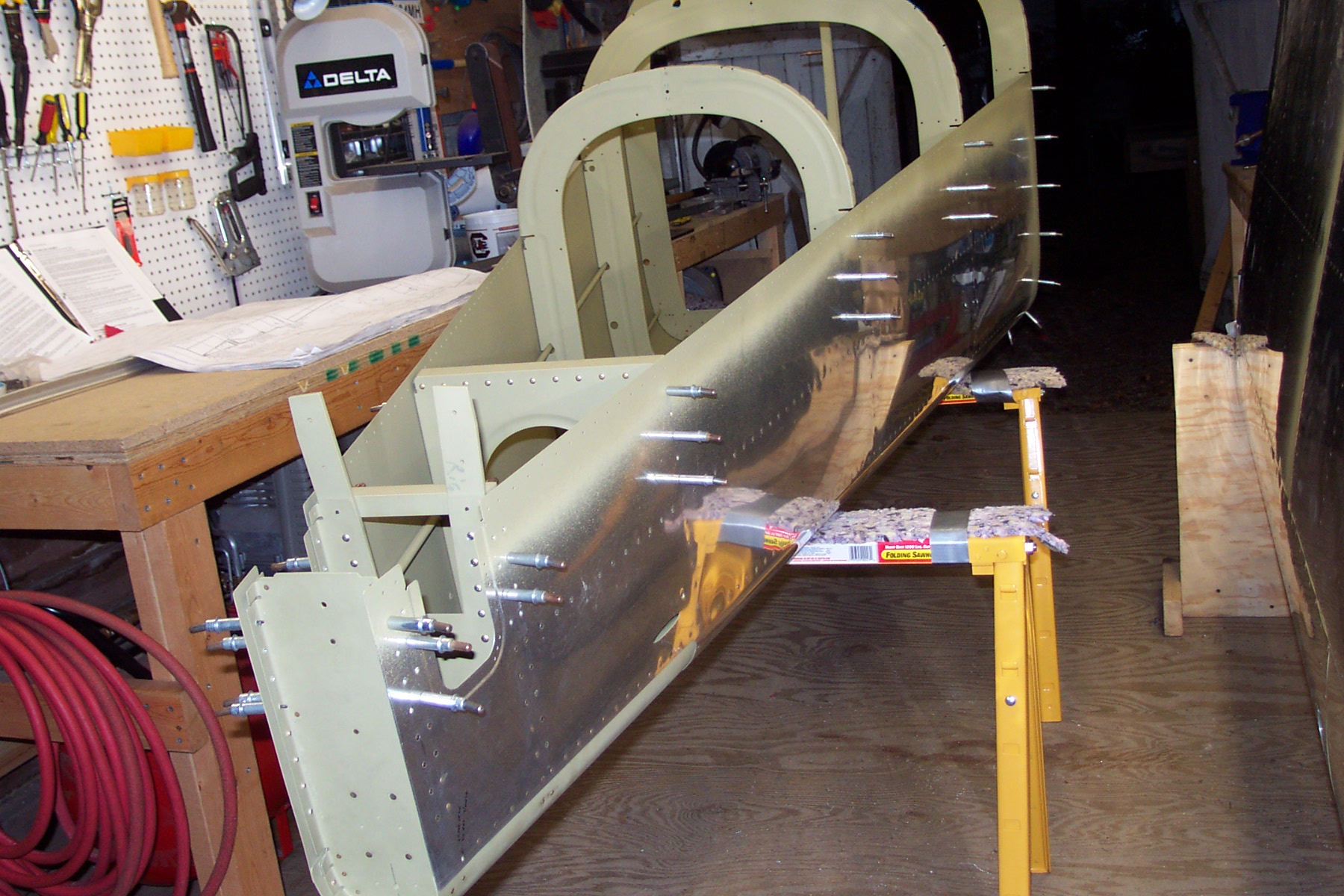
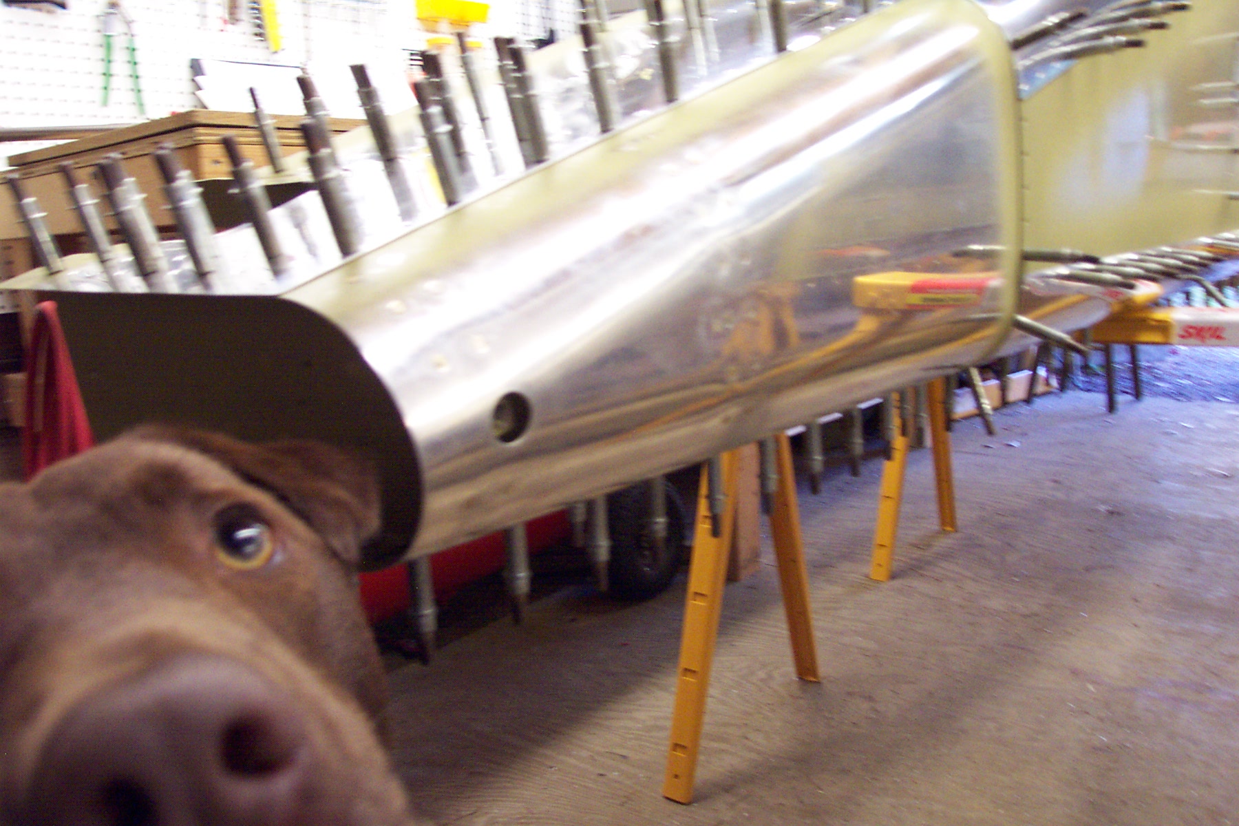
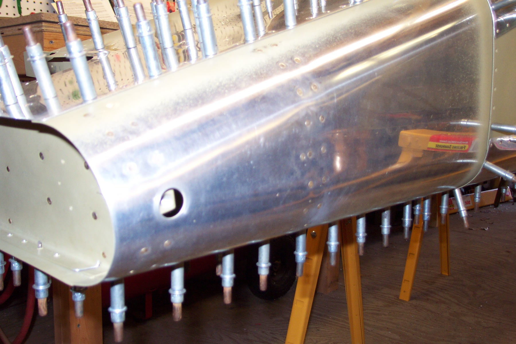
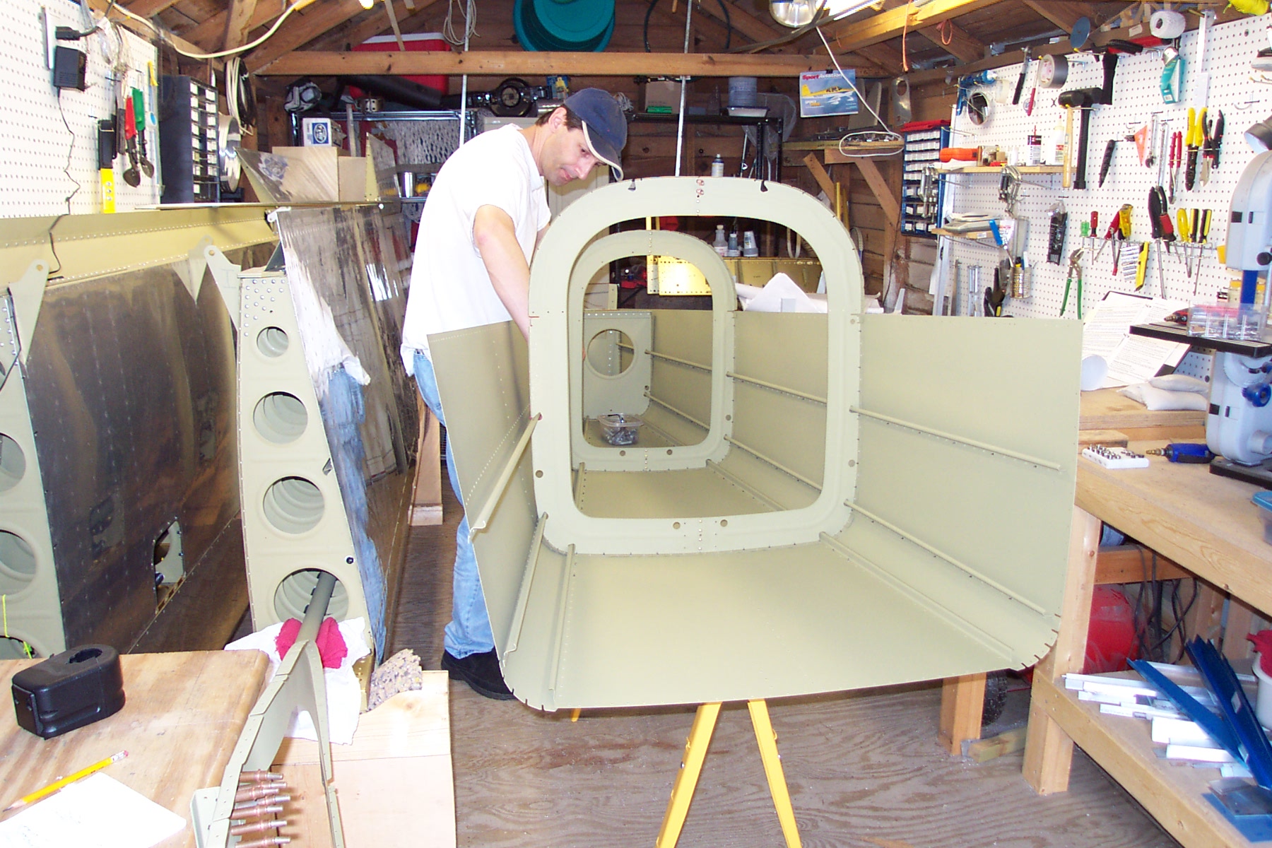
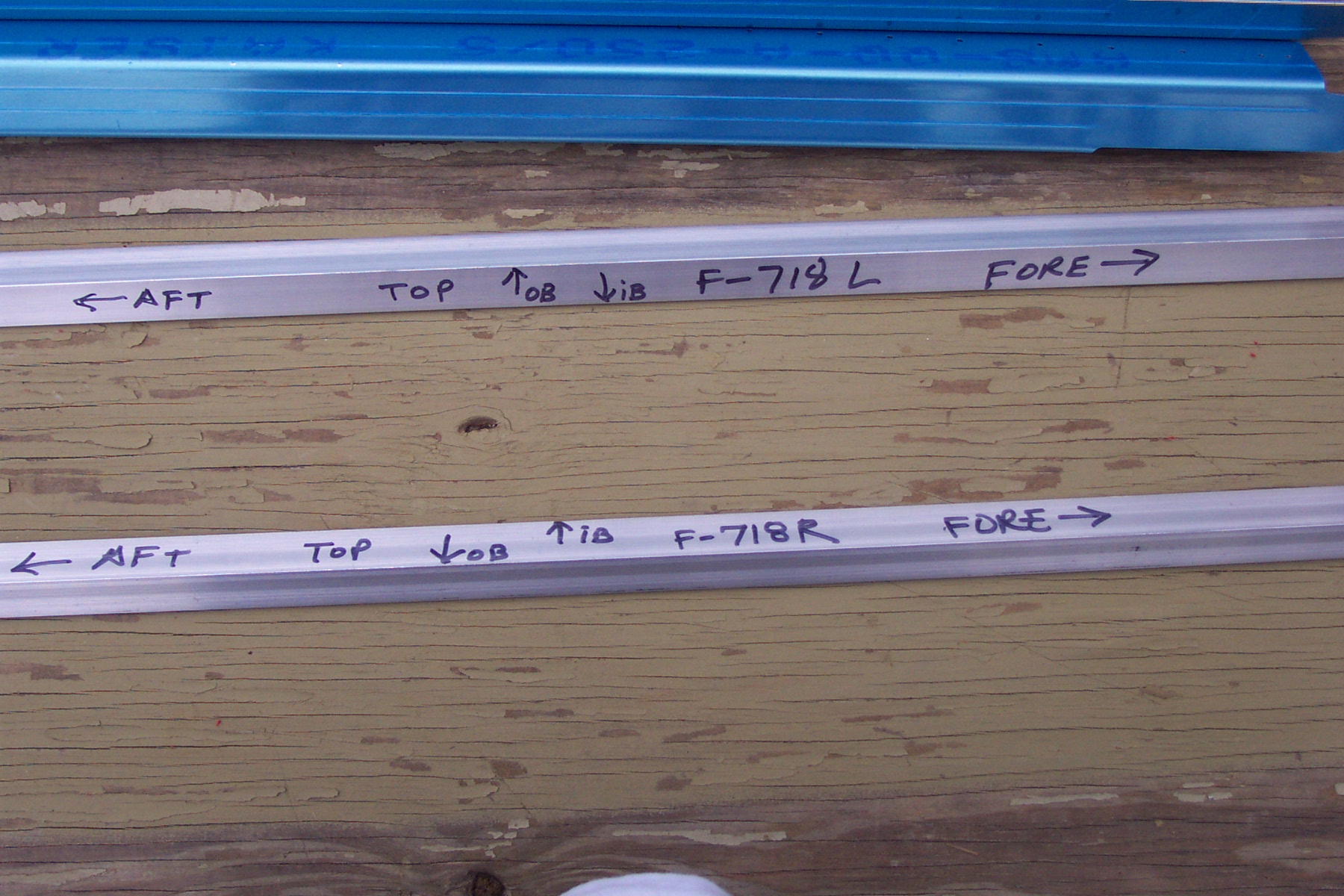
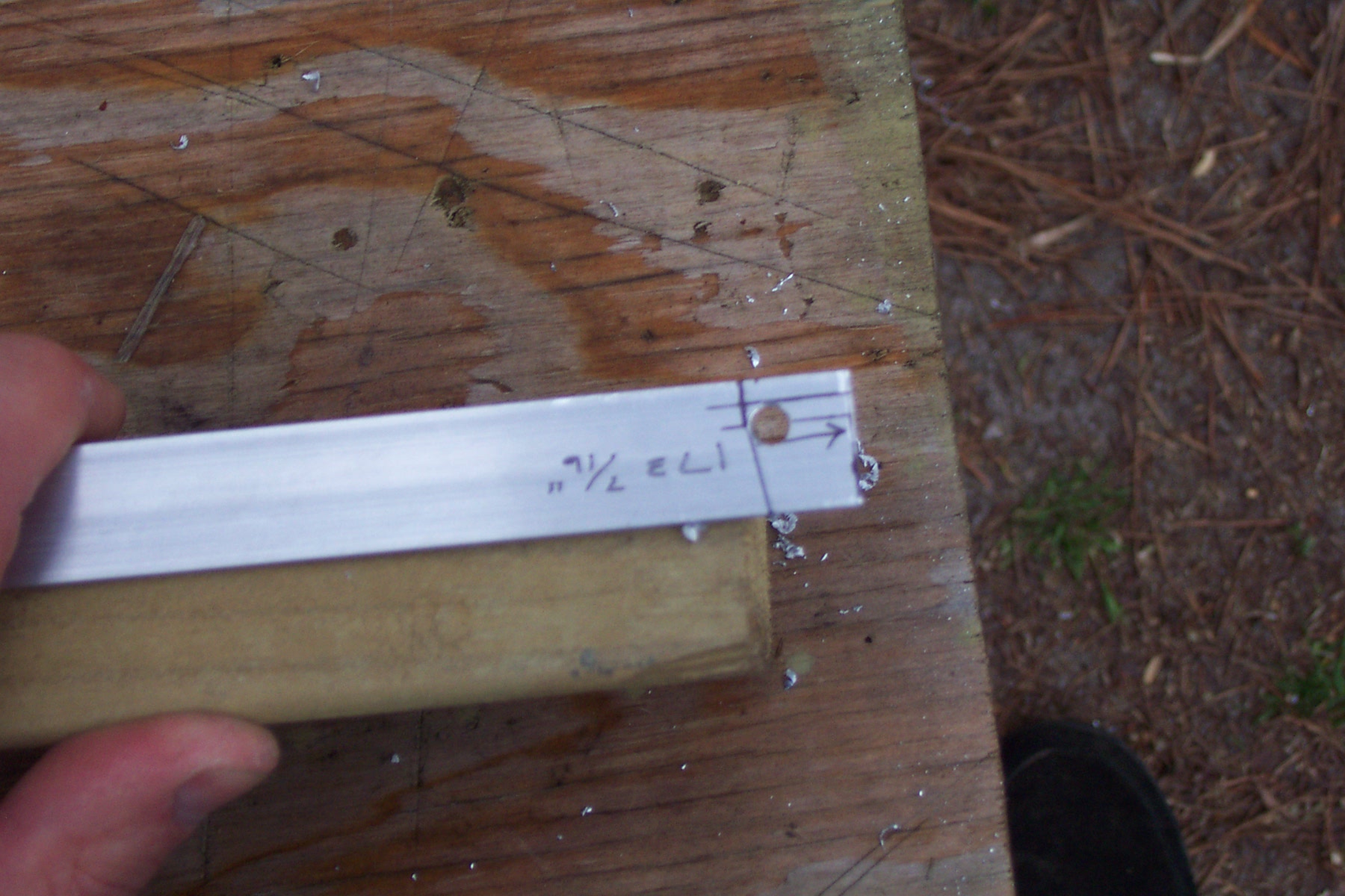
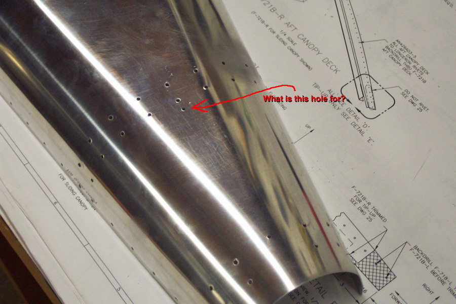
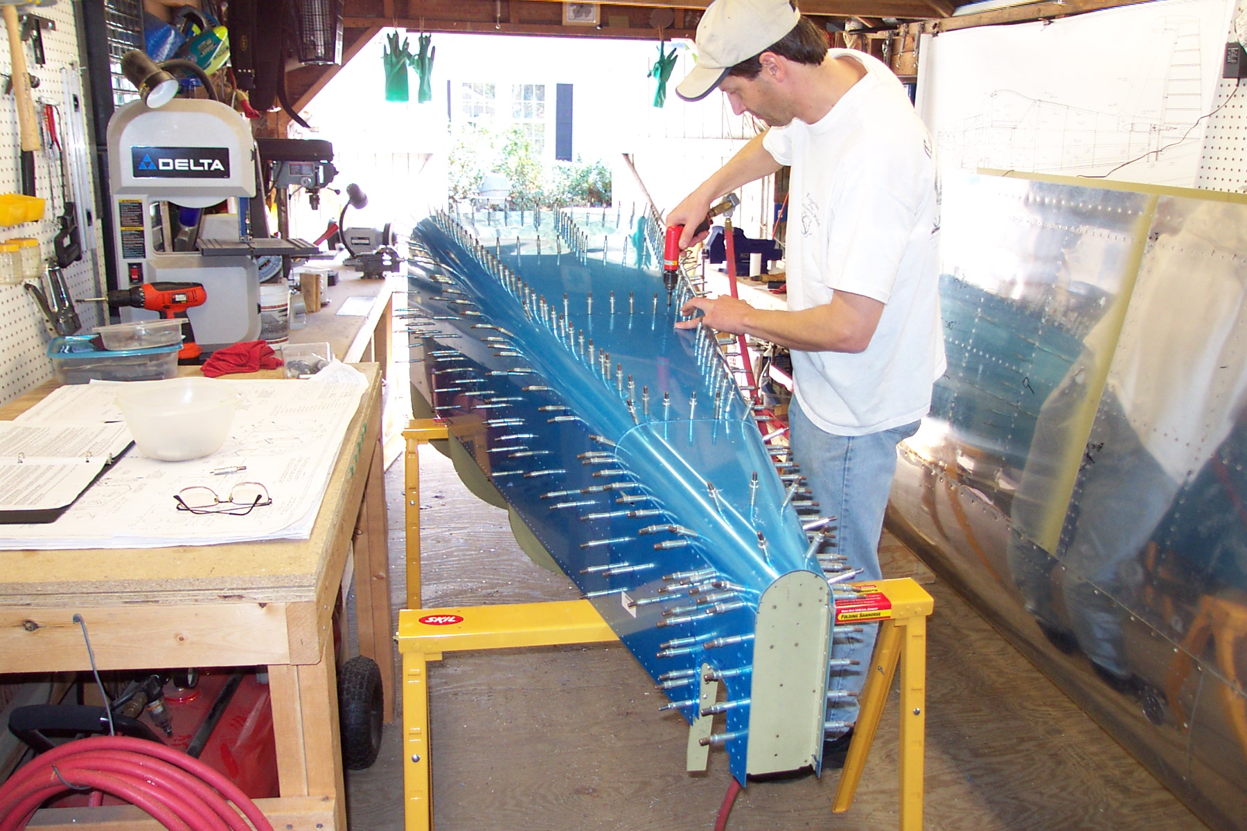
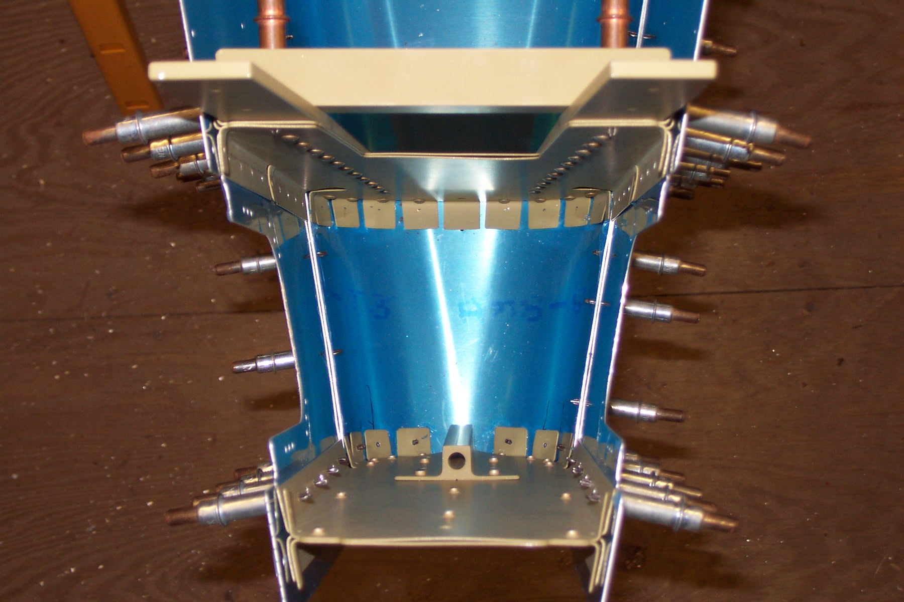
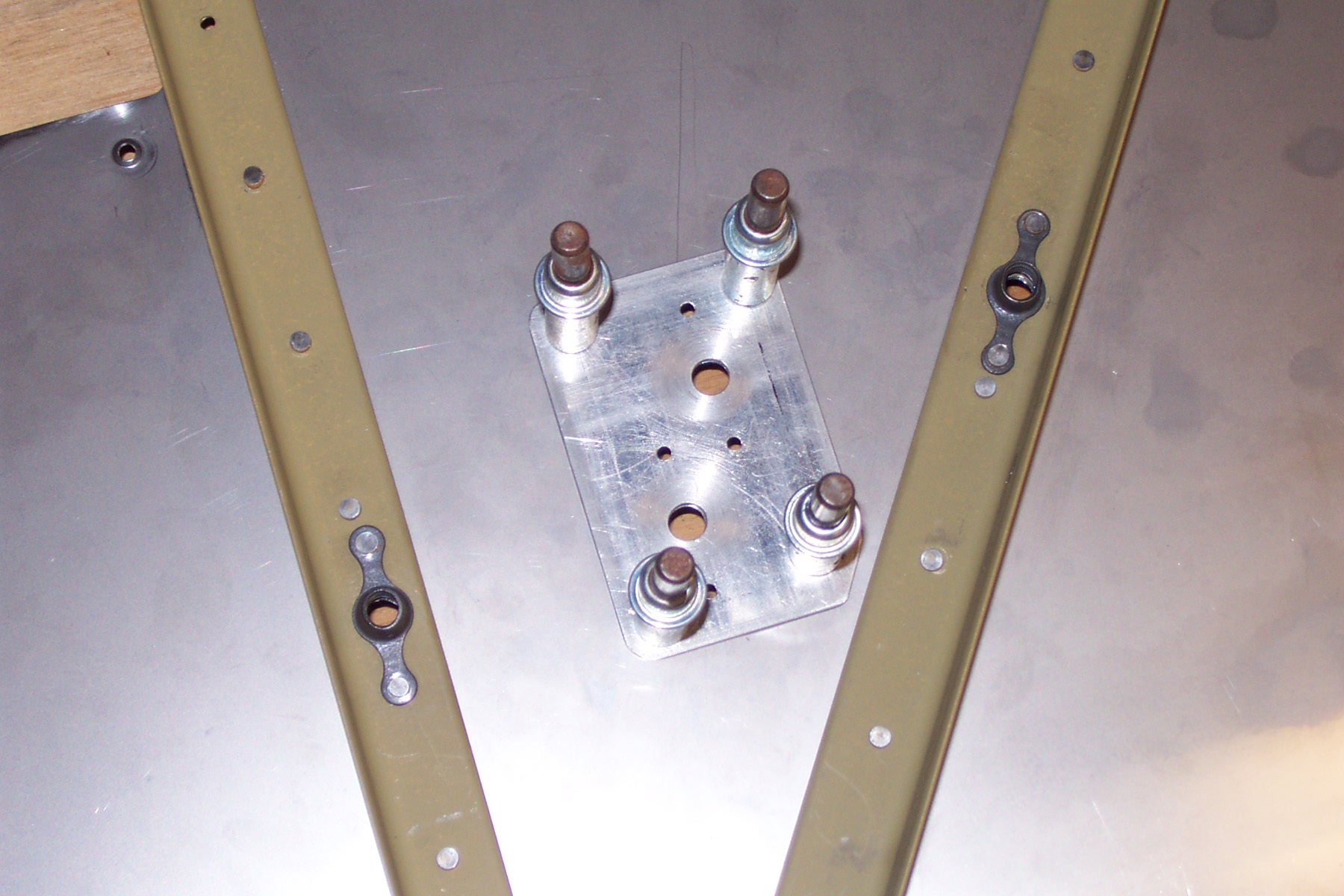
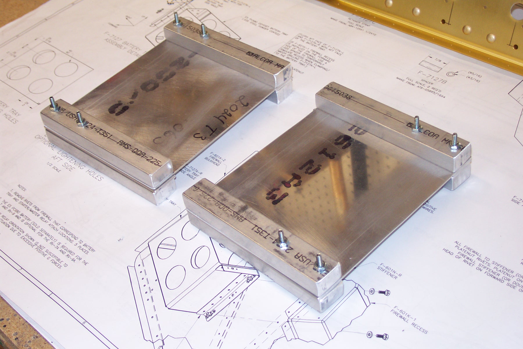
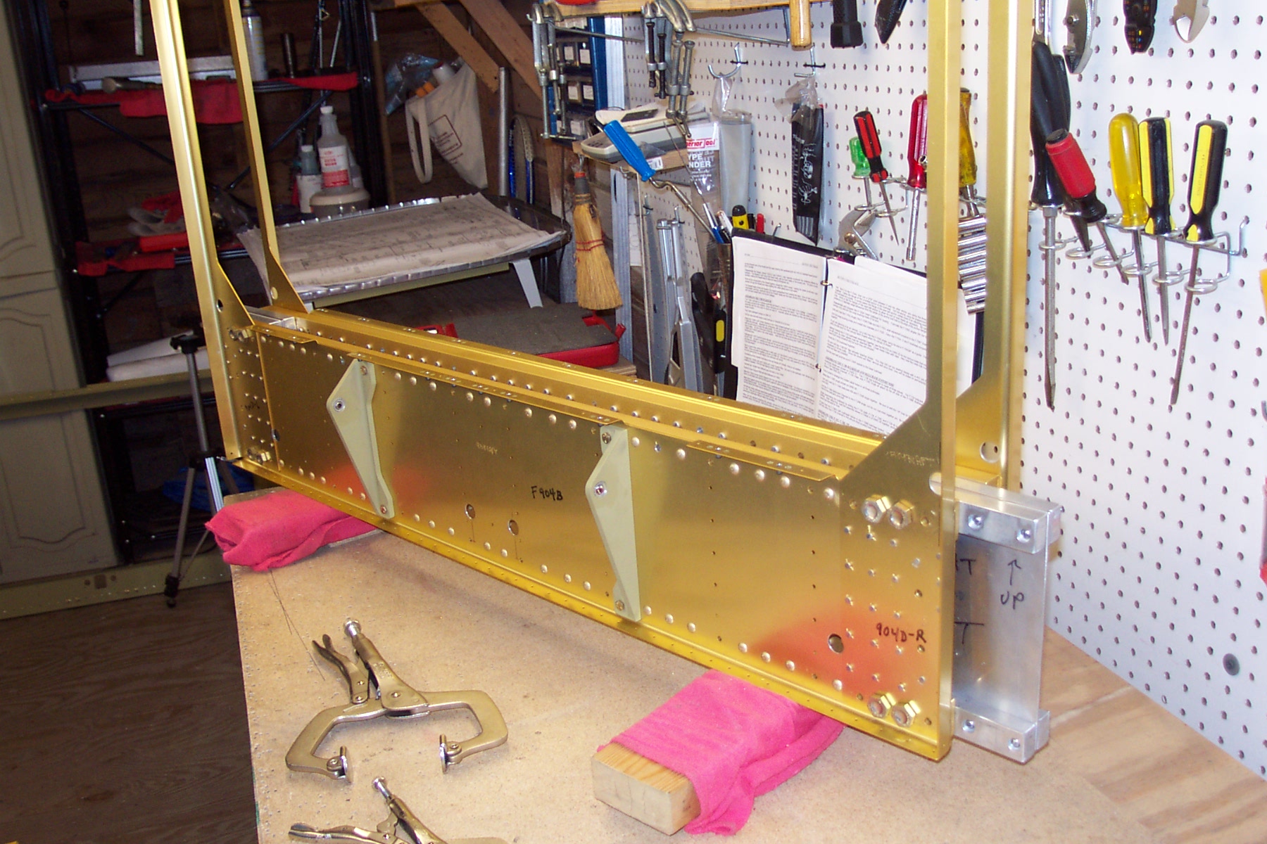
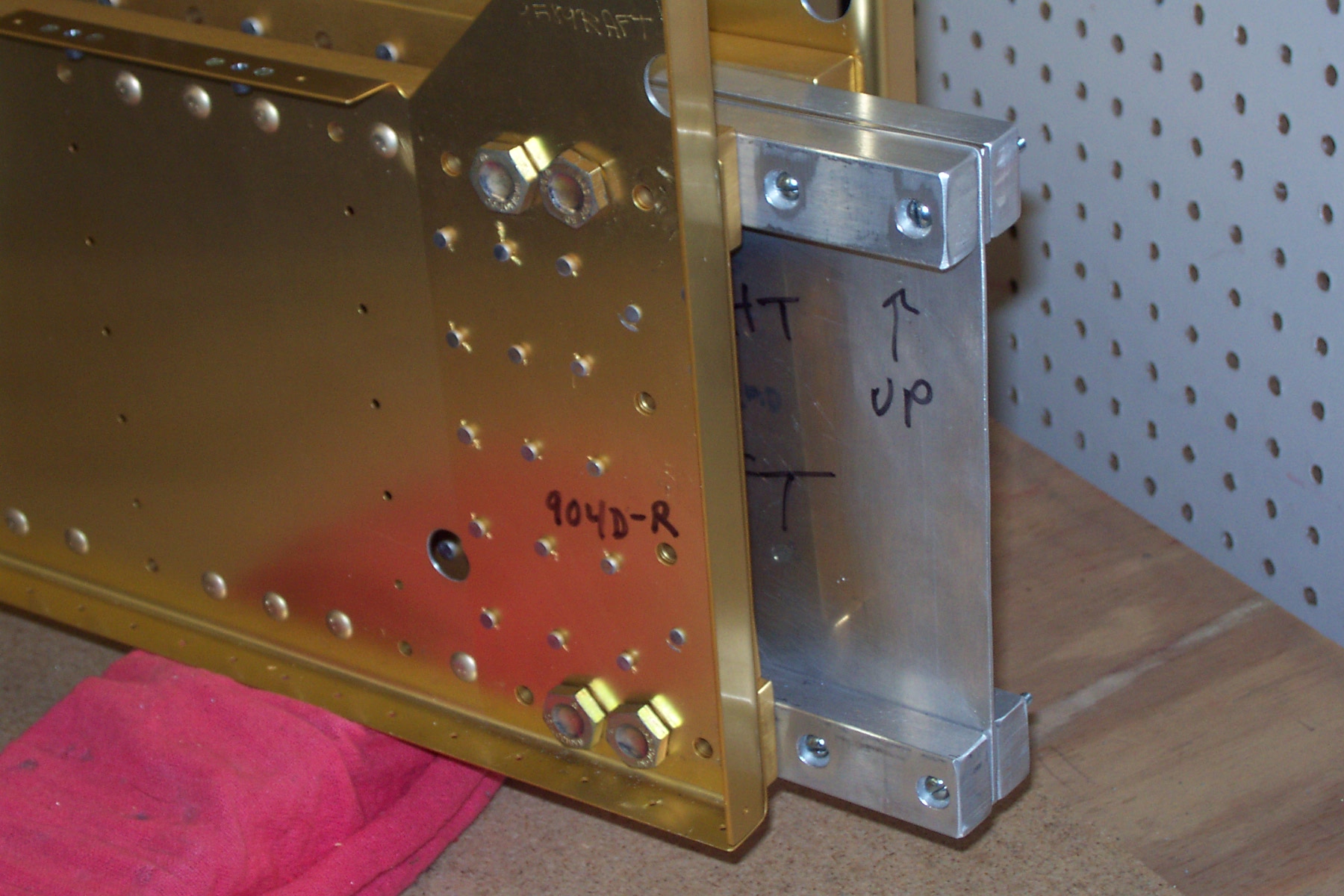
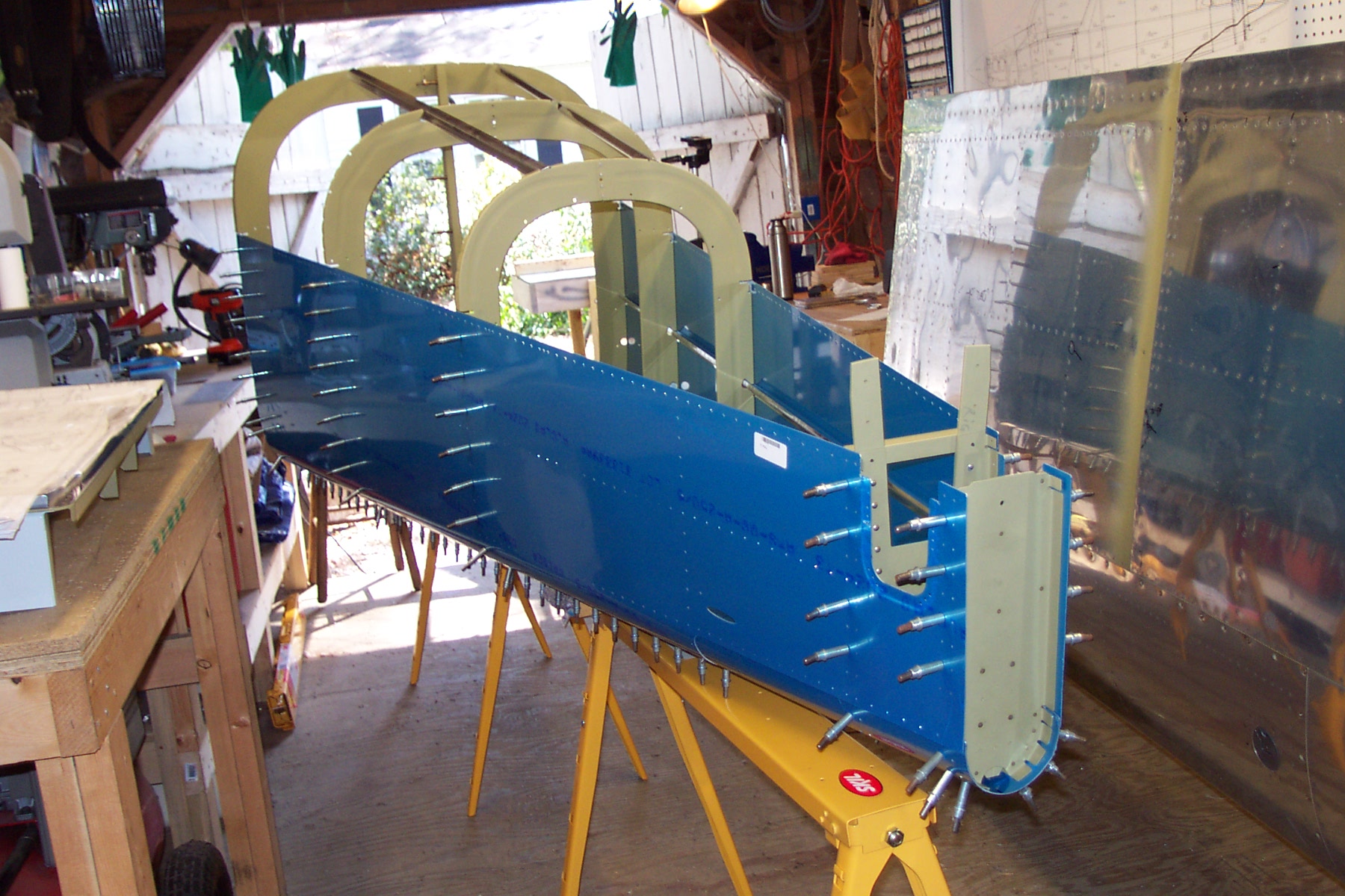
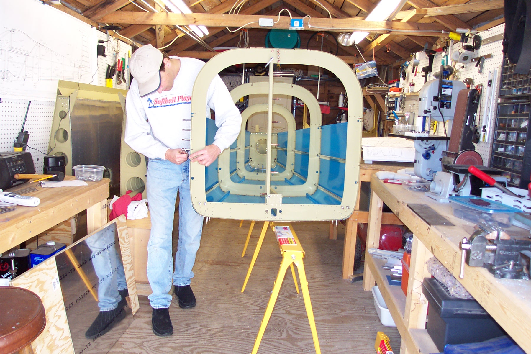
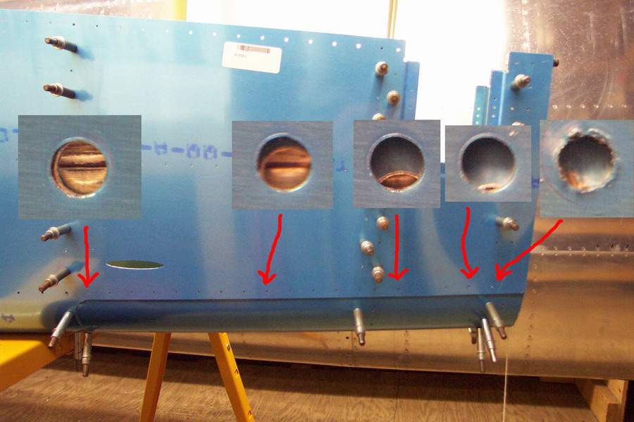
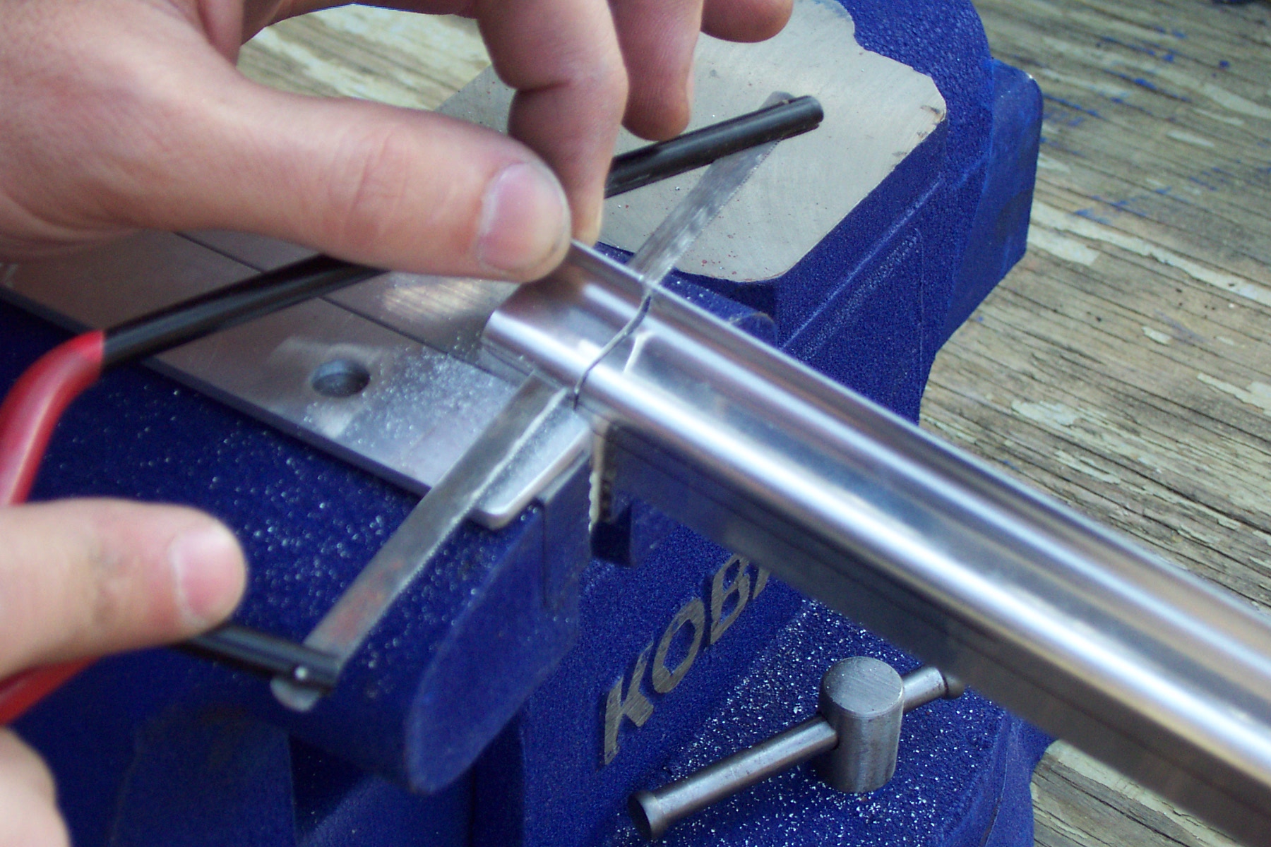
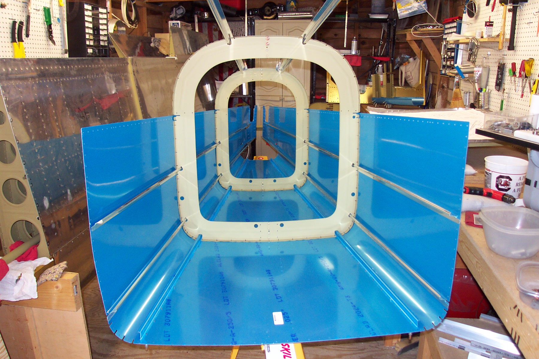
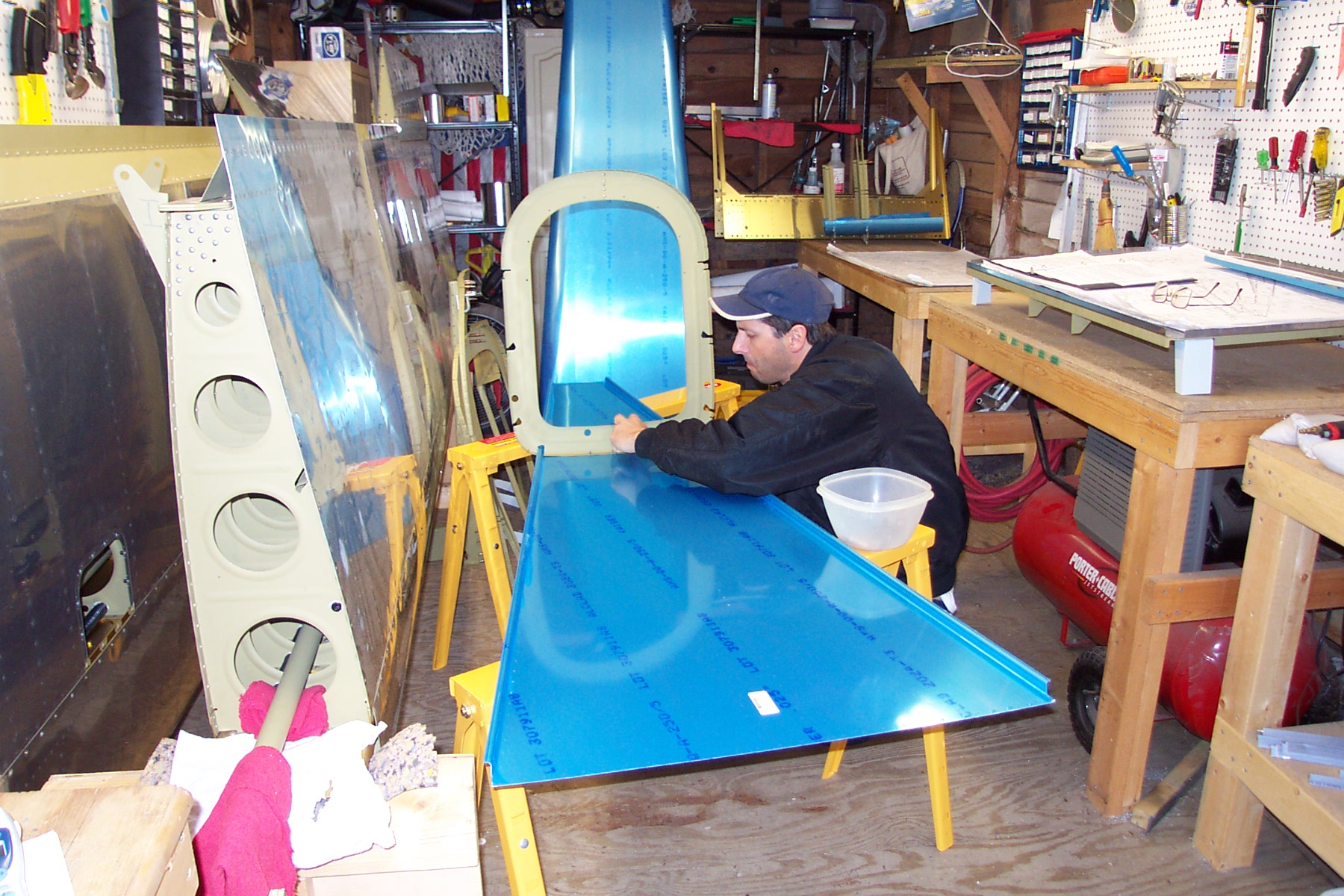
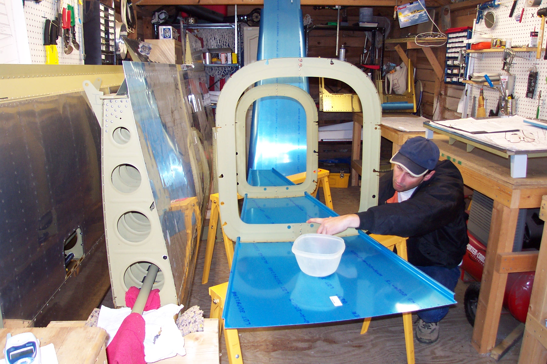
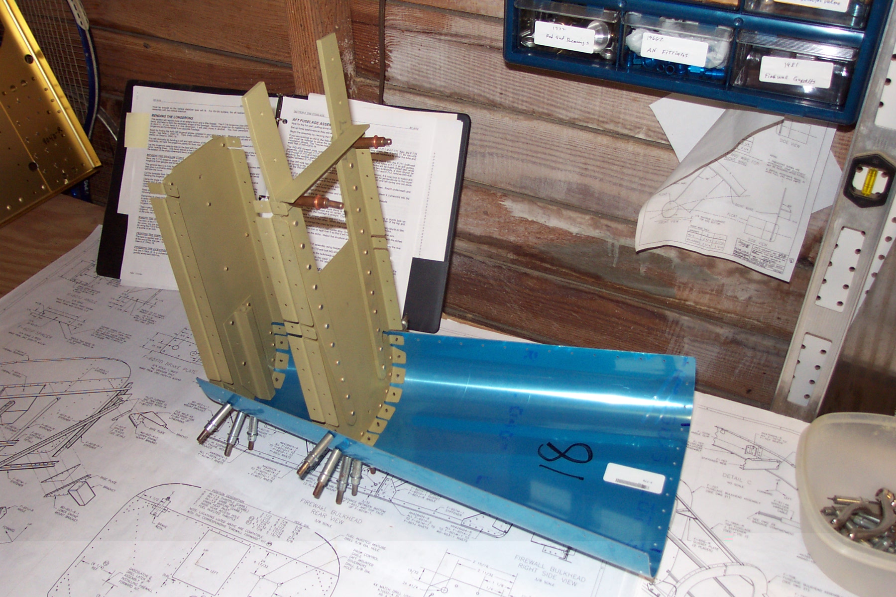
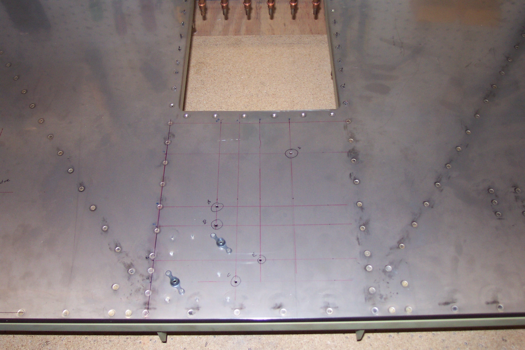
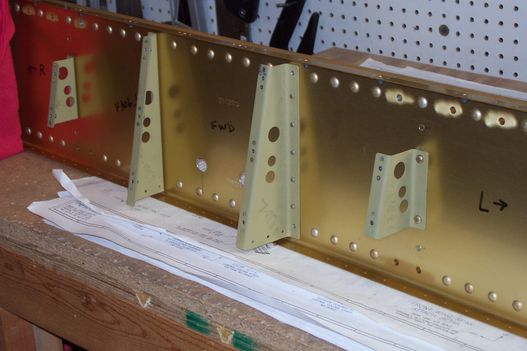
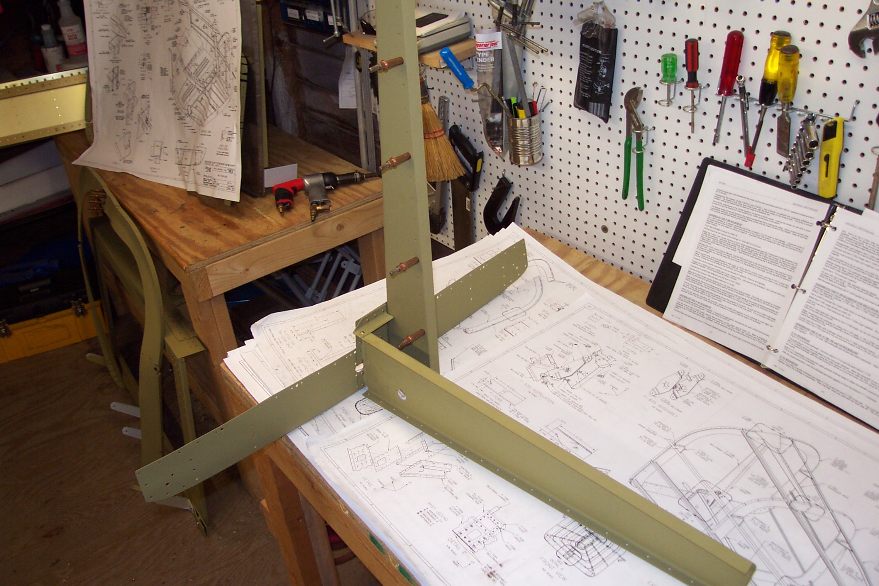
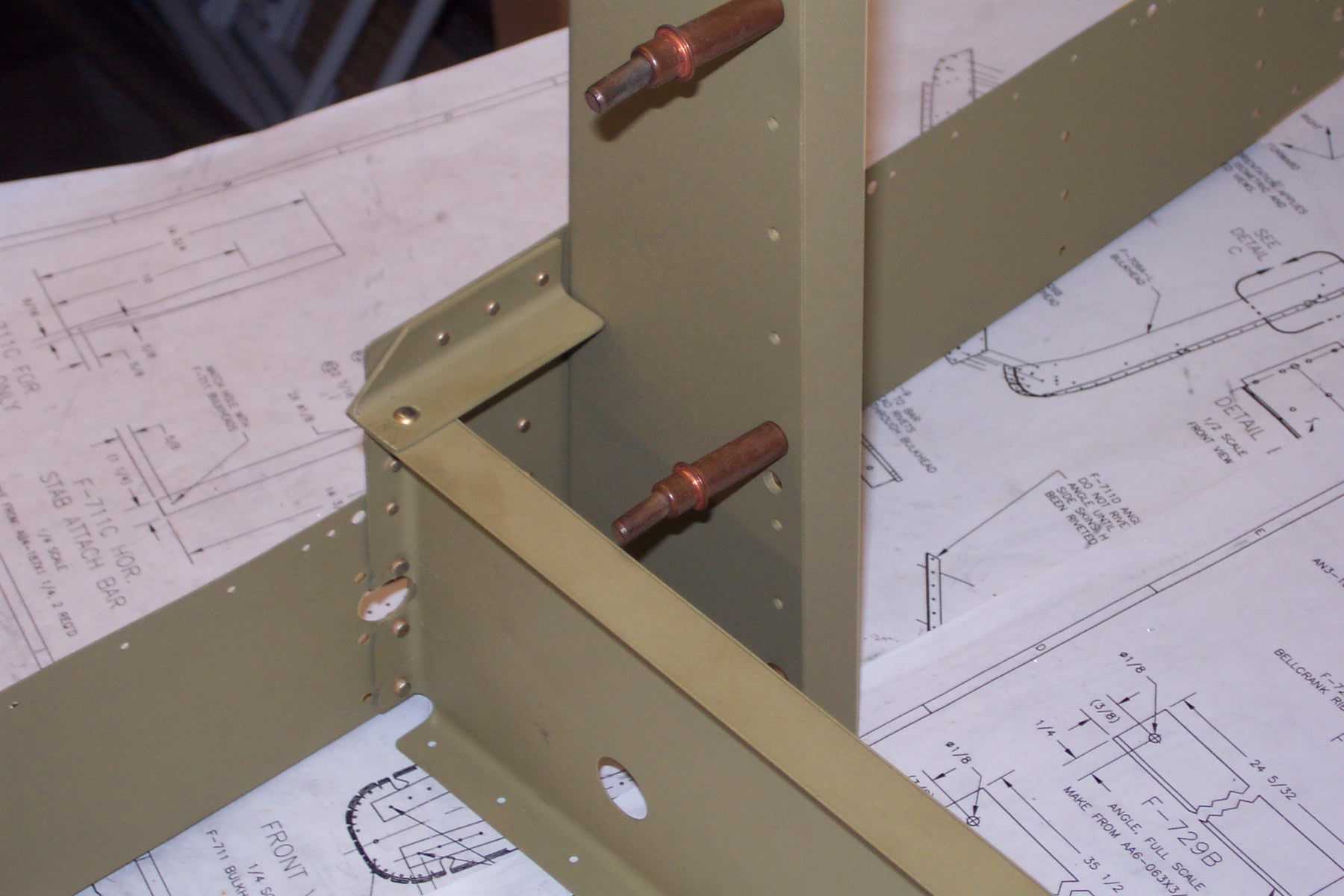
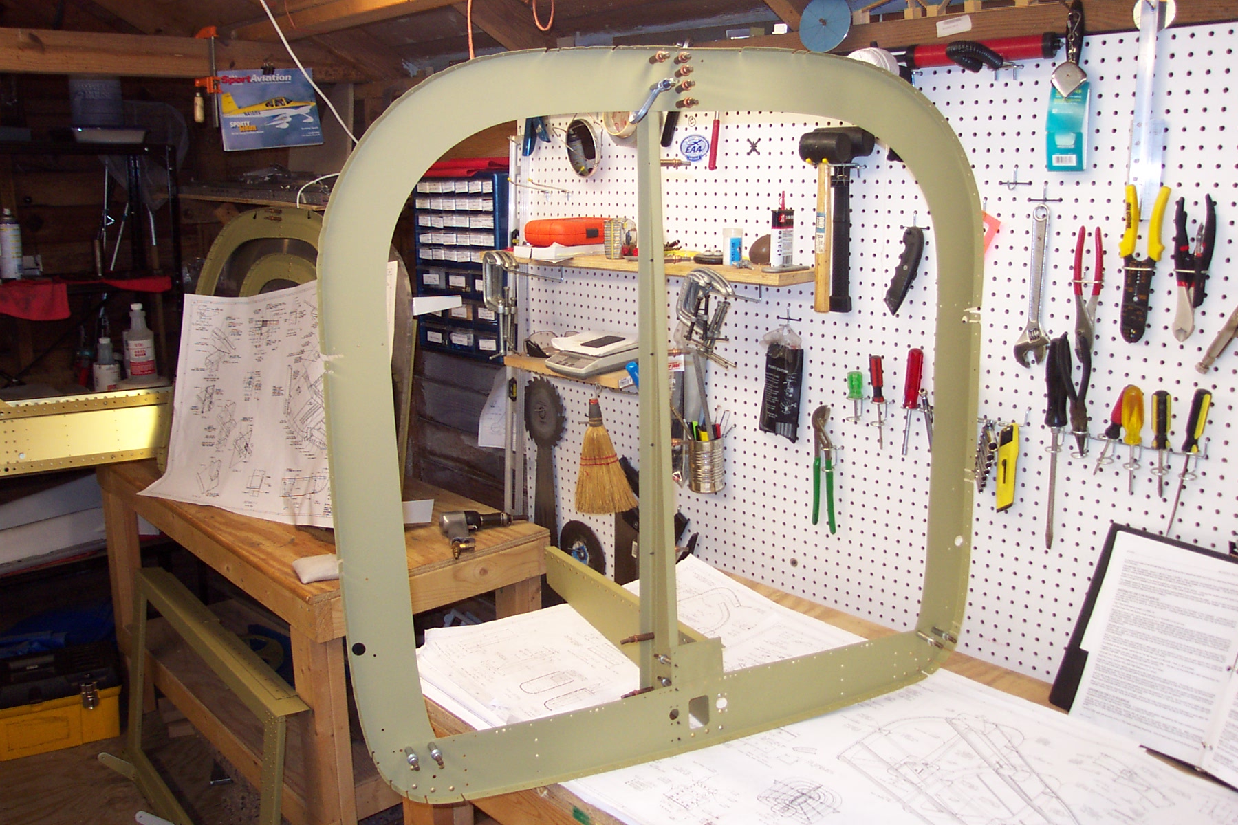
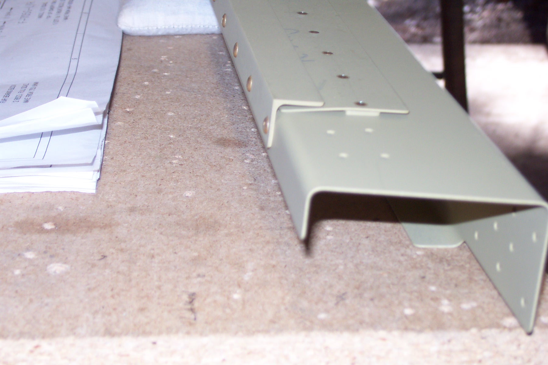
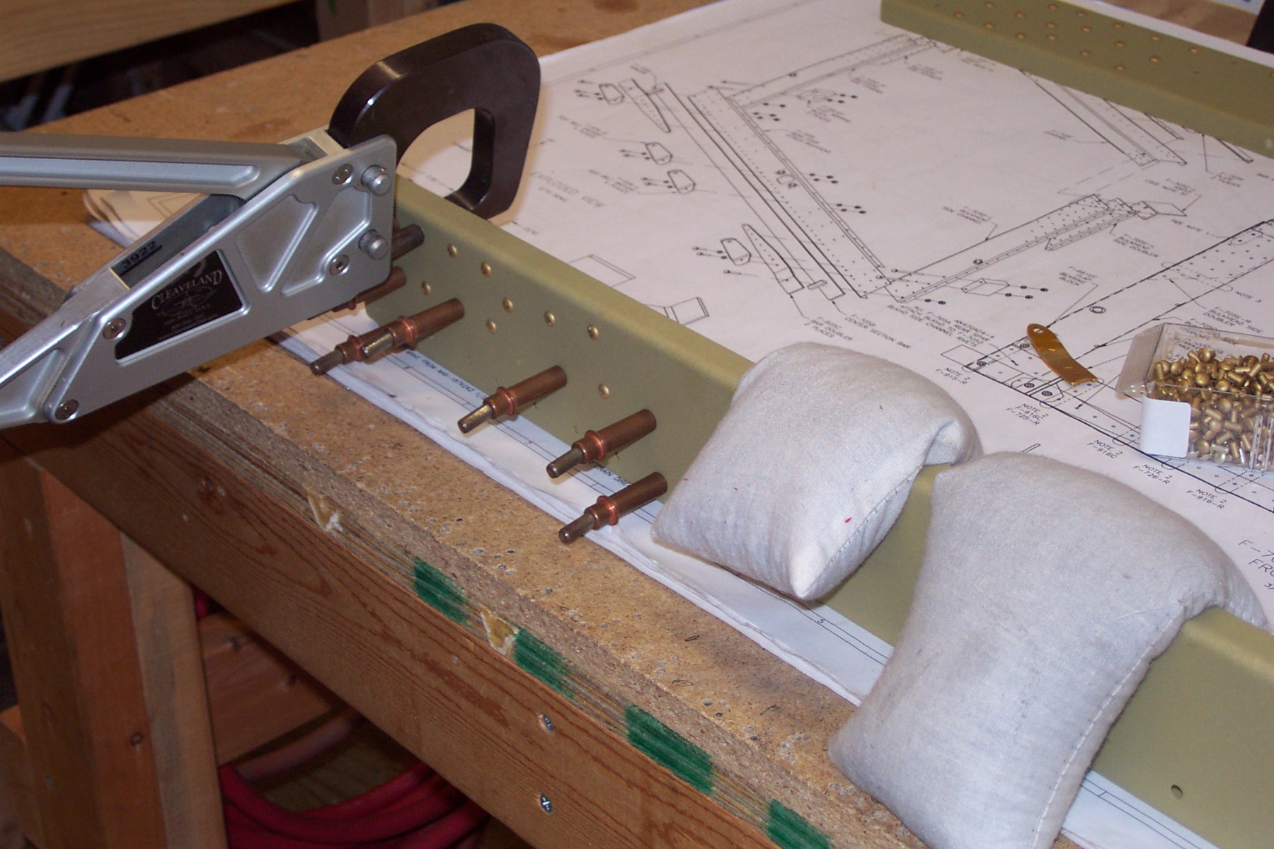
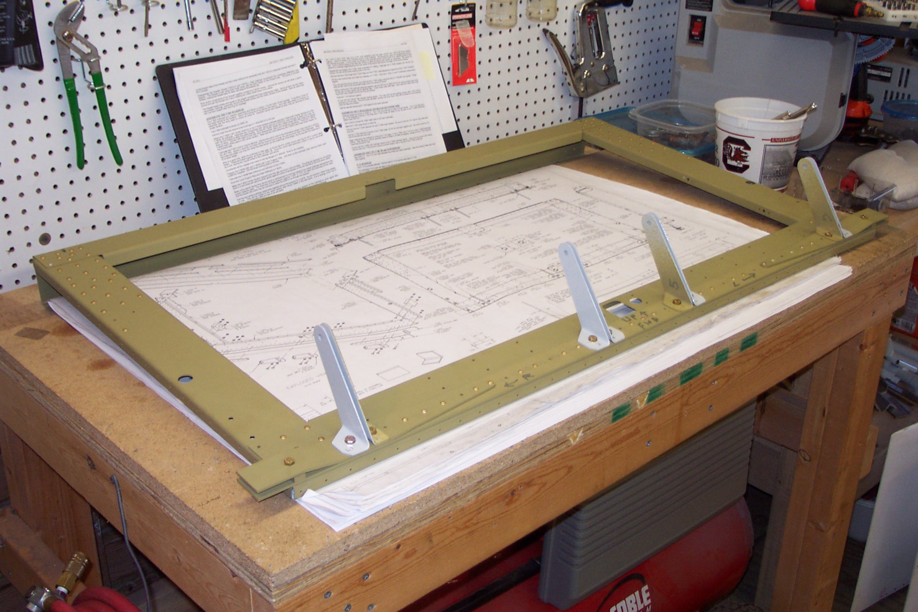
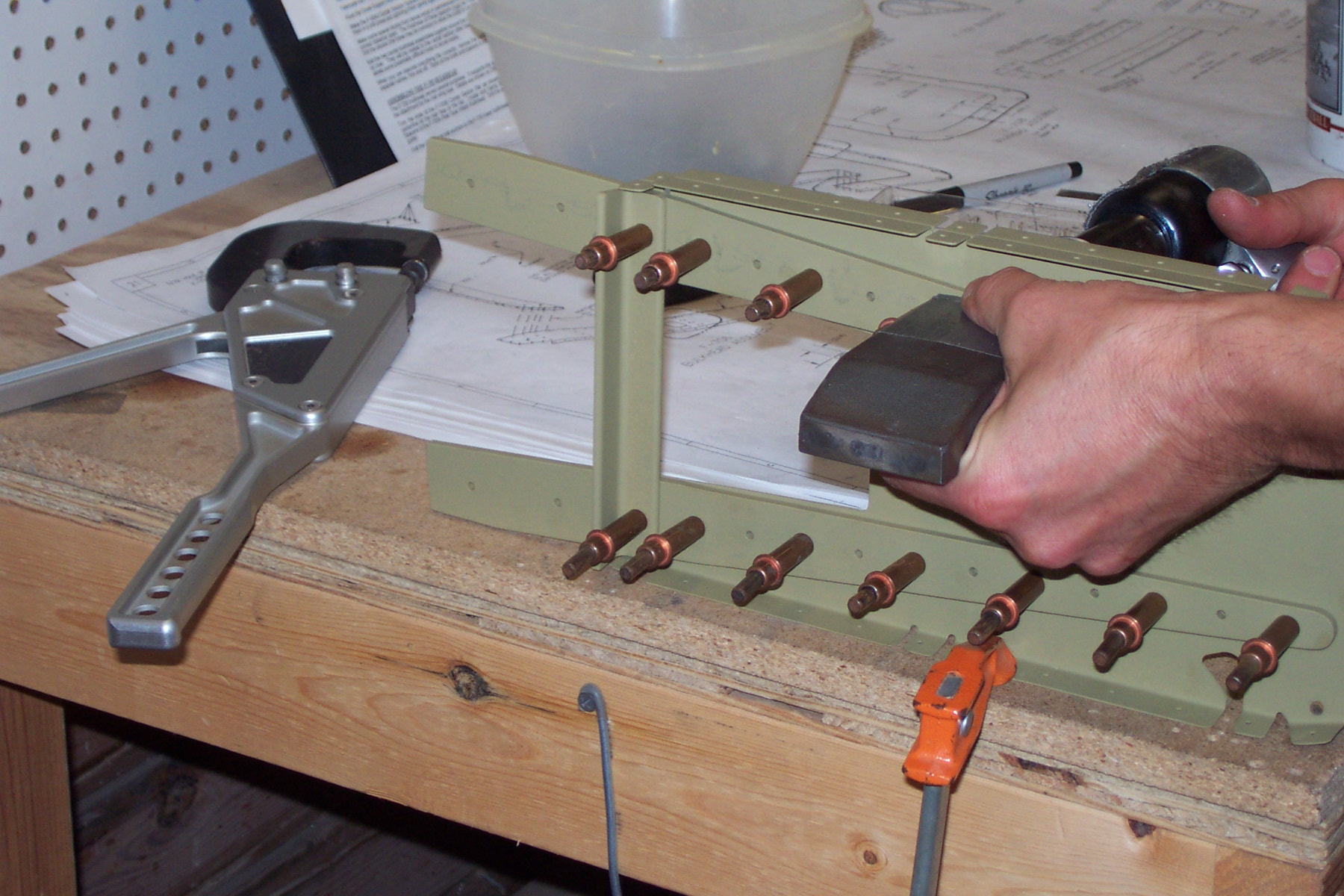
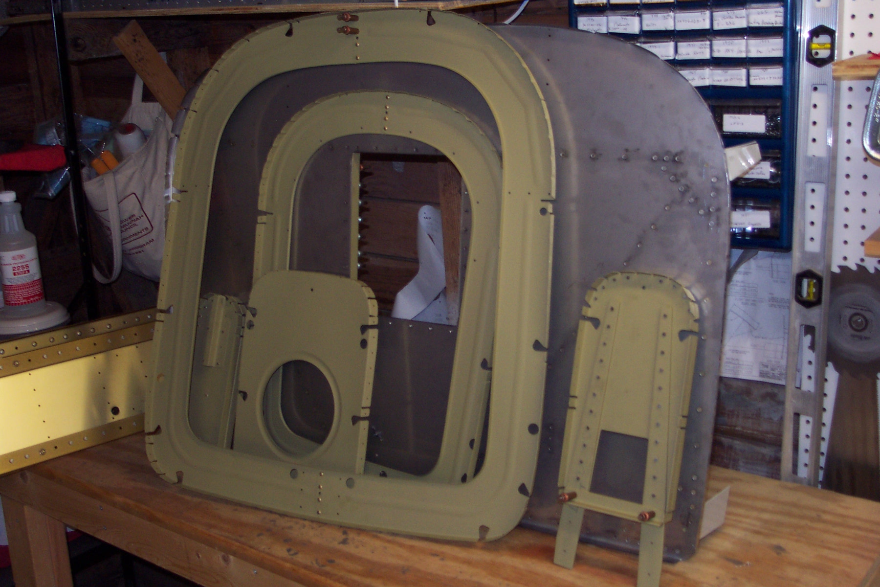
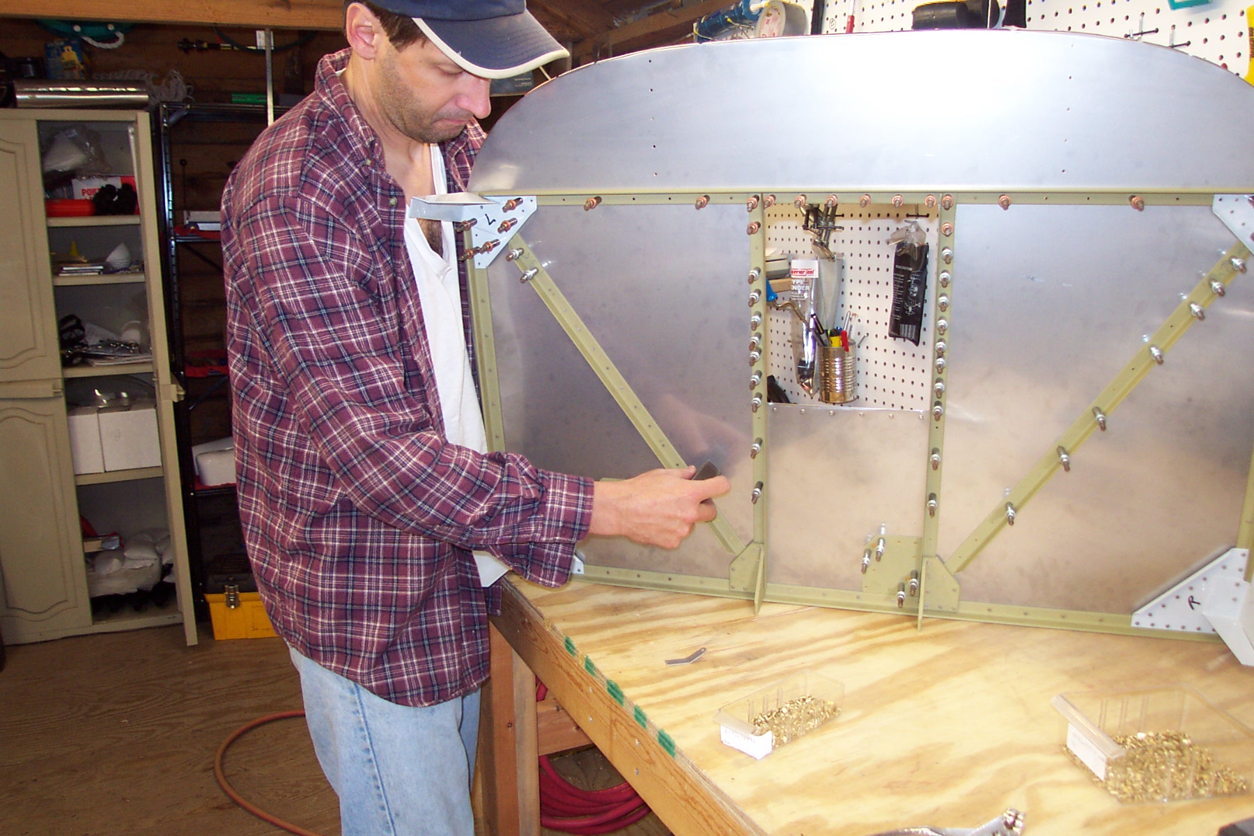
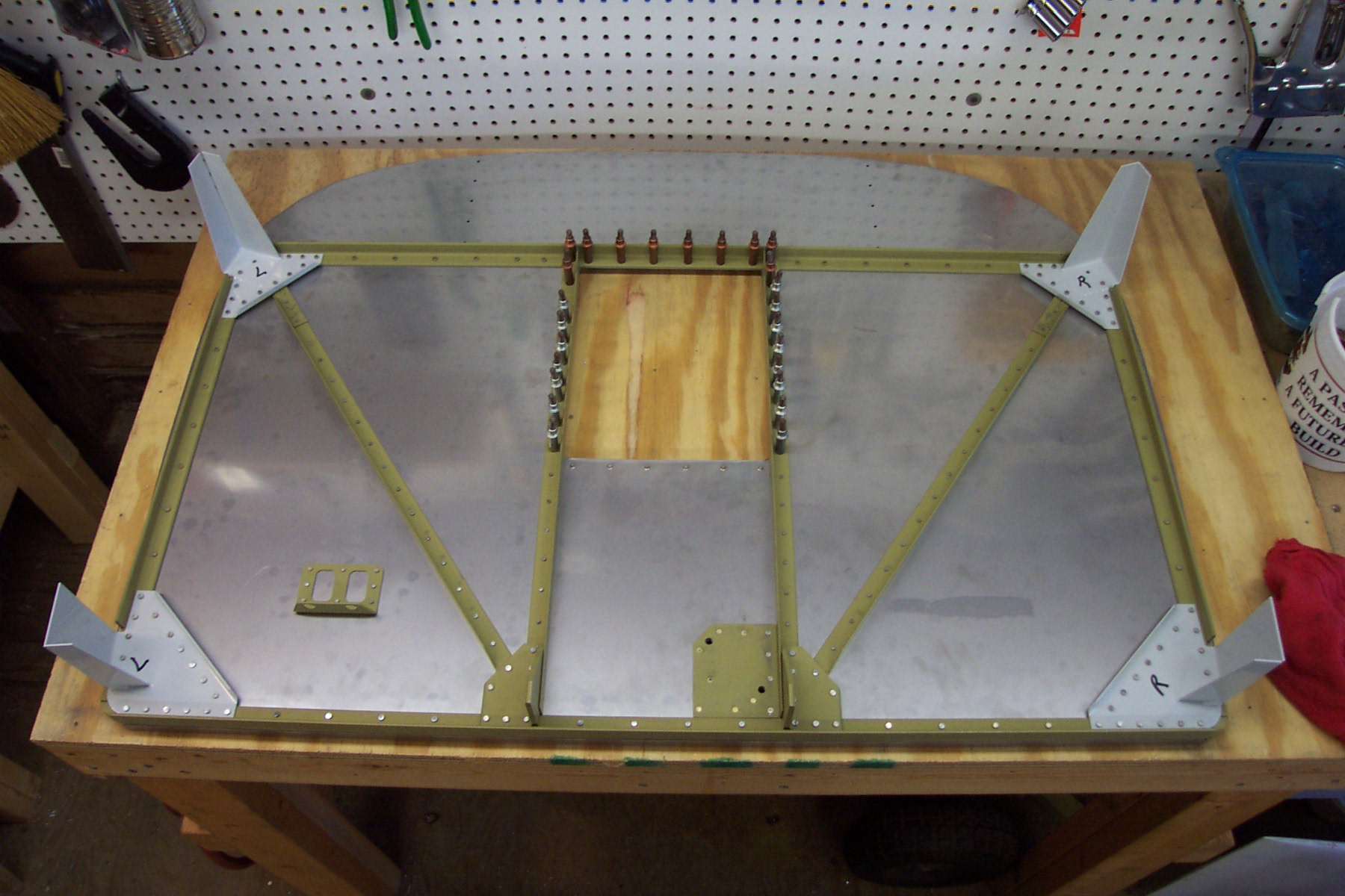
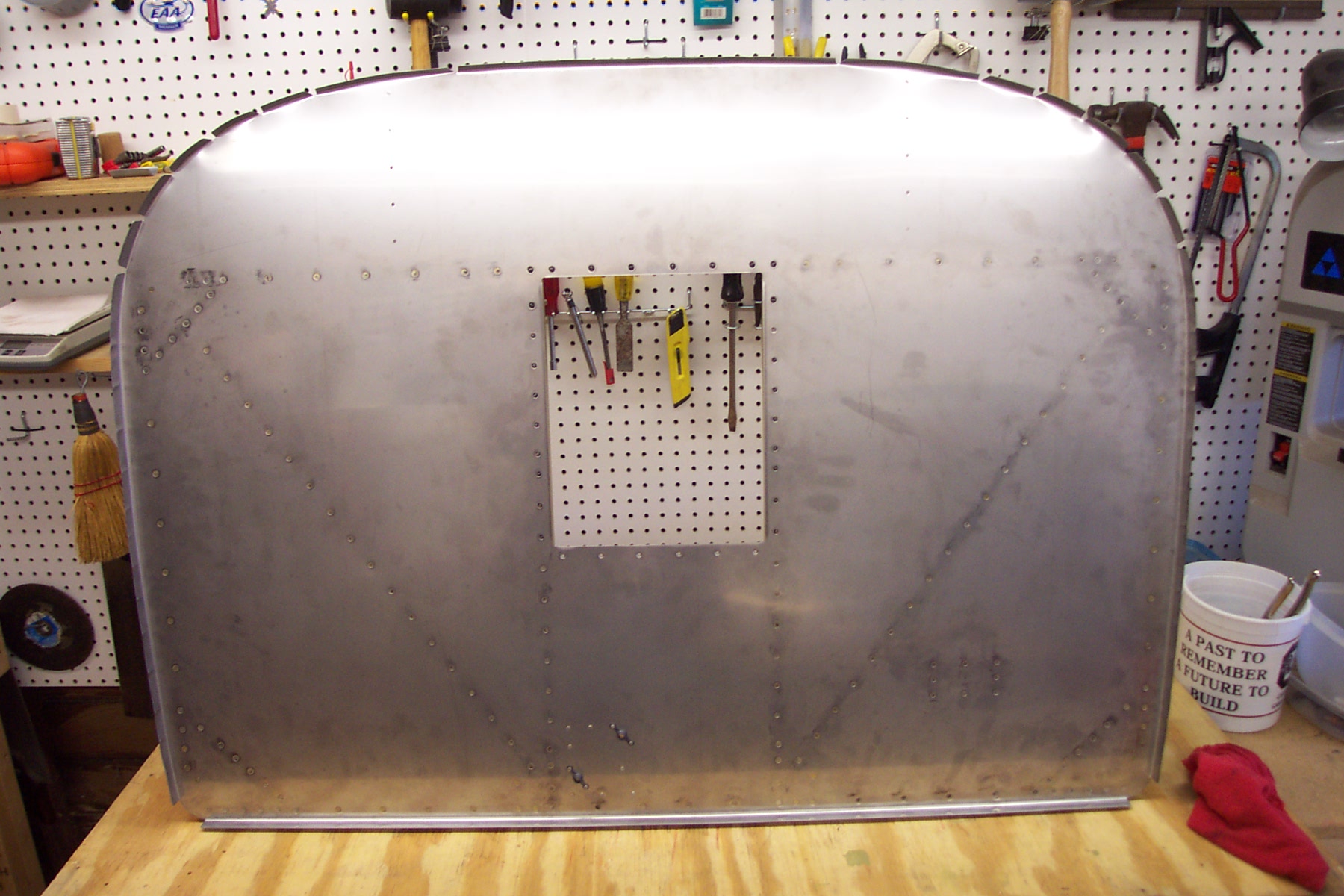
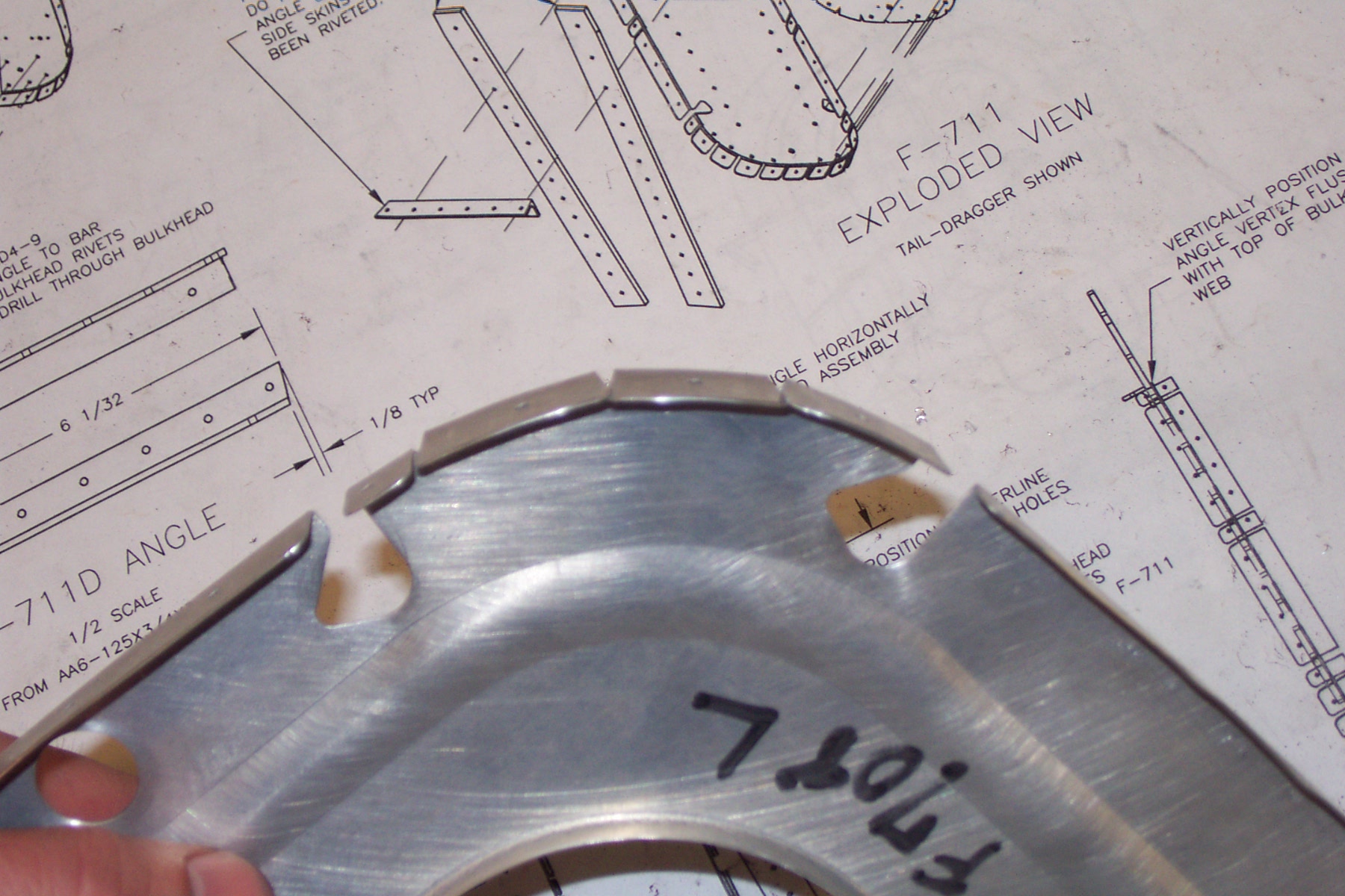
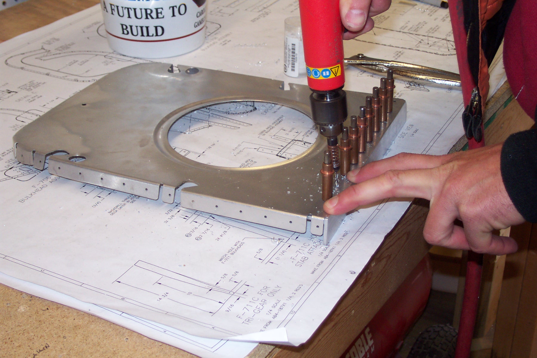
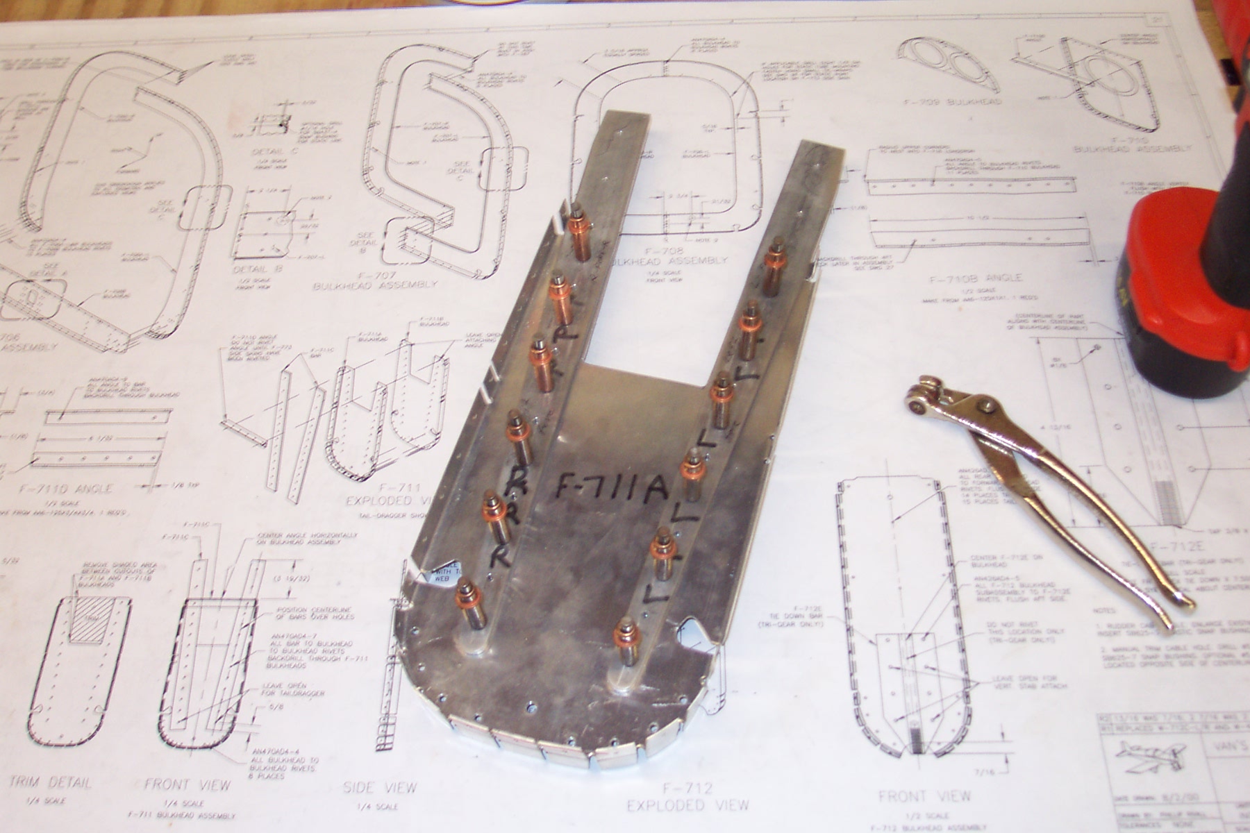
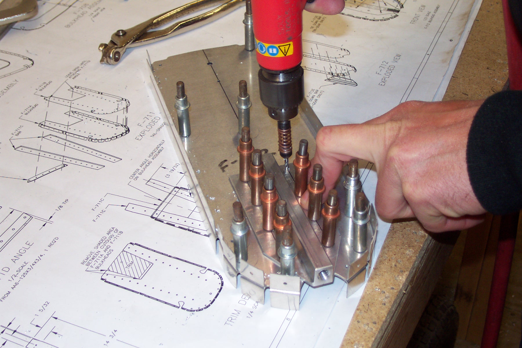
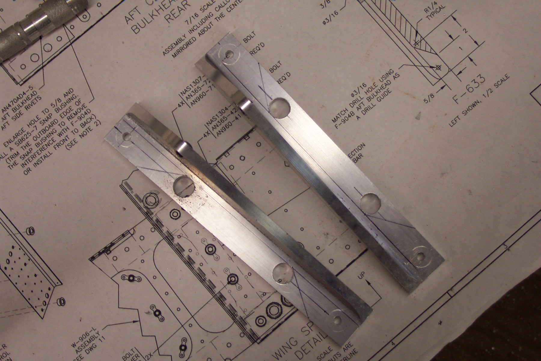
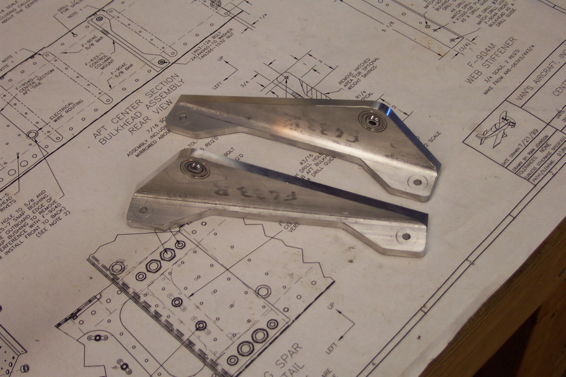
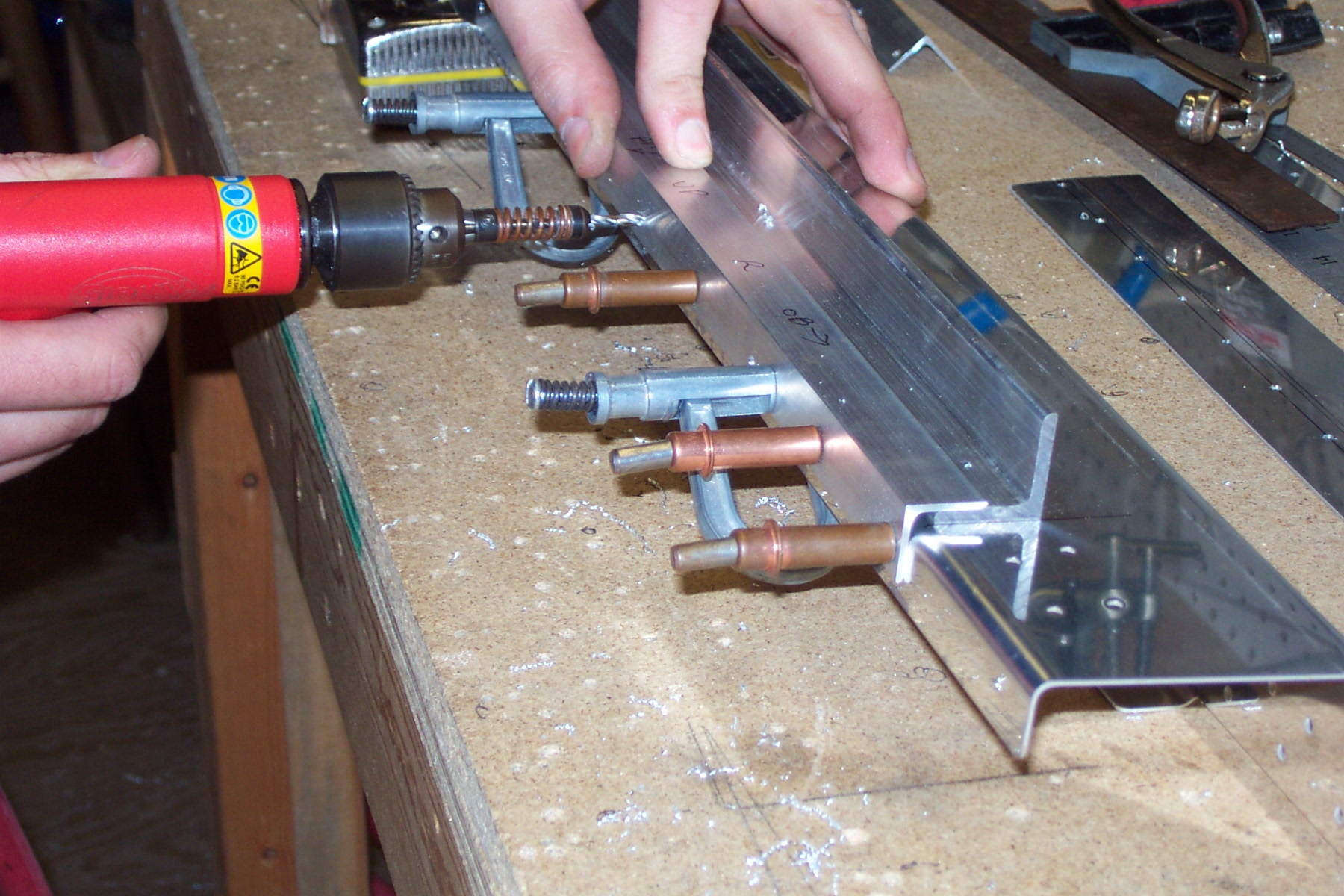
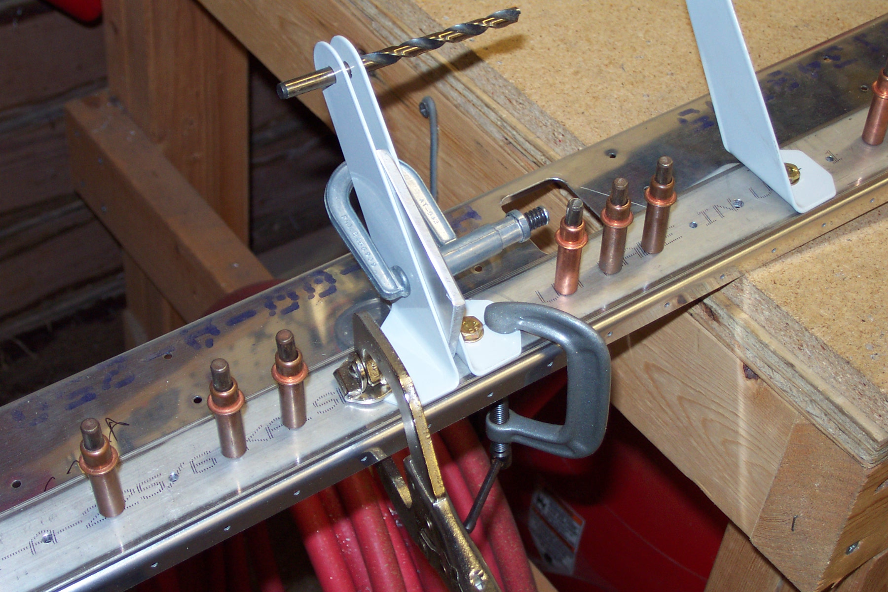
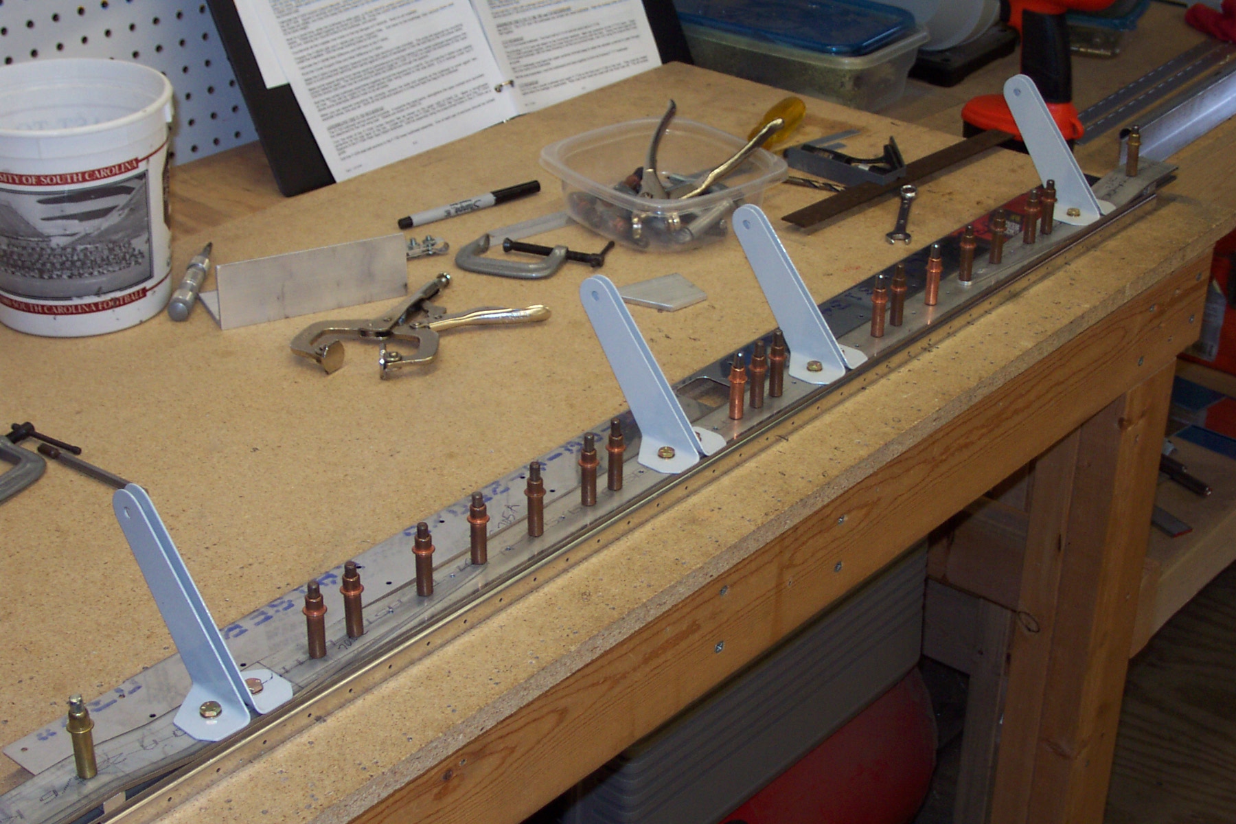
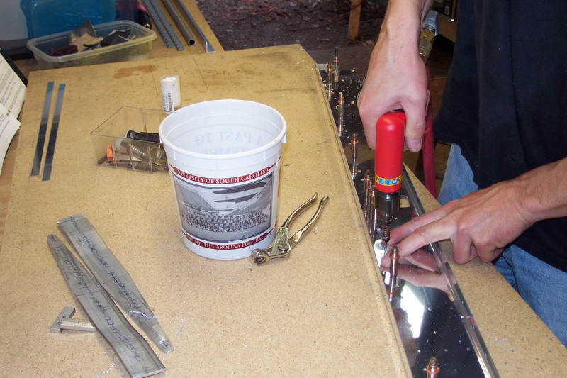
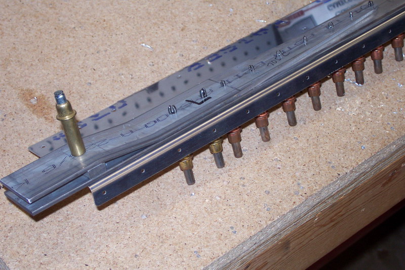
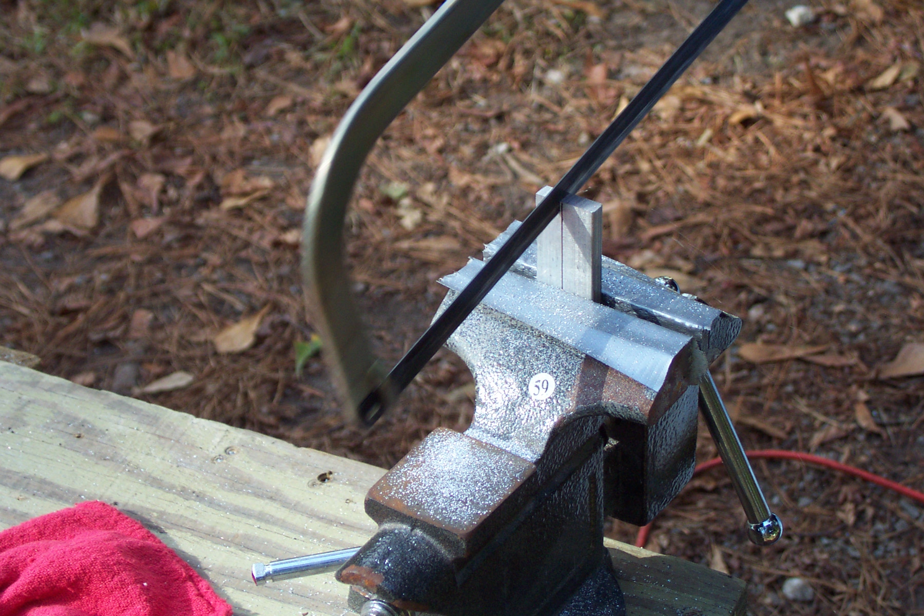
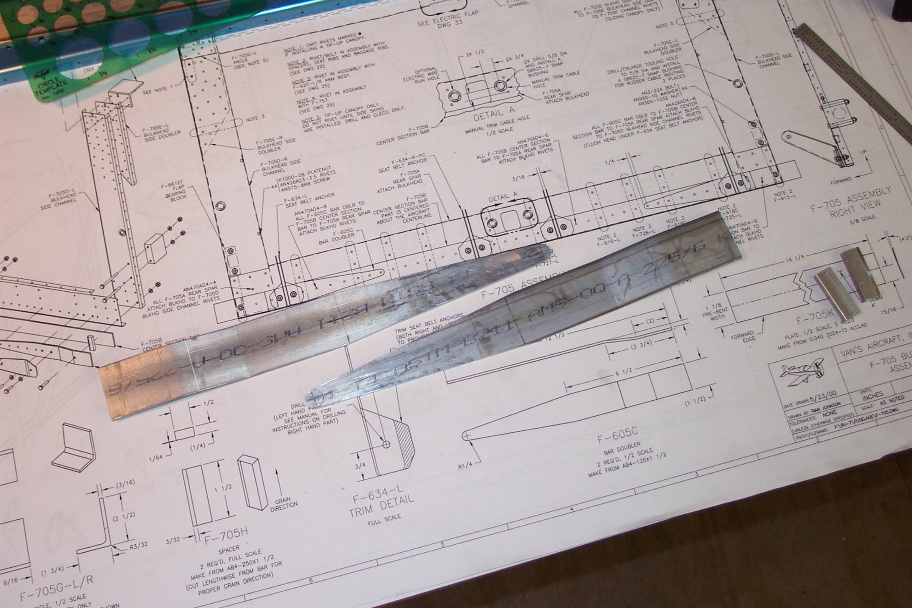
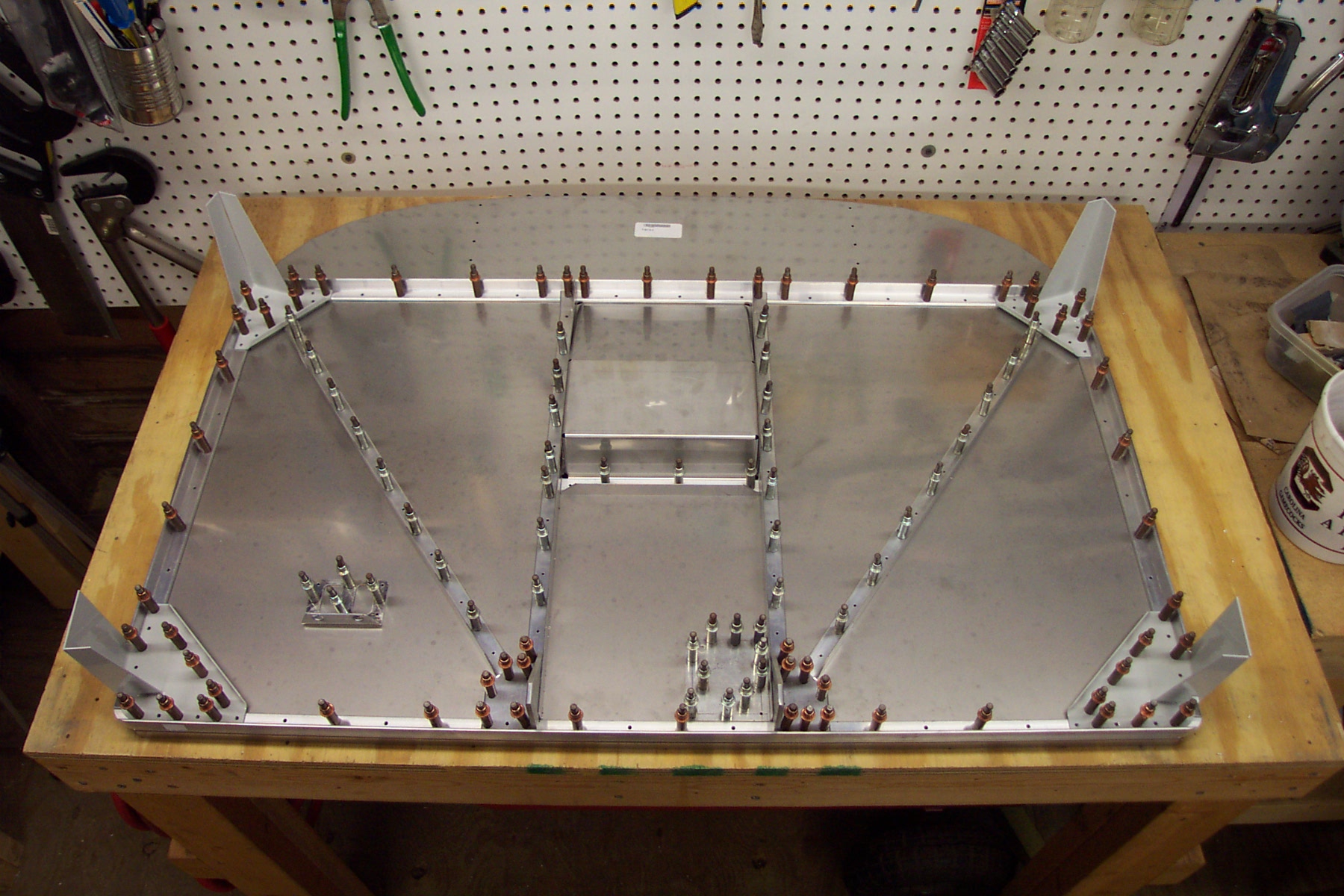
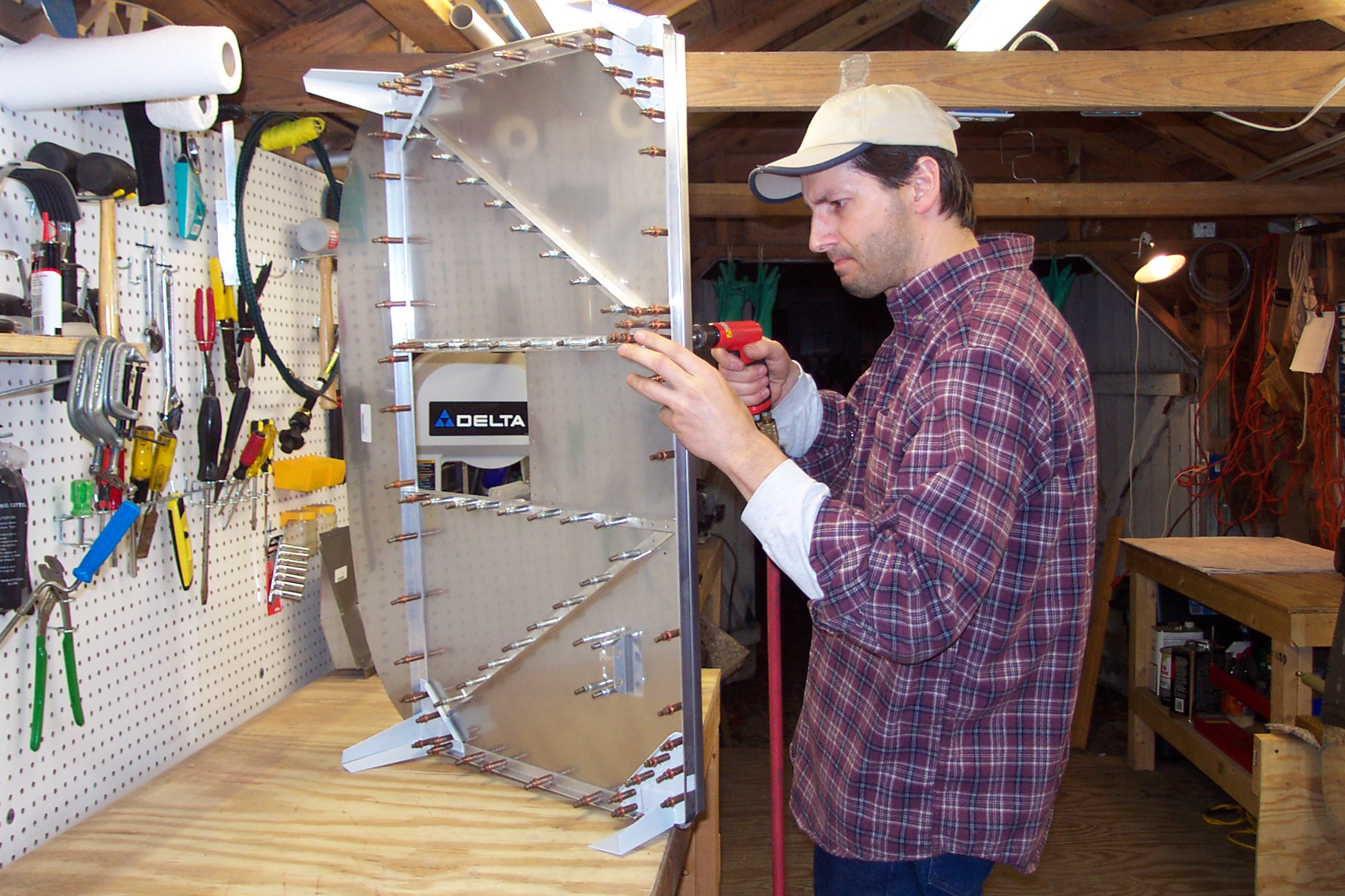
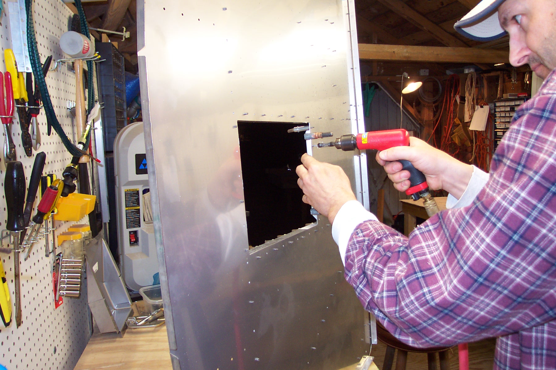
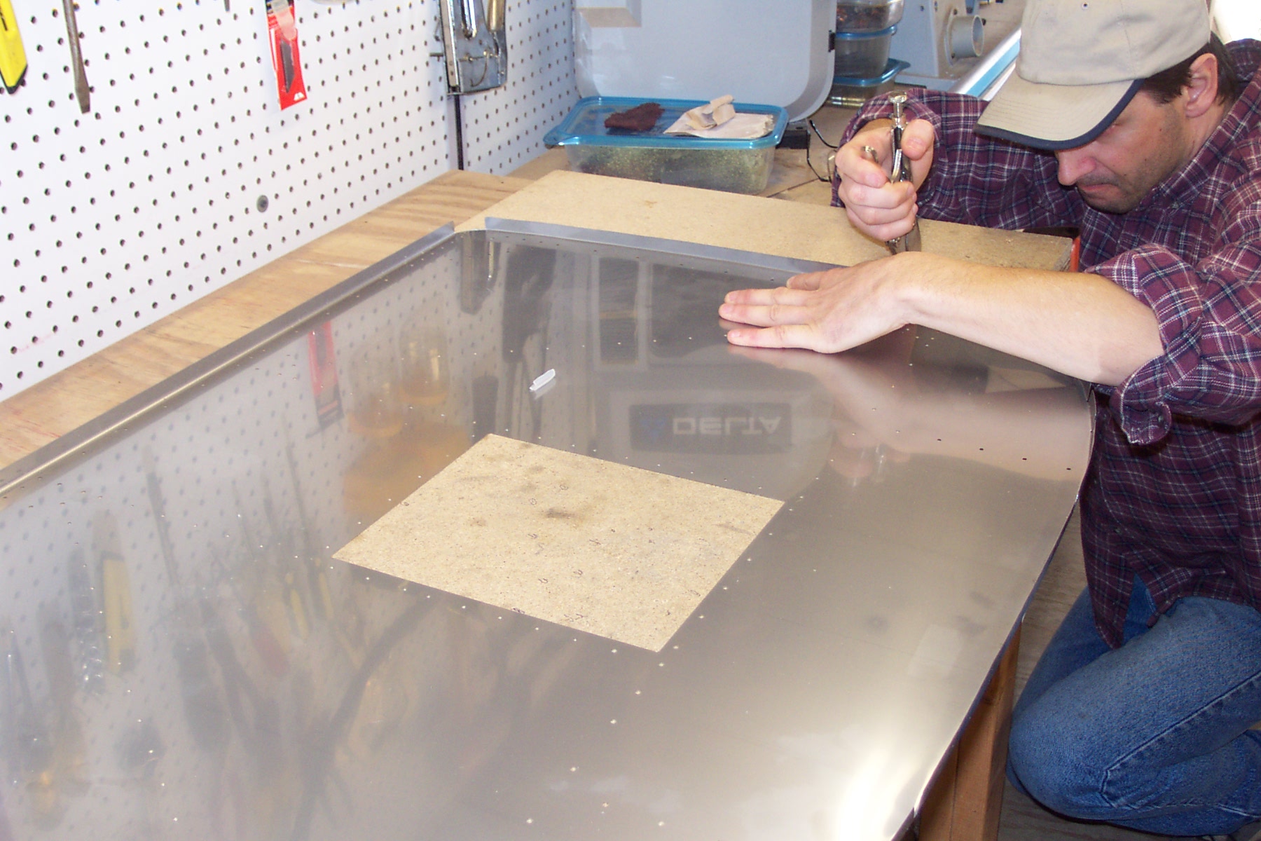
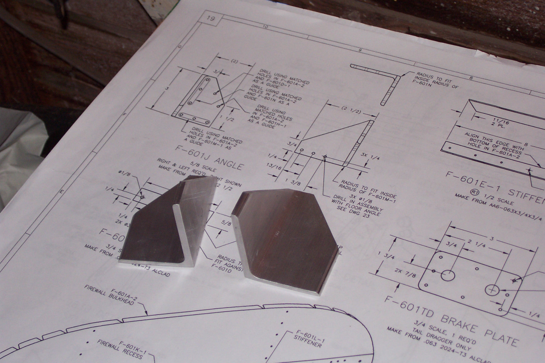
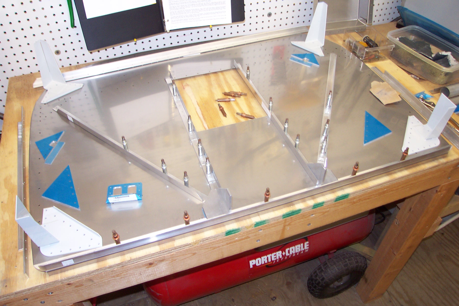
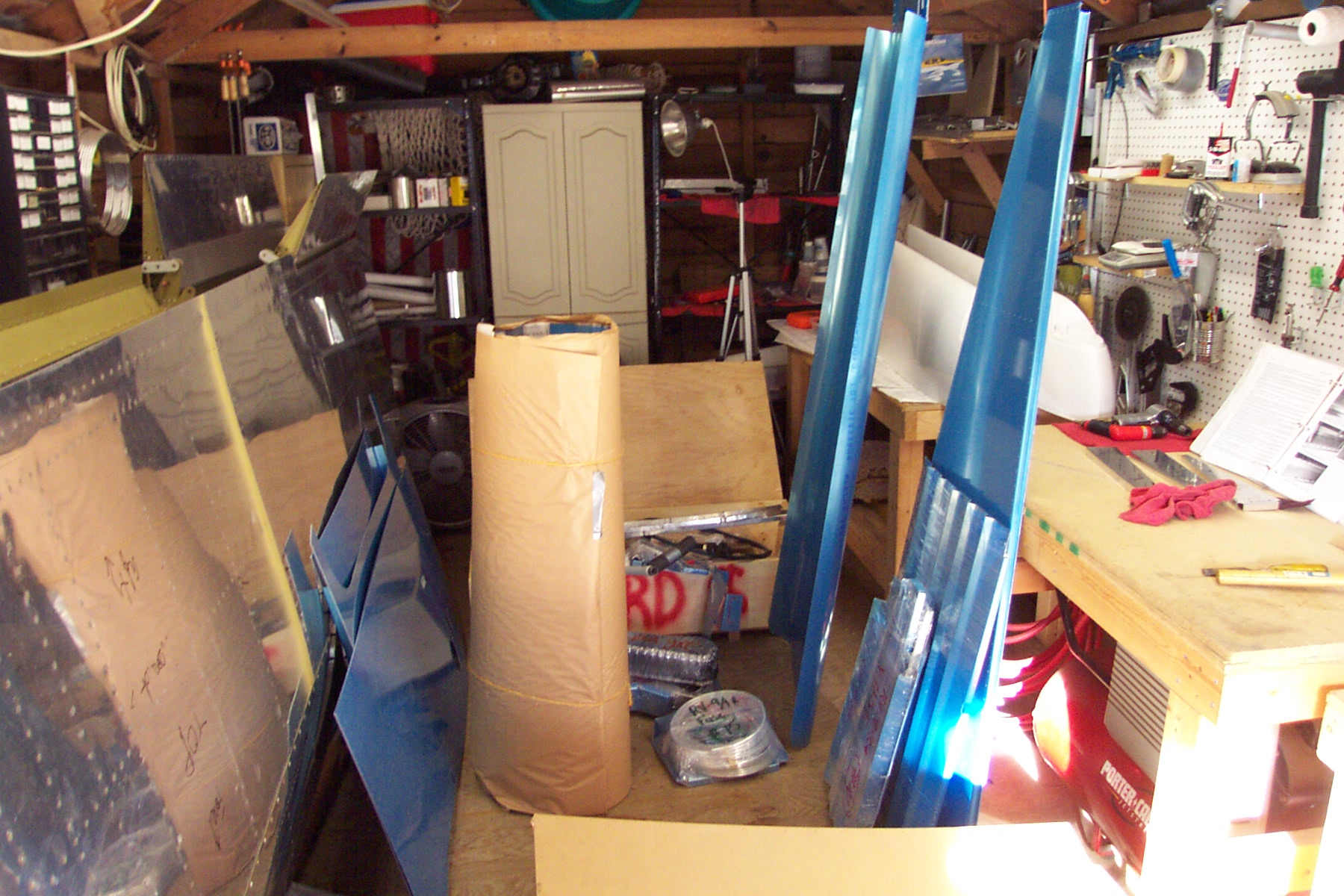
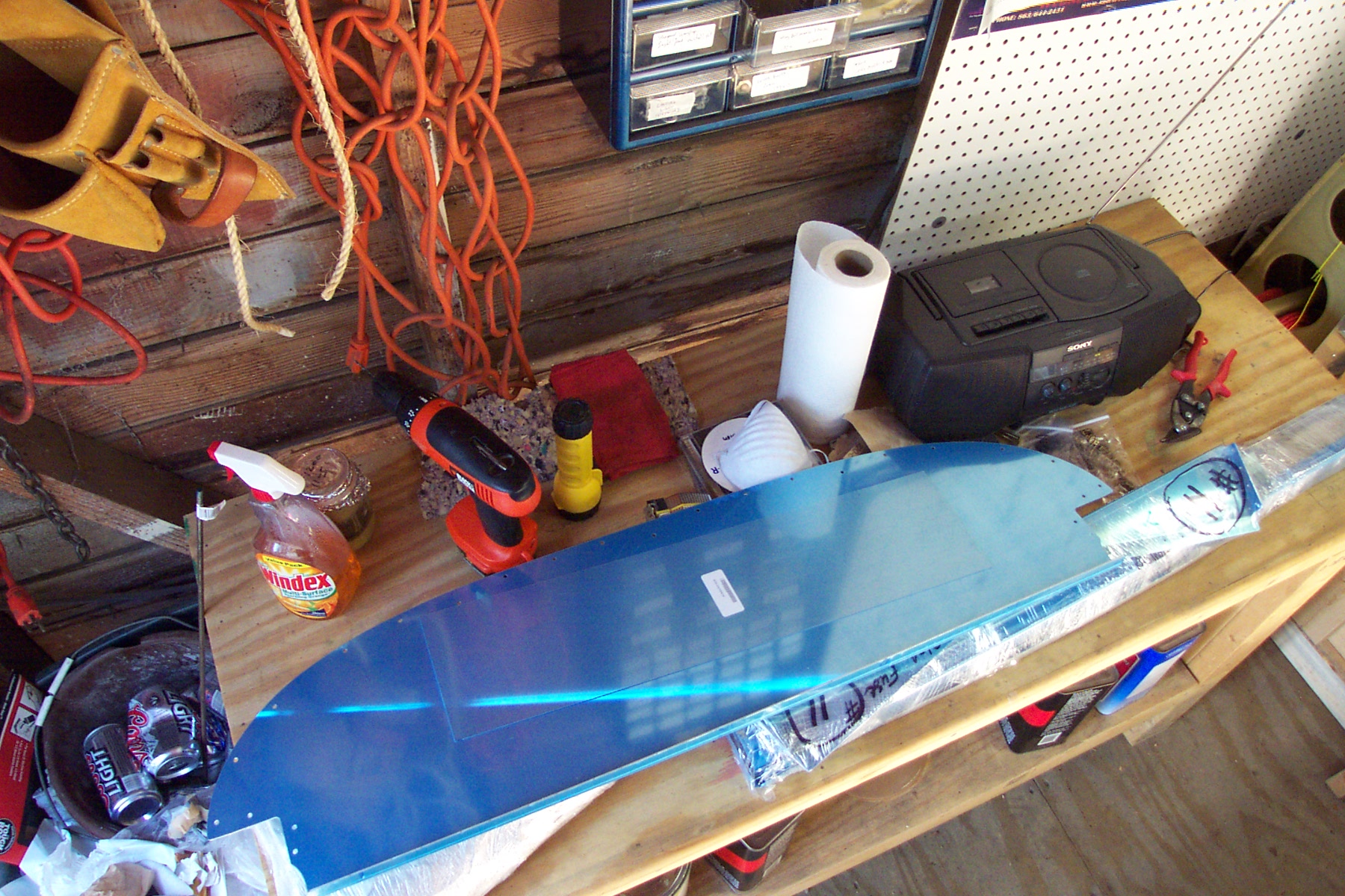
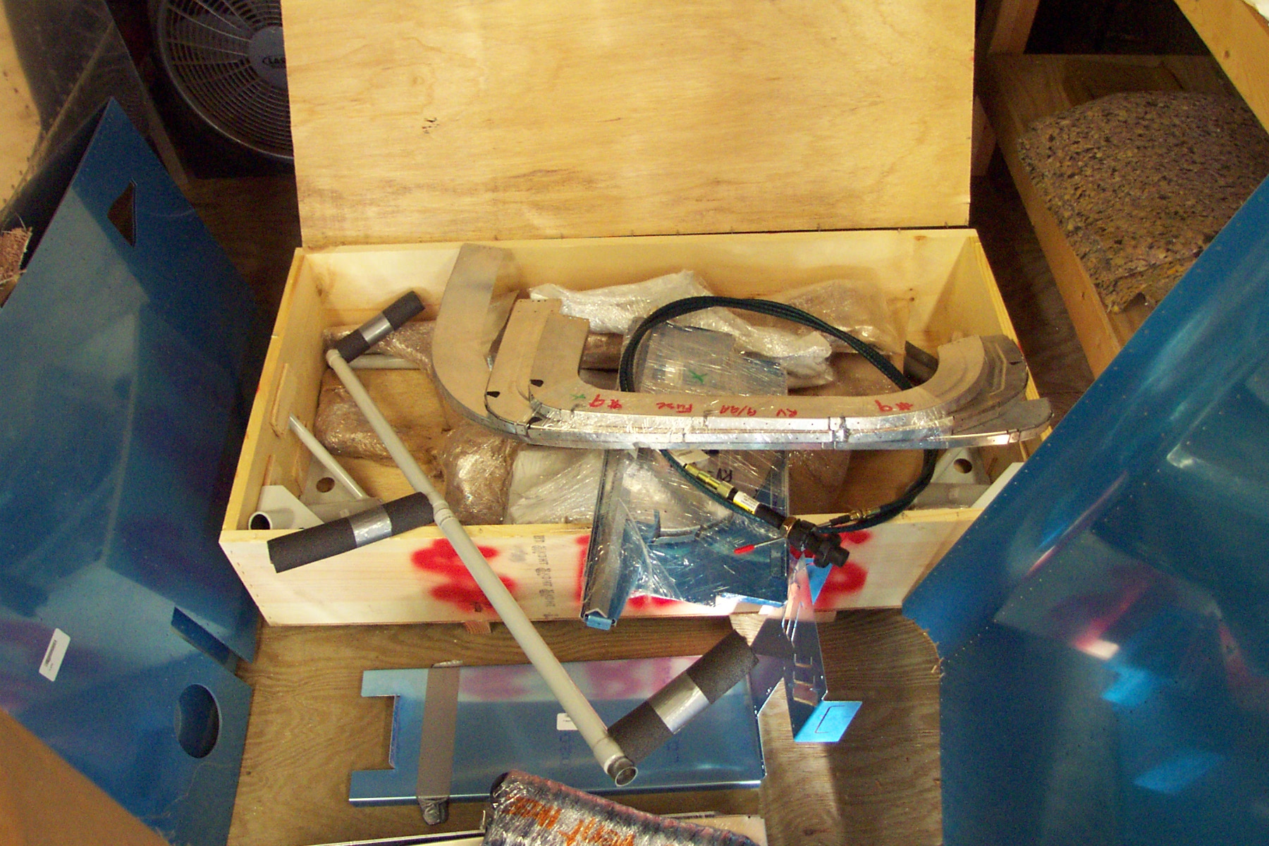
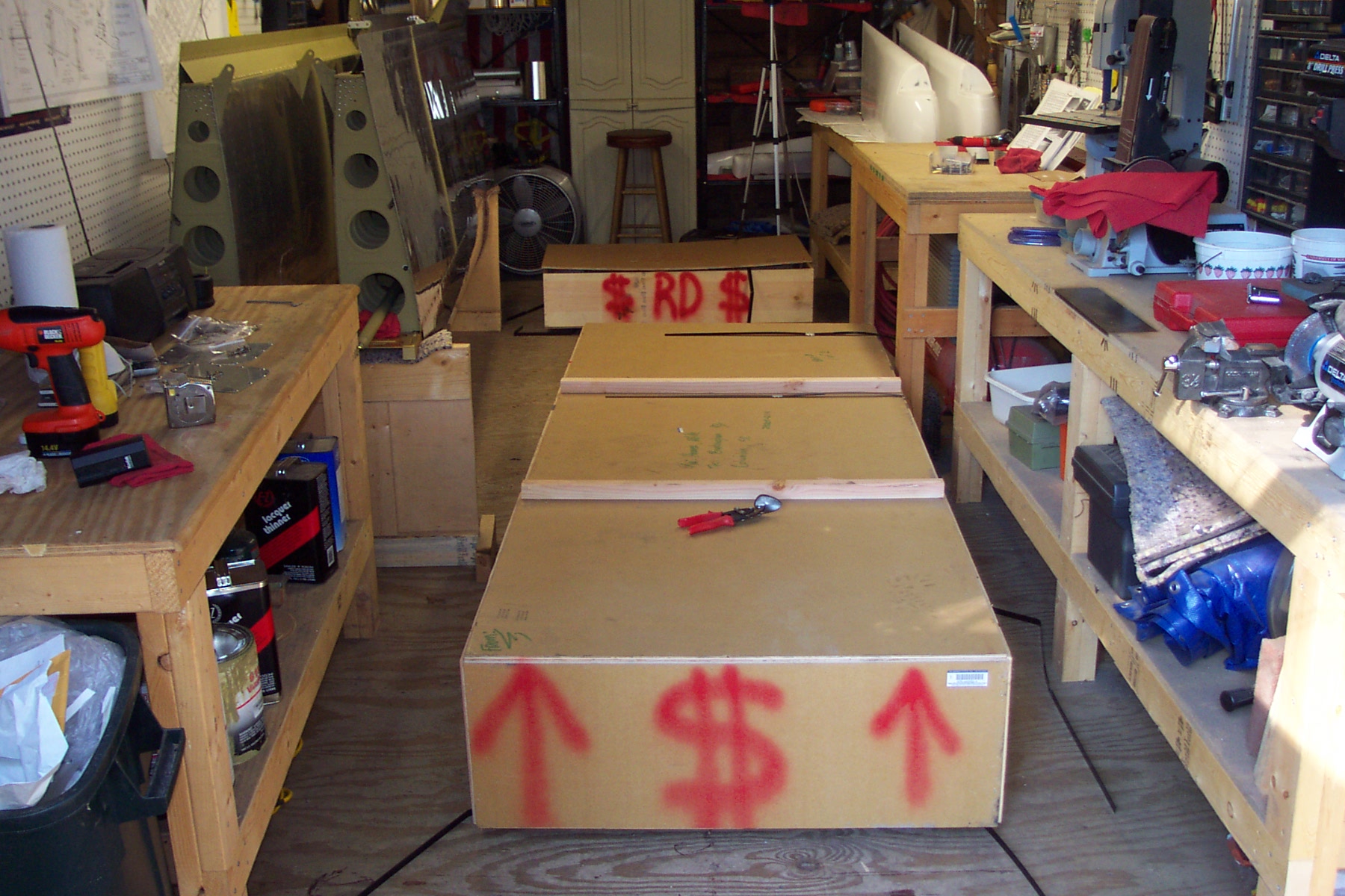