|
|
|
|
|
|
Official building time: 2224.3 hours.
|
|
|
Building time for Empennage: 193.7 hours.
Number of records for Empennage: 79. |
|
2006-07-10 |
Hours: 2.5 |
Category:
Empennage
|
|
Manual Ref:
|
ID#:
920
|
|
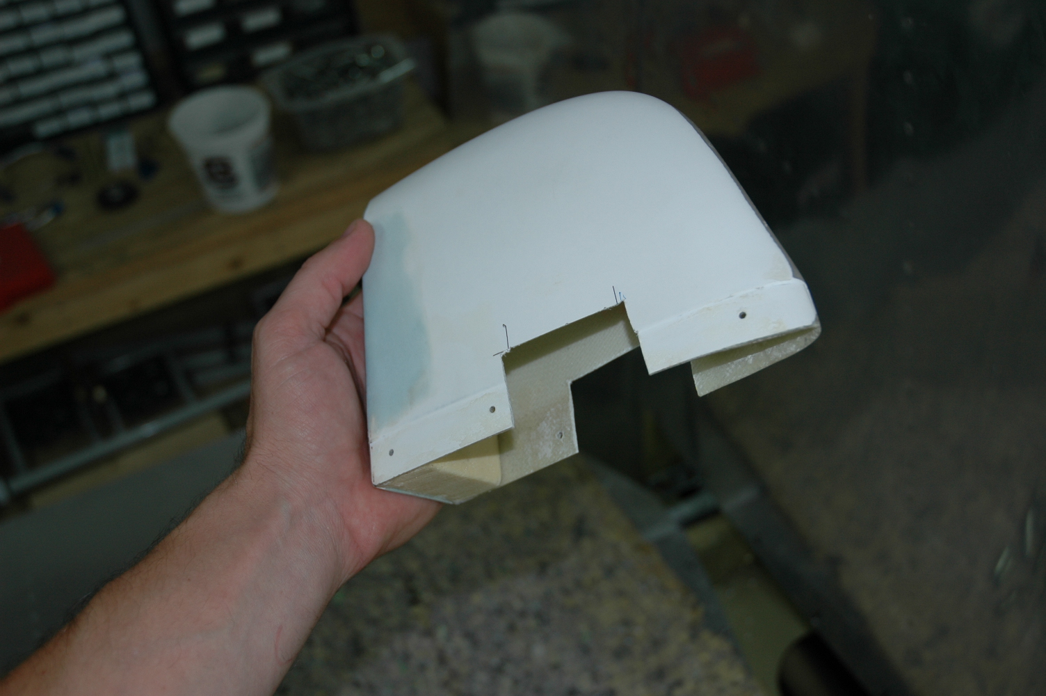
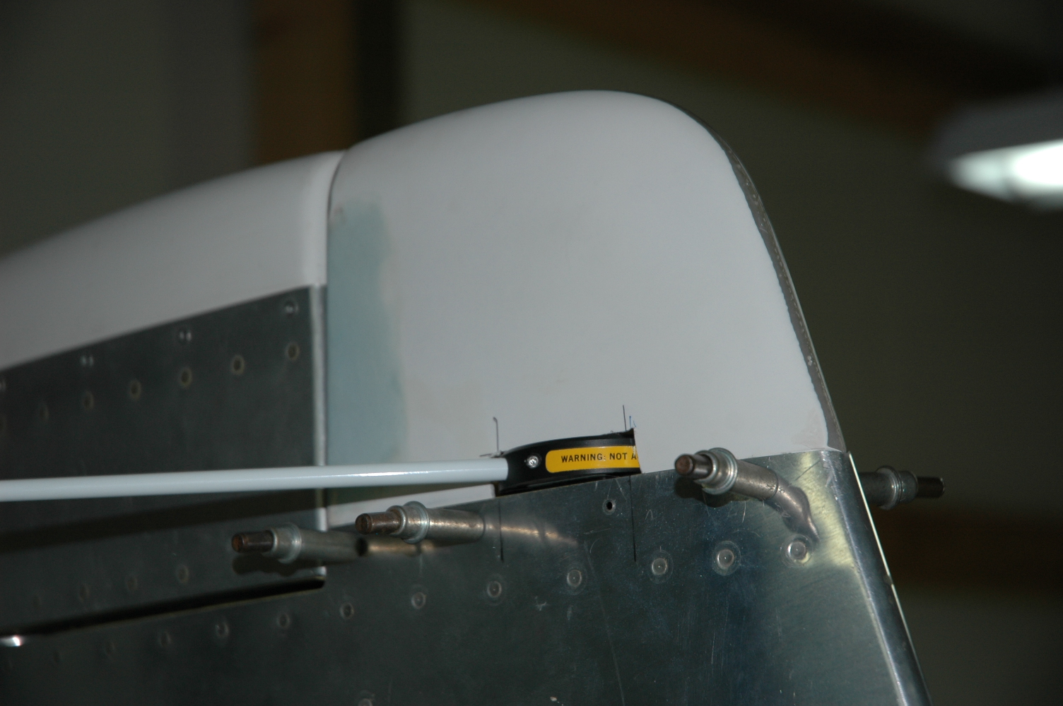
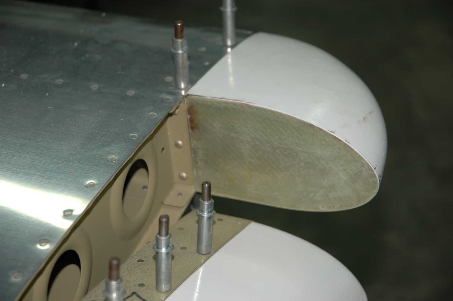
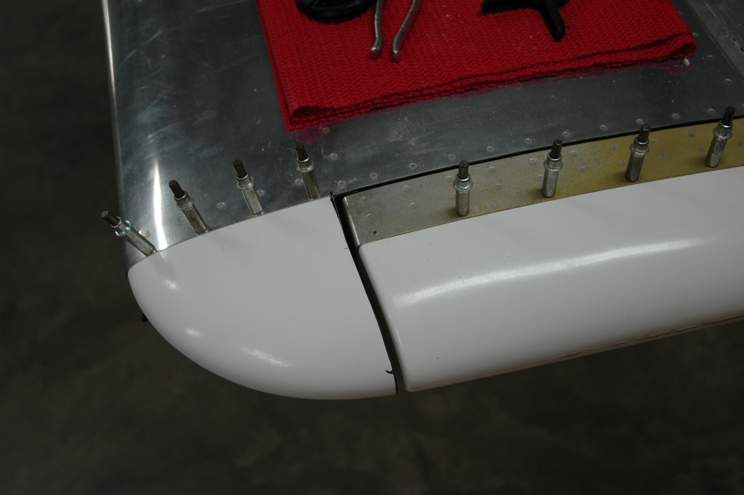
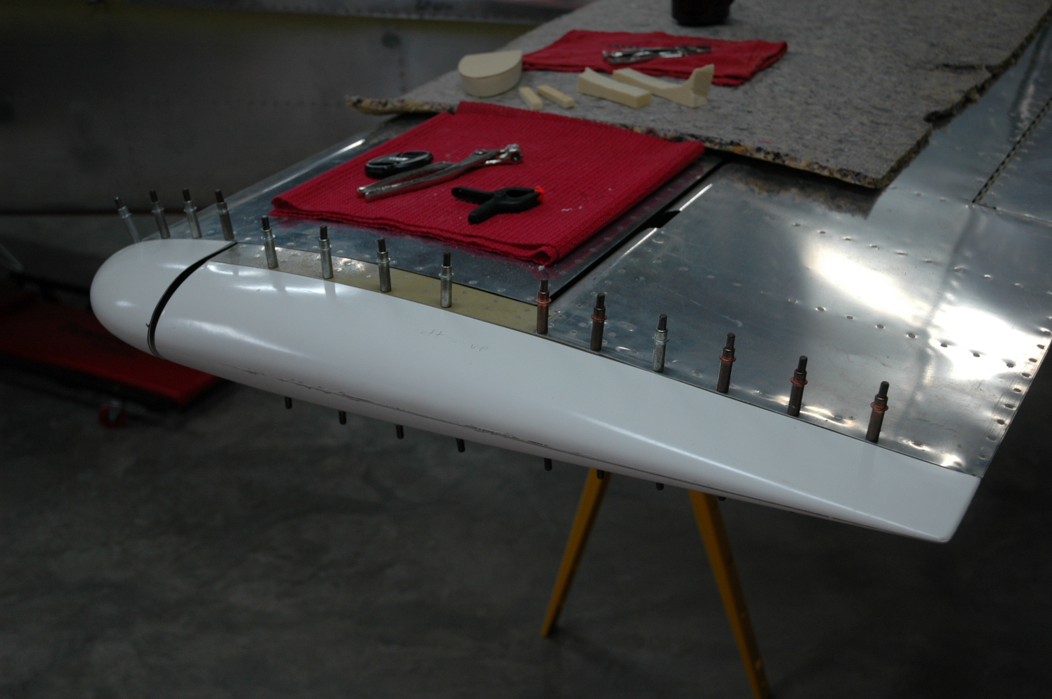
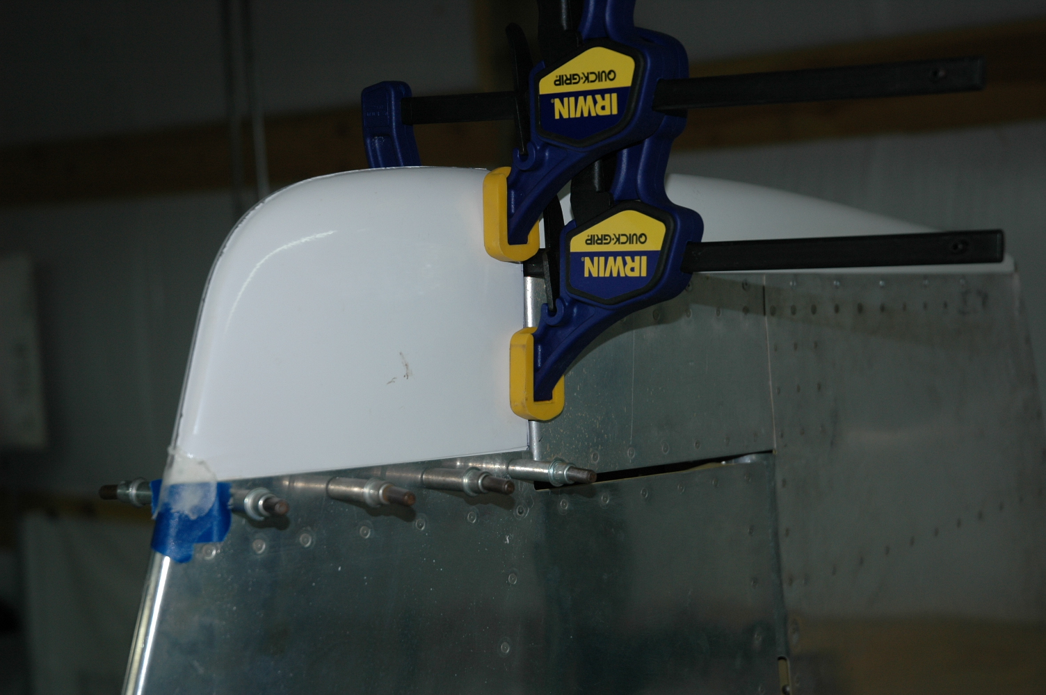
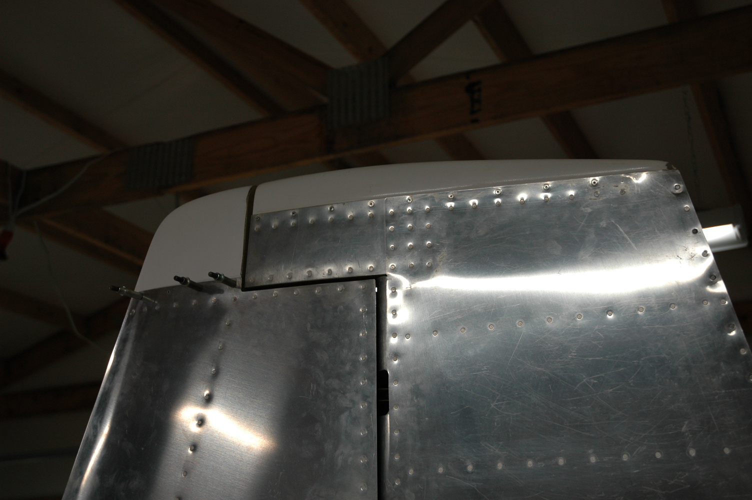
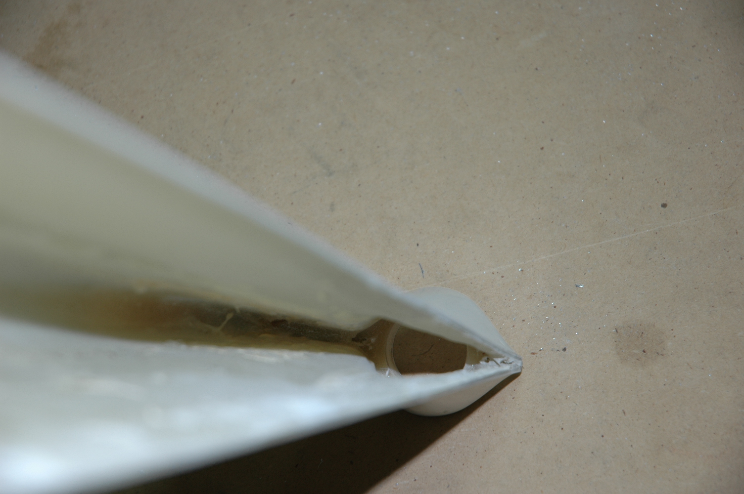
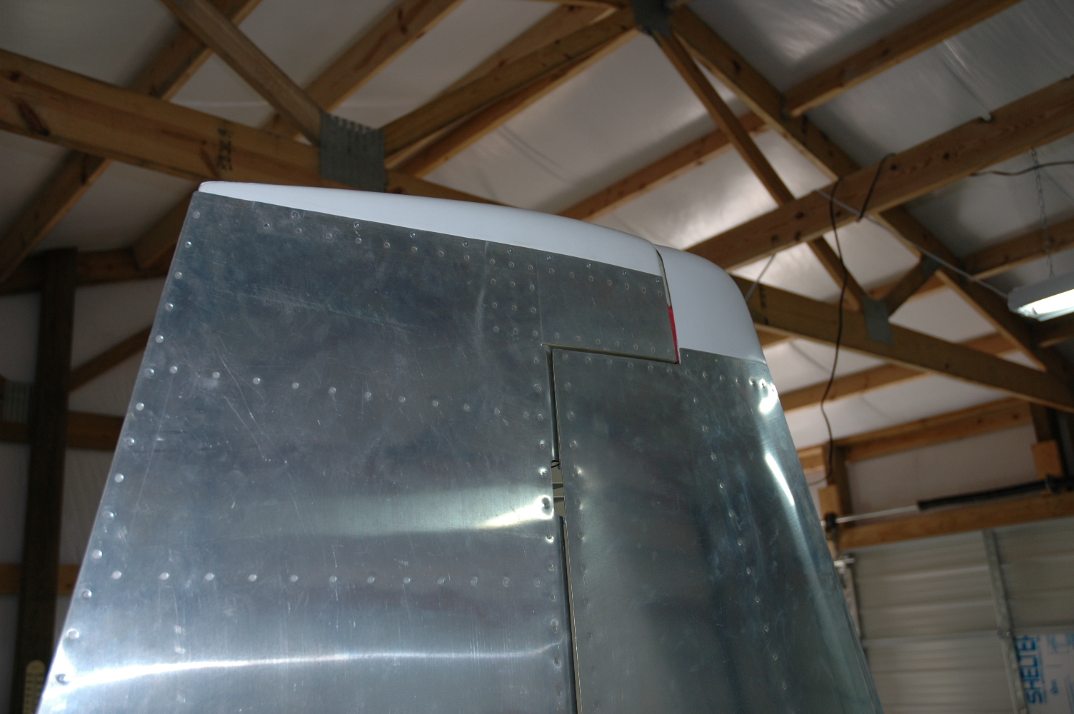
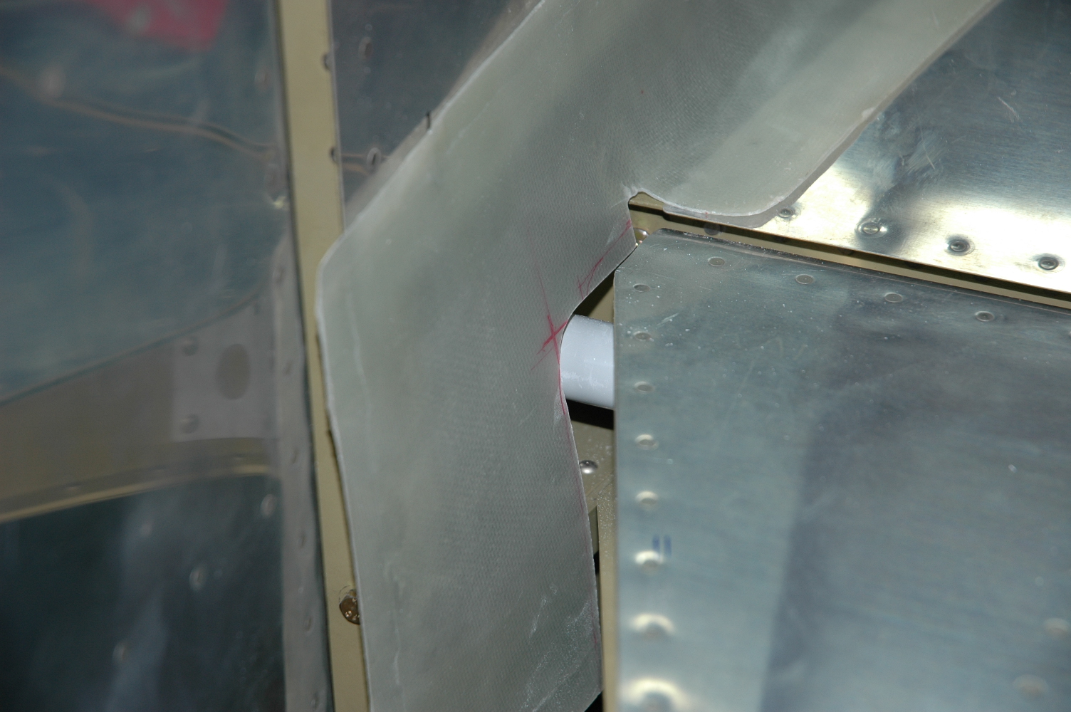
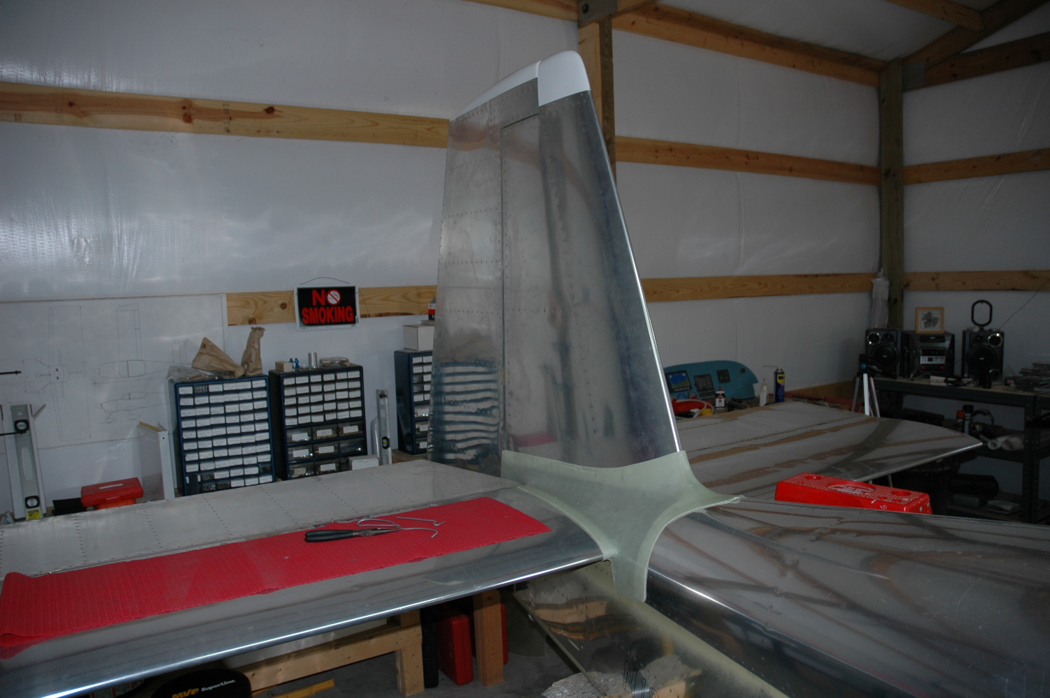
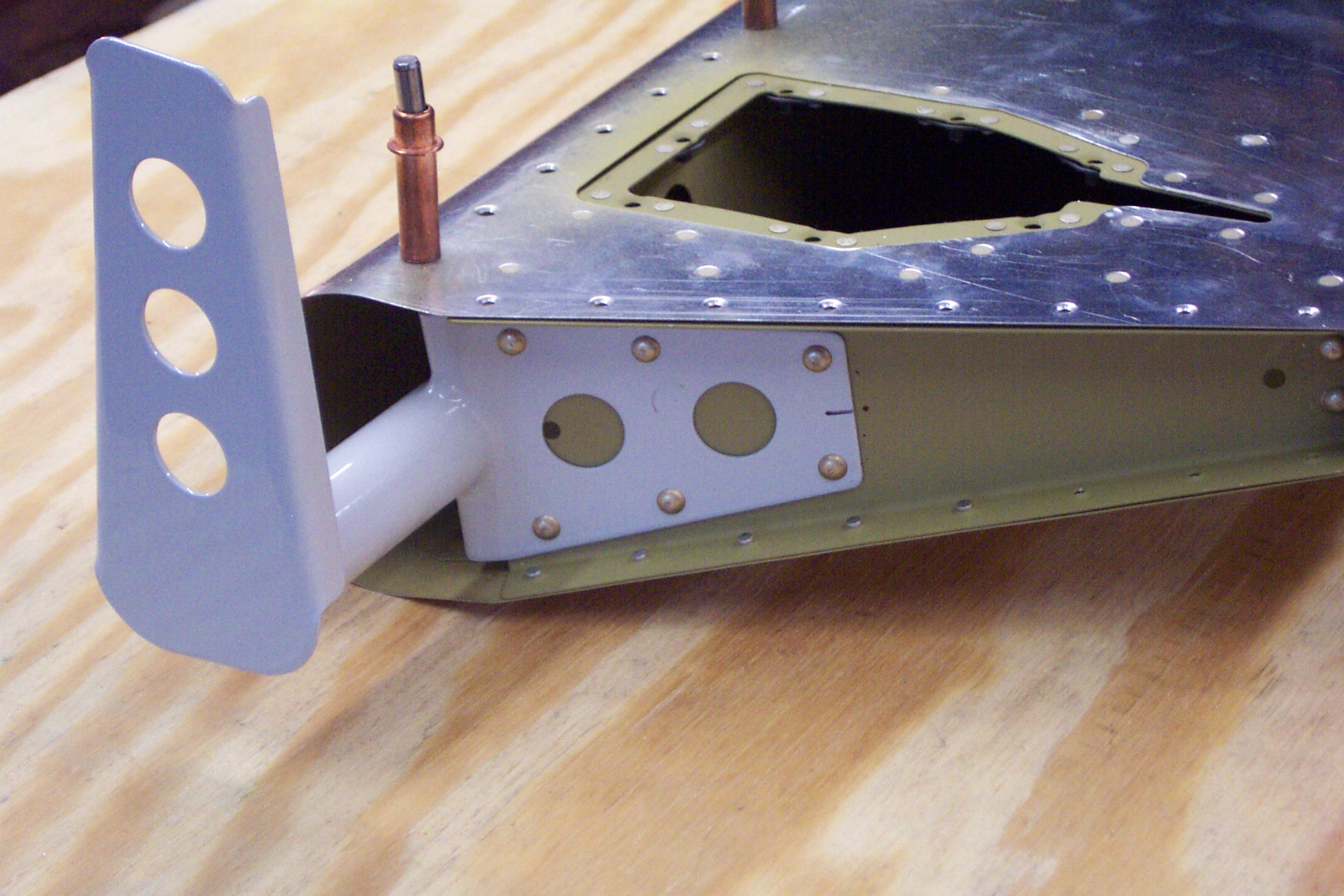
Mounted VOR antenna, modified VS tip |
|
Drilled and clecoed the VOR antenna submount and then drilled and enlarged the cable thru hole in the rudder tip rib. Pop riveted the mount, installed the VOR antenna and marked the cut lines on the VS tip. Trimmed away and fitted the tip. Thought about maybe adding glass to cover the VOR antenna "puck". Will contemplate that for awhile. Not sure it will be necessary or desirable.
|
|
|
2006-07-04 |
Hours: 4 |
Category:
Empennage
|
|
Manual Ref:
|
ID#:
918
|
|
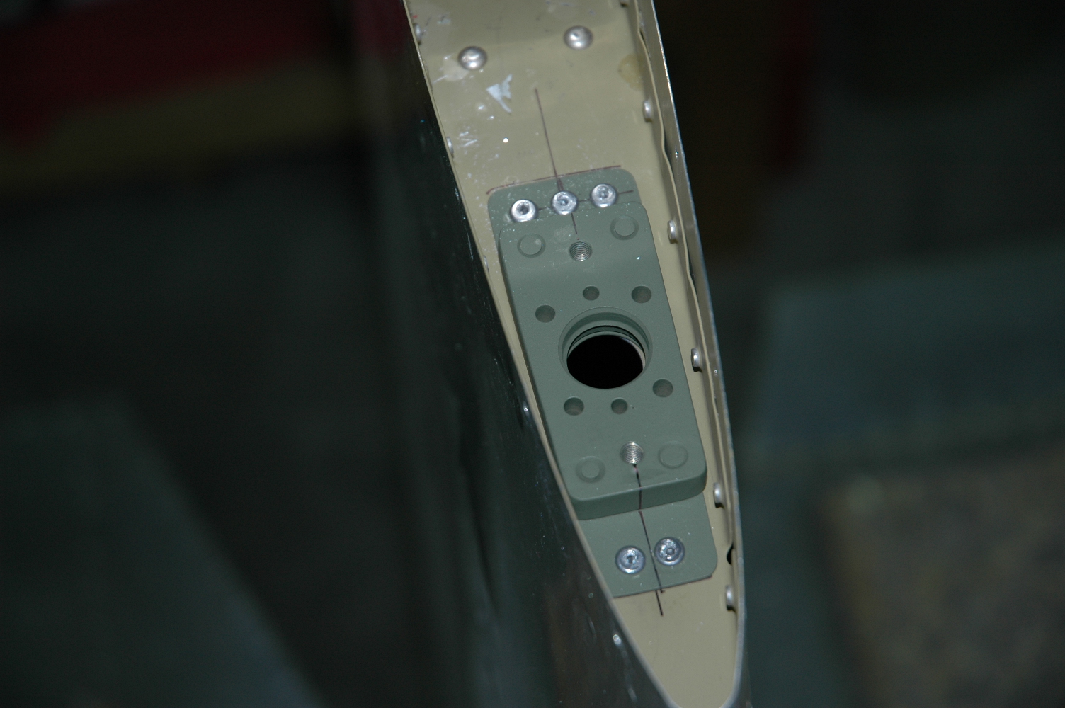
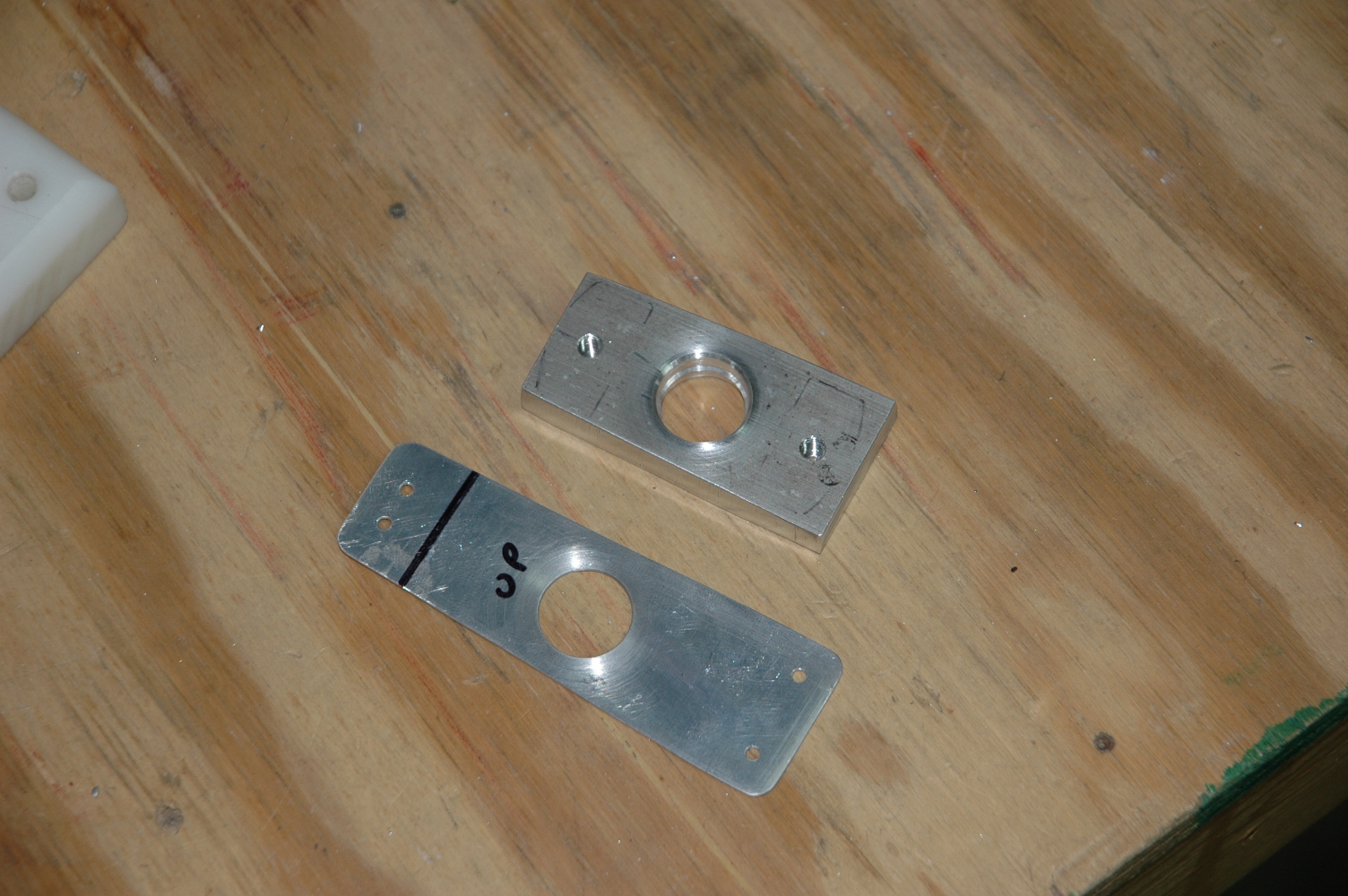
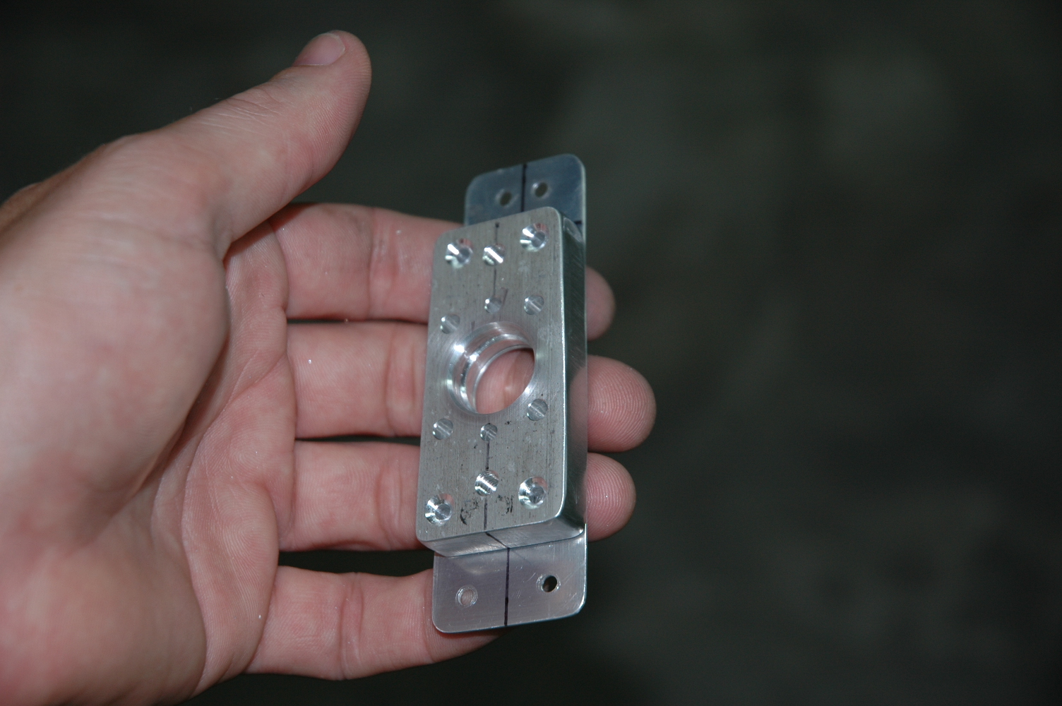
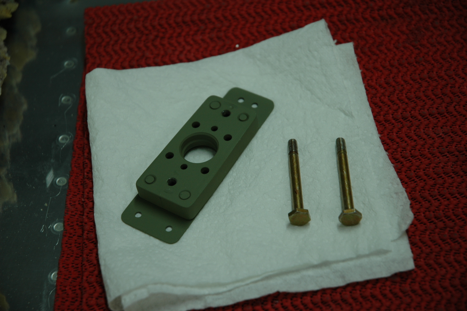
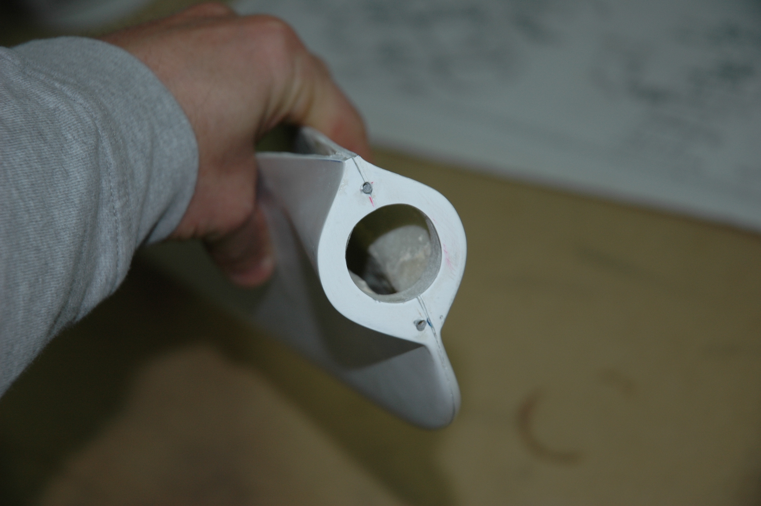
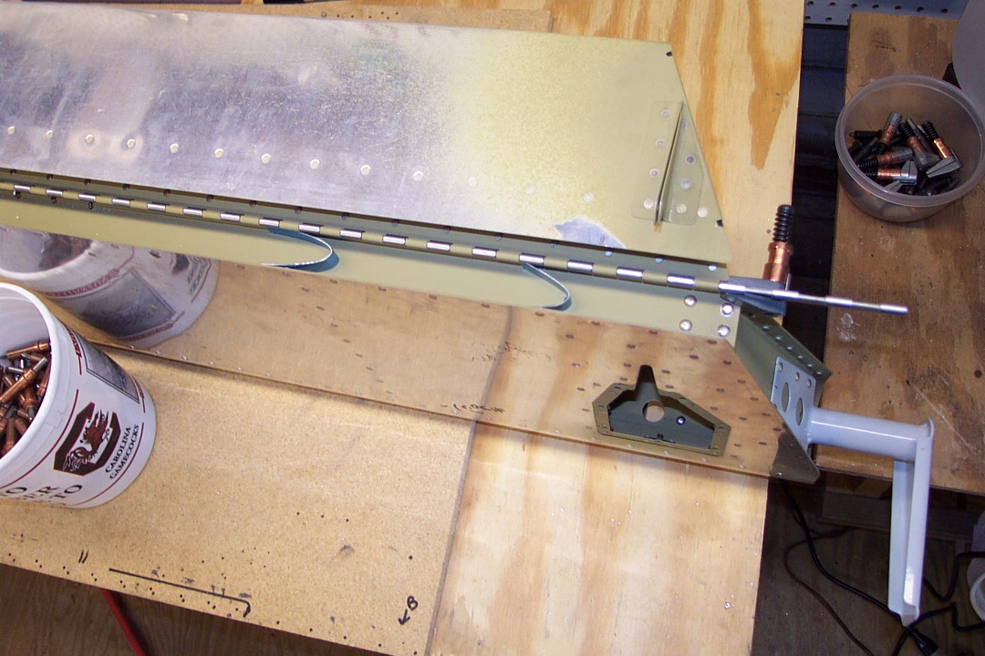
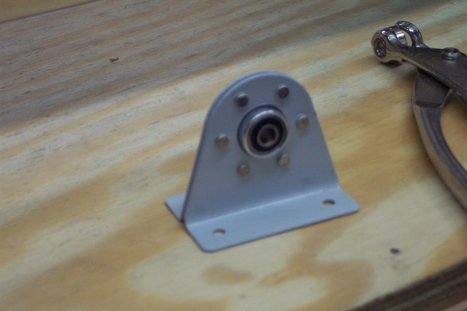
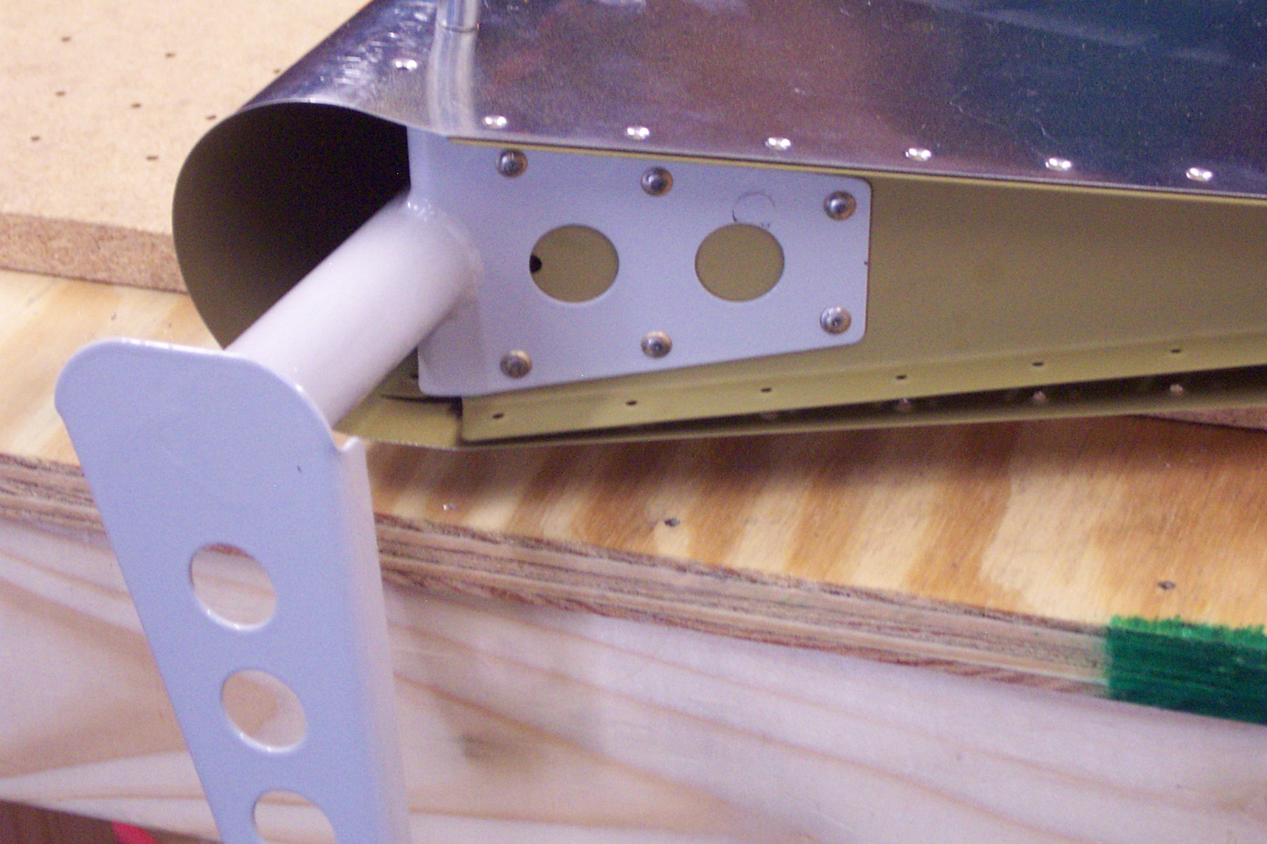
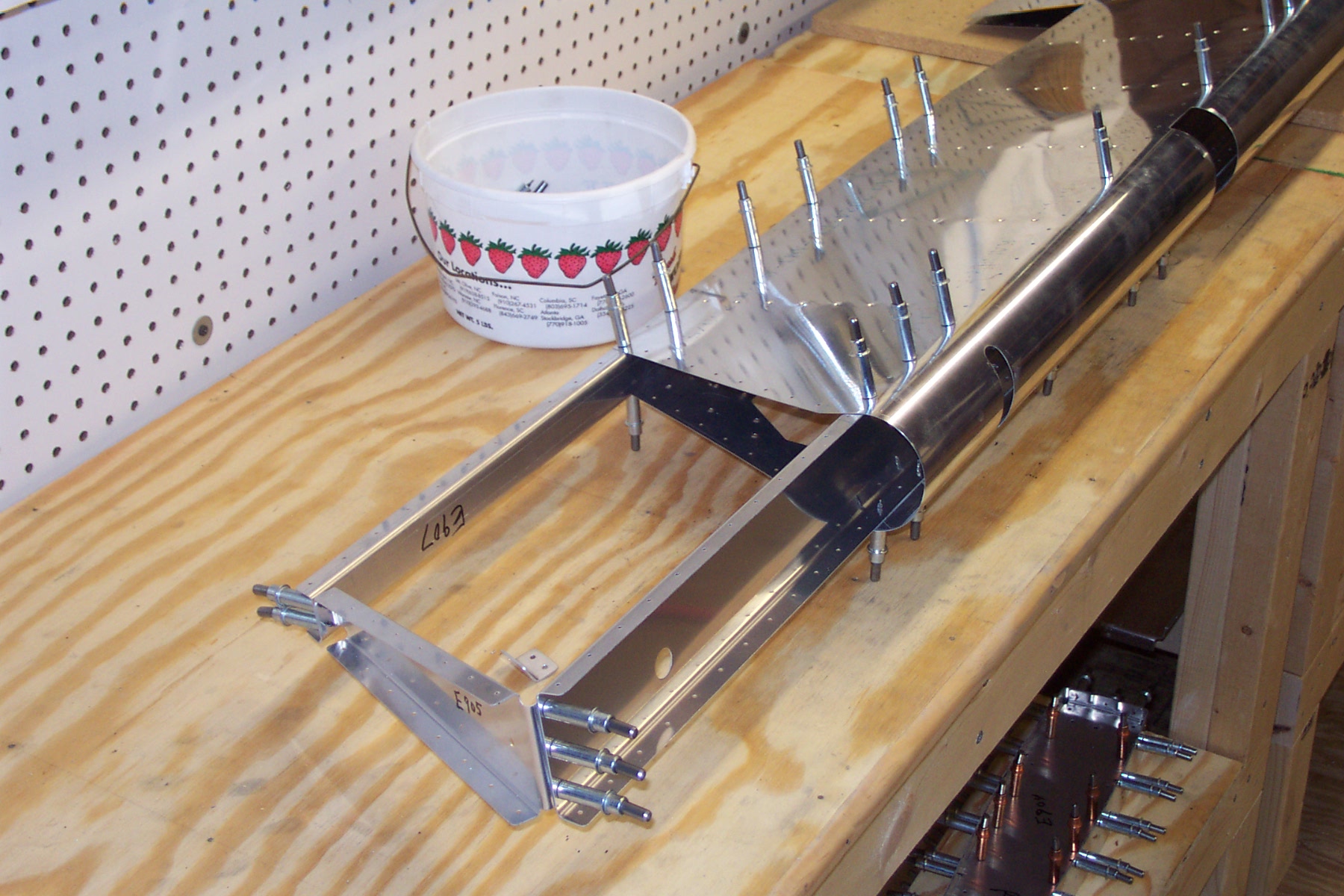
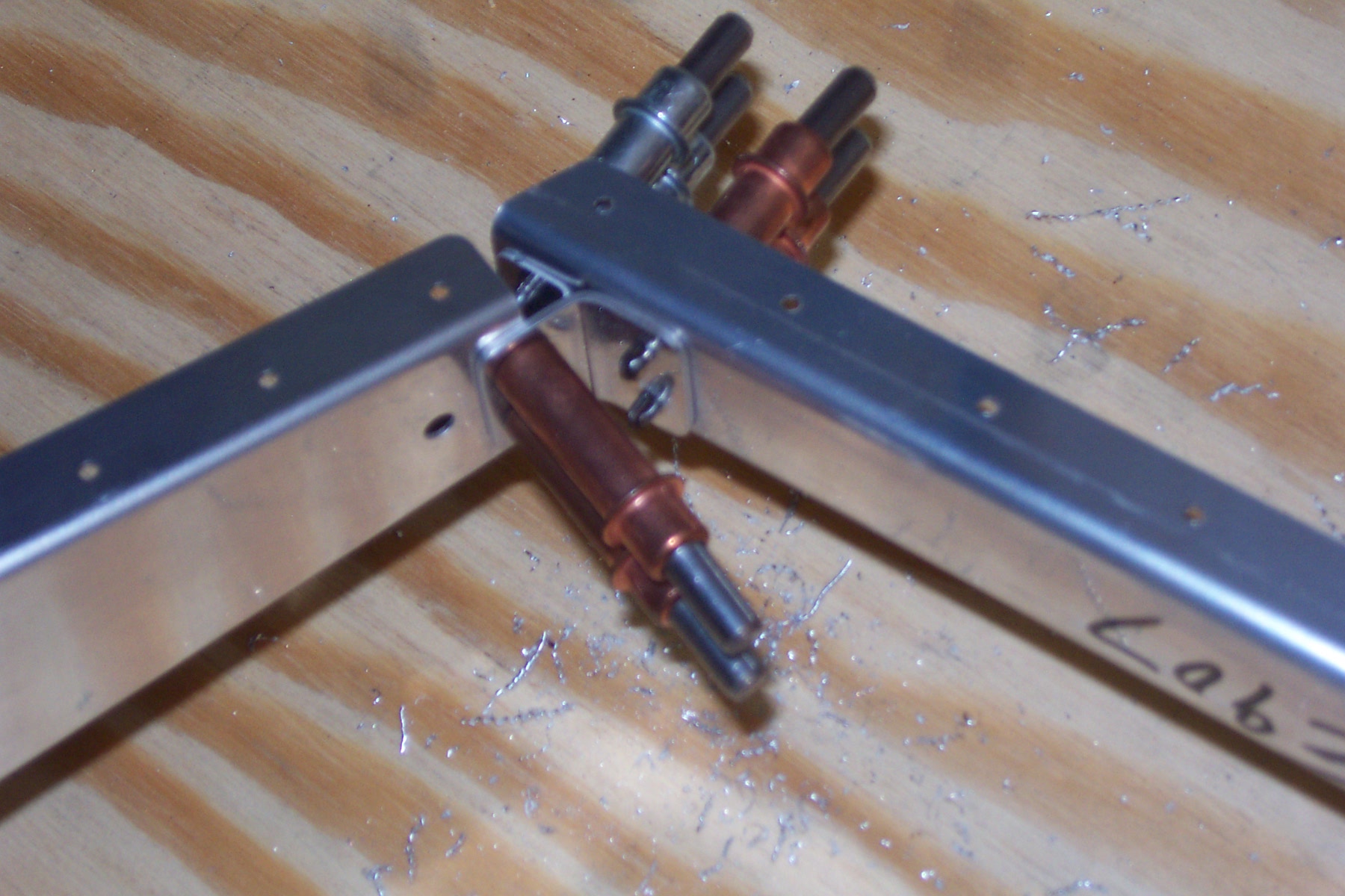
Worked on making the VOR antenna mount |
|
Recieved the 3/8" thick bar from Aircraft Spruce I need to make my VOR antenna mount. Did a bunch of head scratching and planning to design the mount. Cut and shaped the pieces, countersunk and drilled the center hole. Threaded the bolt holes for the AN3-16A bolts and drilled a few other lighten holes. Cleaned, primed and assembled the submount.
|
|
|
2006-07-02 |
Hours: 1.5 |
Category:
Empennage
|
|
Manual Ref:
|
ID#:
919
|
|
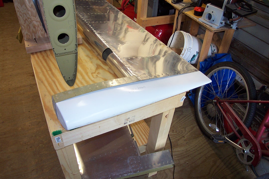
Got the aft side of the right HS tip glassed and ready to install.
|
|
|
2006-07-01 |
Hours: 2.5 |
Category:
Empennage
|
|
Manual Ref:
|
ID#:
917
|
|
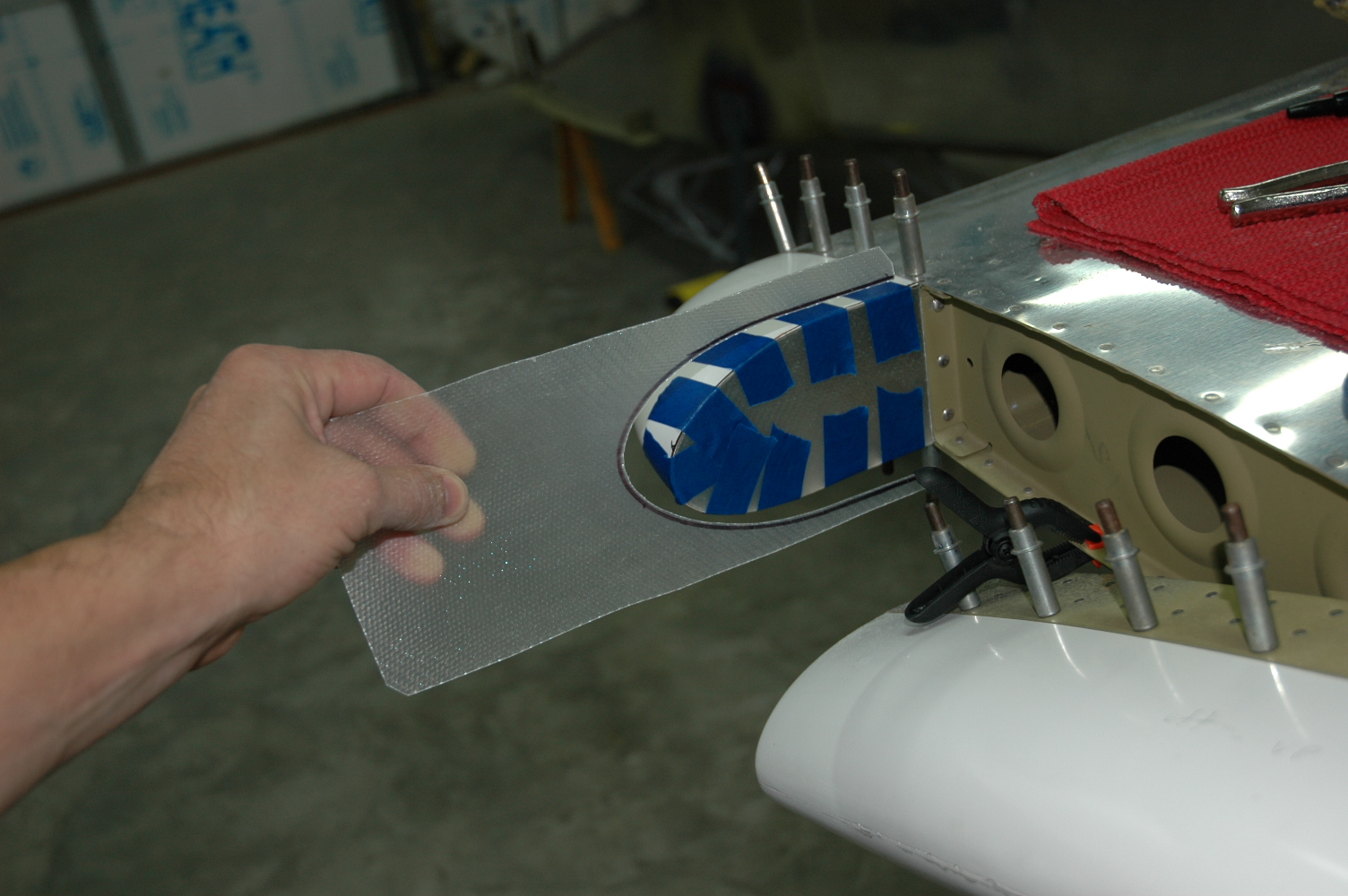
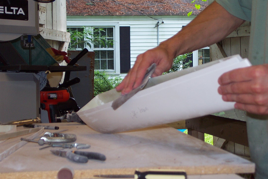
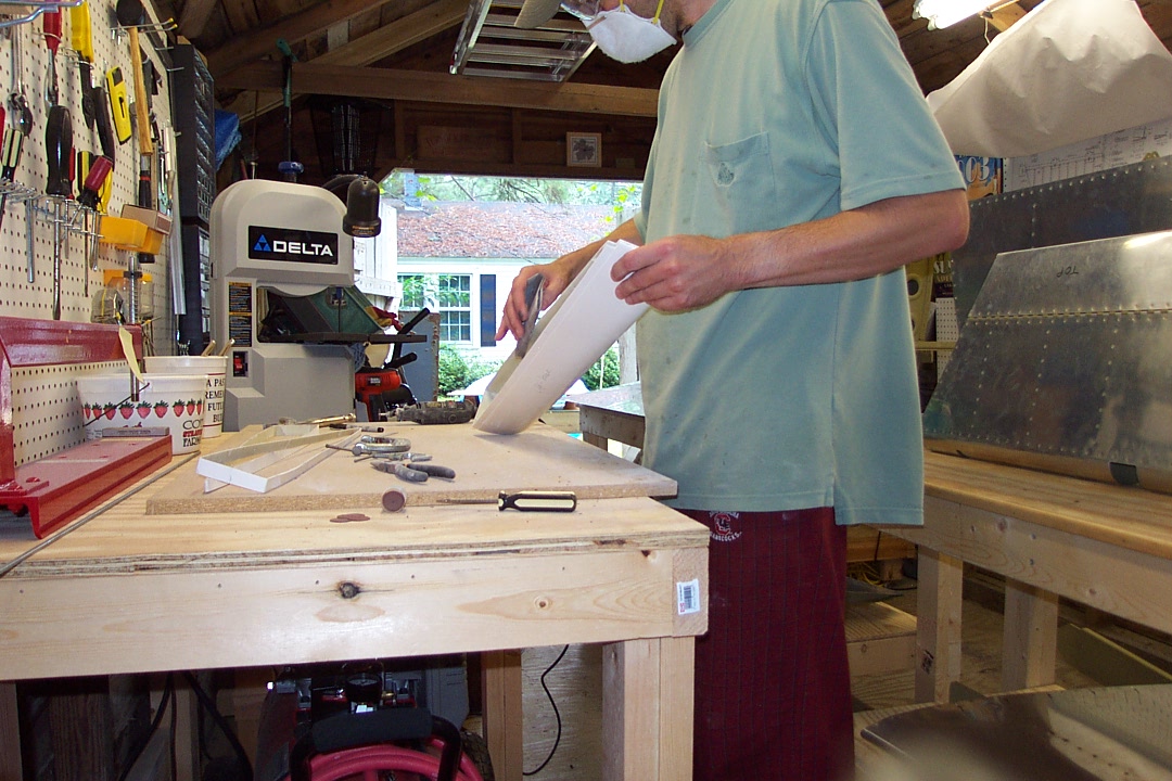
Glassed the left HS tip and started on the right one |
|
Glassed the aft of the left HS to form fillets inside to about two layers. Cut the sheet for the right tip and tacked/taped to the aft edge of the right HS tip. Will finished glassing/reinforcing it tomorrow.
|
|
|
2006-06-30 |
Hours: 1 |
Category:
Empennage
|
|
Manual Ref:
|
ID#:
916
|
|
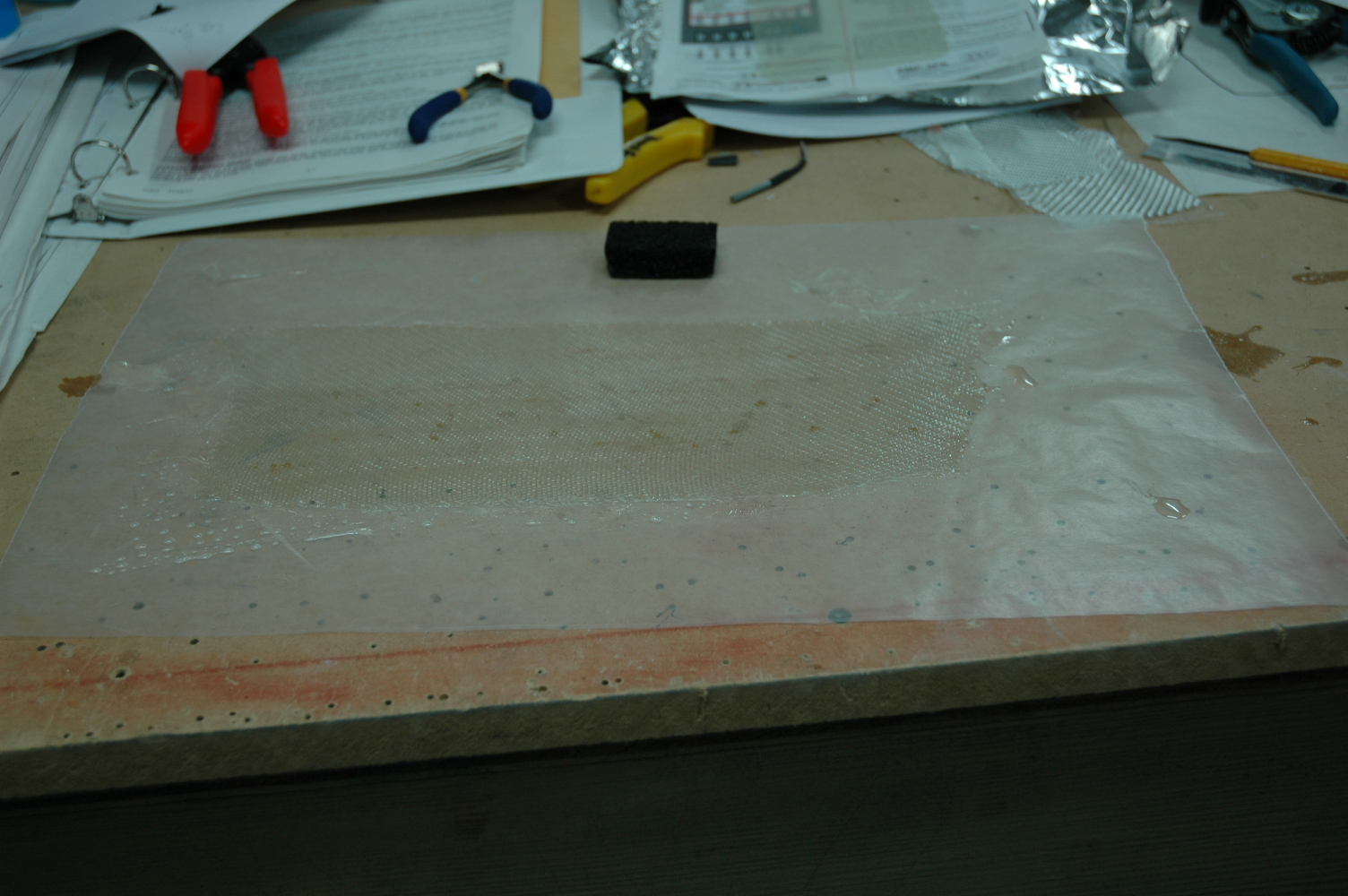
Laid out another piece of fiberglass on wax paper this morning for the right HS tip. Didn't make a big enough piece for both HS tips the first time. Took the piece of fiberglass I set up last night and held it against the aft edges of the left HS tip and marked the cut pattern. I cut the piece out about a 1/16" inside the mark line with sharp scissors, dabbed leftover epoxy on the left HS aft edges and put the cut out fiberglass piece in place, held with painter's tape. I plan on strengthening from the inside by glassing around where the piece contacts HS tip edges. More later...
|
|
|
2006-06-29 |
Hours: 2.5 |
Category:
Empennage
|
|
Manual Ref:
|
ID#:
915
|
|
Drilled and clecoed HS and elevator tips |
|
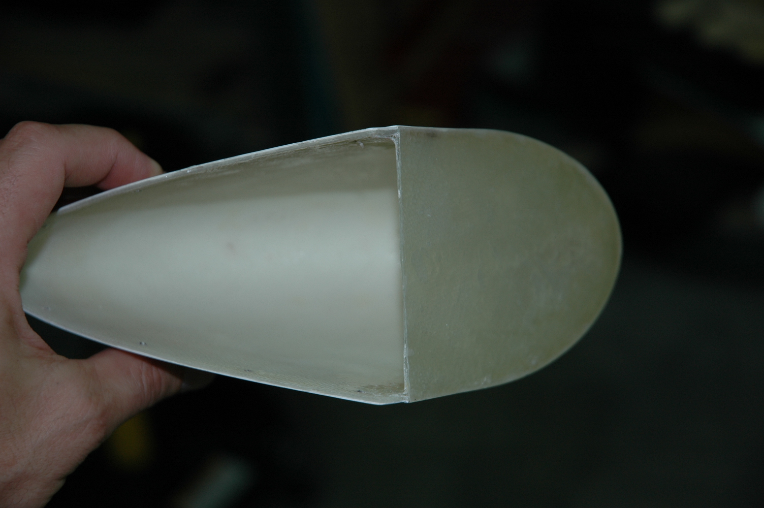
Fitted and drilled the elevator tips. Fitted and drilled the left HS tip. Cut the aft to the shape of the elevator forward end with about a 1/4" gap. Spent a lot of time cutting foam to put in the HS tip, but decided on another approach that I think will work. I laid a single layer of fiberglass/epoxy and let it set up. I plan on cutting it to the shape of the aft side of the HS tip and then tack-glue it to the aft edges of the HS tip, then glass it in nice and strong.
|
|
|
2006-06-27 |
Hours: 3 |
Category:
Empennage
|
|
Manual Ref:
|
ID#:
914
|
|
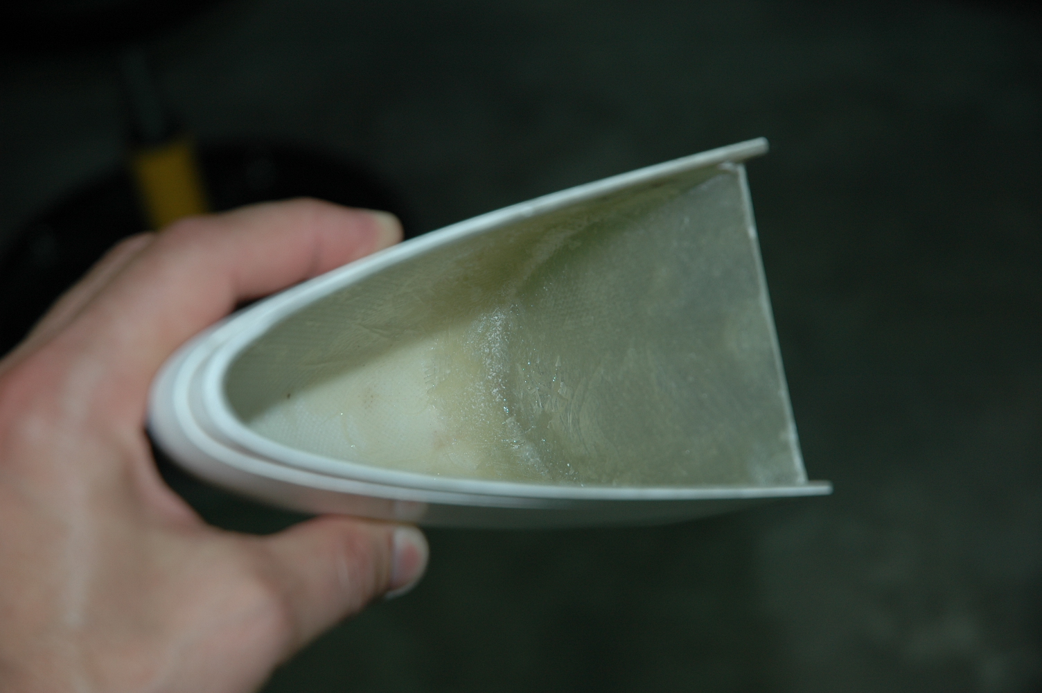
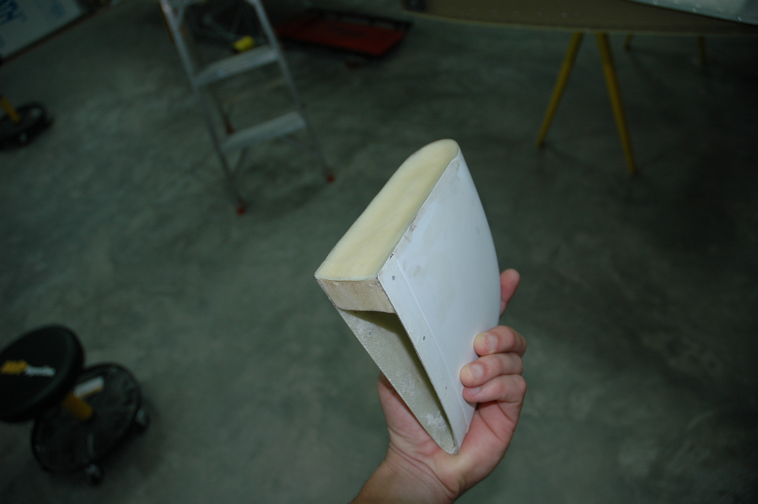
Fitted and fiberglassed the aft of the VS tip. Cut some foam and glued it in place with some epoxy, then filleted the edged with epoxy/flox and then glassed the aft end. It ended up with a concave surface. Also added a little flox mixture to the fore edge at the VS to fill a gap. Next to cut the slot to all for the antenna "hockey puck". I am using the Comant CI-215 VOR/ILS/GS antenna.
|
|
|
2006-03-23 |
Hours: 1.5 |
Category:
Empennage
|
|
Manual Ref:
|
ID#:
894
|
|
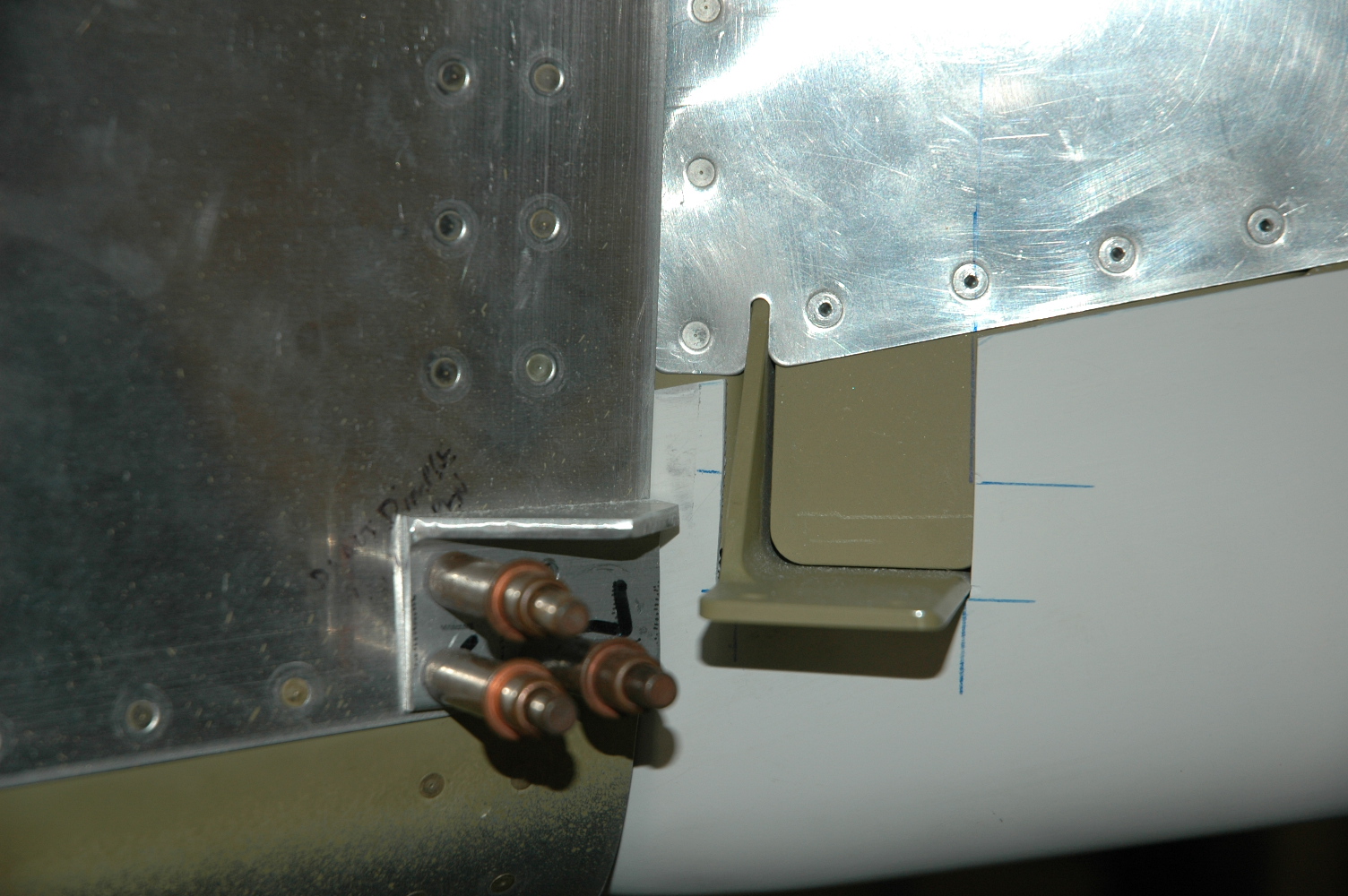
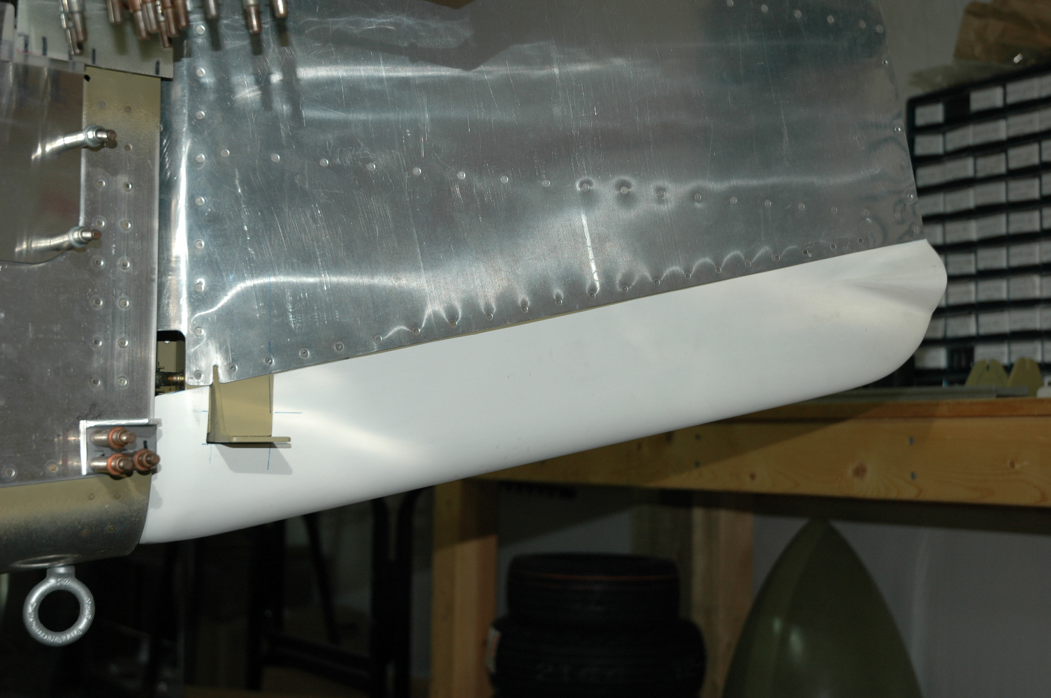
Trimmed the rudder bottom to allow it to insert onto the rudder and clear the rudder horn. The rudder was too low by about 5/8" compared to how it looks on the drawing, so I trimmed about that much from the top edges, refitted it and it looks better. It scraps against the fuse when the rudder is moved to full left and right range, so I'll have to figure out how to fix this. Fly-in is this weekend so I will take some pictures of rudders there for reference.
|
|
|
2006-03-21 |
Hours: 2 |
Category:
Empennage
|
|
Manual Ref:
|
ID#:
893
|
|
Rudder tail light installation |
|
Worked on the aft end of the rudder bottom to get the tail light installed. Drilled the big hole about 1 1/16" dia. I used a 1" hole saw then the Dremel to open it up large enough to insert the light. I rolled up a piece of index card paper like a paper towel roll, inserted it into the large hole about 1/2". From the inside I injected epoxy/flox around the outside of the paper tube to make a thicker surface to work with for the mounting screws/nuts. Let this set up for several hours. Positioned and drilled pilot holes for the screws and inserted the screws and let this set up overnight.
|
|
|
2006-03-14 |
Hours: 1.5 |
Category:
Empennage
|
|
Manual Ref:
|
ID#:
882
|
|
Rudder and VS top fiberglass tips |
|
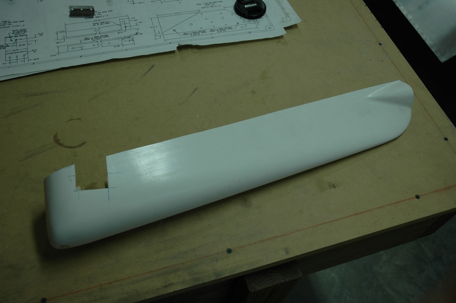
Worked on the rudder and VS top fiberglass tips. Installed the rudder tip and cut the aft edges of the VS tip. It fits well, so I am ready to glass the aft side. Started on the emp fairing too by incrementally cutting the lower aft part that goes around the elevator horns. Cut some, test fit, cut some more.
|
|
|
2003-07-19 |
Hours: 1 |
Category:
Empennage
|
|
Manual Ref:
|
ID#:
381
|
|
Worked on the elevator fiberglass tips |
|
Trimmed the excess off the elevator fiberglass tips and test fitted. Not much else to do but get a wing kit!
|
|
|
2003-07-19 |
Hours: 0.5 |
Category:
Empennage
|
|
Manual Ref:
|
ID#:
380
|
|
Test fitted the rudder to the VS |
|
Put eye bolt bearings in the rudder and test fitted to the VS.
|
|
|
2003-07-18 |
Hours: 1 |
Category:
Empennage
|
|
Manual Ref:
6-10
|
ID#:
378
|
|
More work with the elevators and HS |
|
Removed elevators from HS and adjusted bearing bolts. Measured dist. From spar to bearing bold center by placing 3/16" steel round thru holes and measuring from the center.
|
|
|
2003-07-14 |
Hours: 2 |
Category:
Empennage
|
|
Manual Ref:
6-10
|
ID#:
377
|
|
Test fitted the elevators on the HS |
|
Mounted the elevators on the HS. Put the bearing bolts in at 7/8" or one more half turn. Have approx. 25 degrees upward movement and 25-28 degrees downward.
|
|
|
2003-07-12 |
Hours: 3 |
Category:
Empennage
|
|
Manual Ref:
6-10
|
ID#:
376
|
|
Worked with the elevator counterbalance weights |
|
Cut the lead weights and fitted to the elevators. Had to removed them a couple of times and trim more lead off. At first, I thought I'd leave more lead to counterbalance paint, etc. but it seems obviouse that has been taken into account. On hind sight, I'd wait until the emp is attached to the fuse before messing with the weights. There is no reason to try and get them balanced at this point.
|
|
|
2003-07-12 |
Hours: 2.5 |
Category:
Empennage
|
|
Manual Ref:
6-9
|
ID#:
375
|
|
Finished attaching the trim tab to the left elevator |
|
Formed a piece of block nylon that EAA Tech Rep. Ken Harrill lent me to make a bending tool for the trim tab skin. Got the lower trim tab skin bent nicely. Riveted the piano hinge to the trim tab and elevator trim spar.
|
|
|
2003-07-11 |
Hours: 3 |
Category:
Empennage
|
|
Manual Ref:
6-9
|
ID#:
401
|
|
More work on the trim tab |
|
Drilled hinge to the elevator trim tab spar. Not really happy with the results. Just a bit crooked. Took the elevator/trim tab to Owens Field to see if some EAAers were hanging around. EAA Tech Rep Ken Harrill was there. He looked at my work and suggested how to bend the lower trim tab skin to allow it to clear the spar. He lent me a piece of nylon block to use to make a "skin bender". I made several passes with the skin bender tool, sliding it the length of the skin and bending the skin a little bit more with each pass. Resulted in a nice bend. I removed the hinge piece that was clecoed to the elevator trim tab spar and replaced it with a new piece (leftover). This one is straighter along the length and has a bit more gap on the outboard end for clearance of the elevator.
|
|
|
2003-07-05 |
Hours: 2.5 |
Category:
Empennage
|
|
Manual Ref:
6-9
|
ID#:
371
|
|
Riveted the trim tab spar bottom flange to the trim tab skin. I back riveted with the steel plate. I very carefully bent the top skin up just enough to get the rivet gun into place. ProSealed the foam wedges, inserted, clecoed and riveted the upper flange, skin, and hinge. Also put the pop rivets in the ends. Place assembly into the wood clamps.
|
|
|
2003-07-03 |
Hours: 2.5 |
Category:
Empennage
|
|
Manual Ref:
6-9
|
ID#:
370
|
|
Prepped all trim tab parts for priming |
|
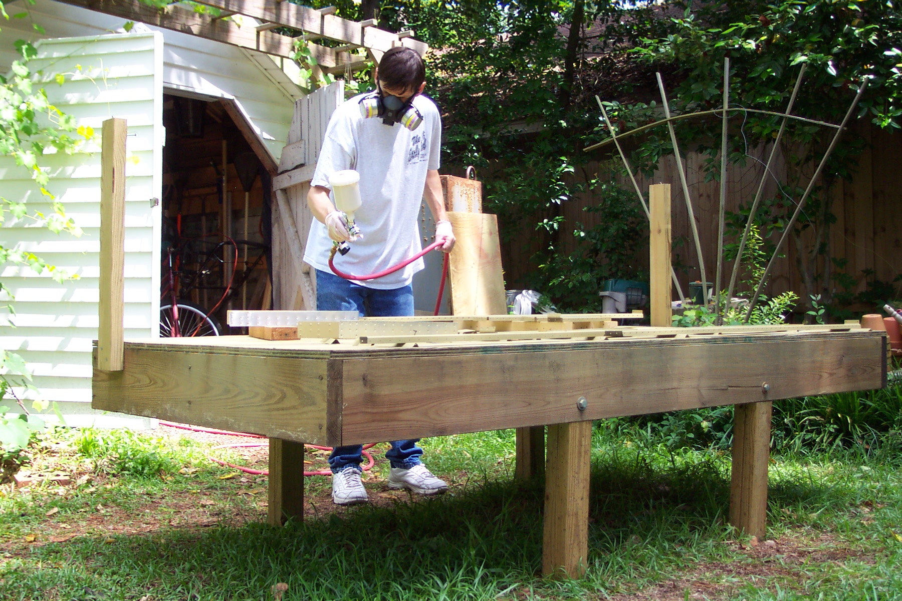
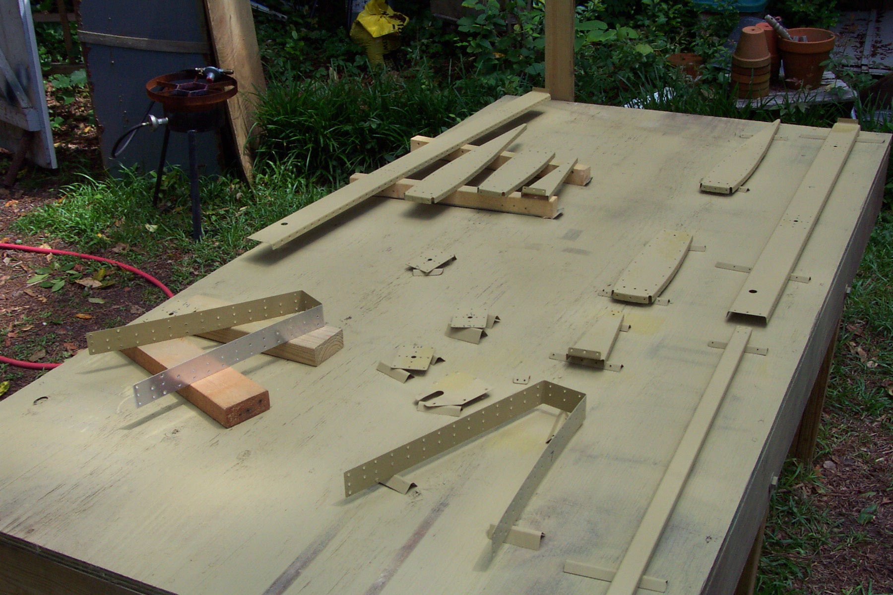
Cleaned all trim tab parts and prepped with Du Pont 225. Primed all trim tab parts. Ready to assemble.
|
|
|
2003-07-02 |
Hours: 0.5 |
Category:
Empennage
|
|
Manual Ref:
6-9
|
ID#:
368
|
|
Got new trim tab hinge from Vans. |
|
Got the new hinge for the trim tab; match drilled to the spar flange. Looks better this time!
|
|
|
2003-06-23 |
Hours: 0.25 |
Category:
Empennage
|
|
Manual Ref:
6-9
|
ID#:
367
|
|
Order a new trim tab piano hinge |
|
Ordered a new piano hinge for the trim tab. I am not happy with the job I did drilling the first one. The hinge needs to be set just a little bit more up under the trim tab spar flange to reduce the gap when installed on the elevator.
|
|
|
2003-06-18 |
Hours: 1.75 |
Category:
Empennage
|
|
Manual Ref:
6-9
|
ID#:
366
|
|
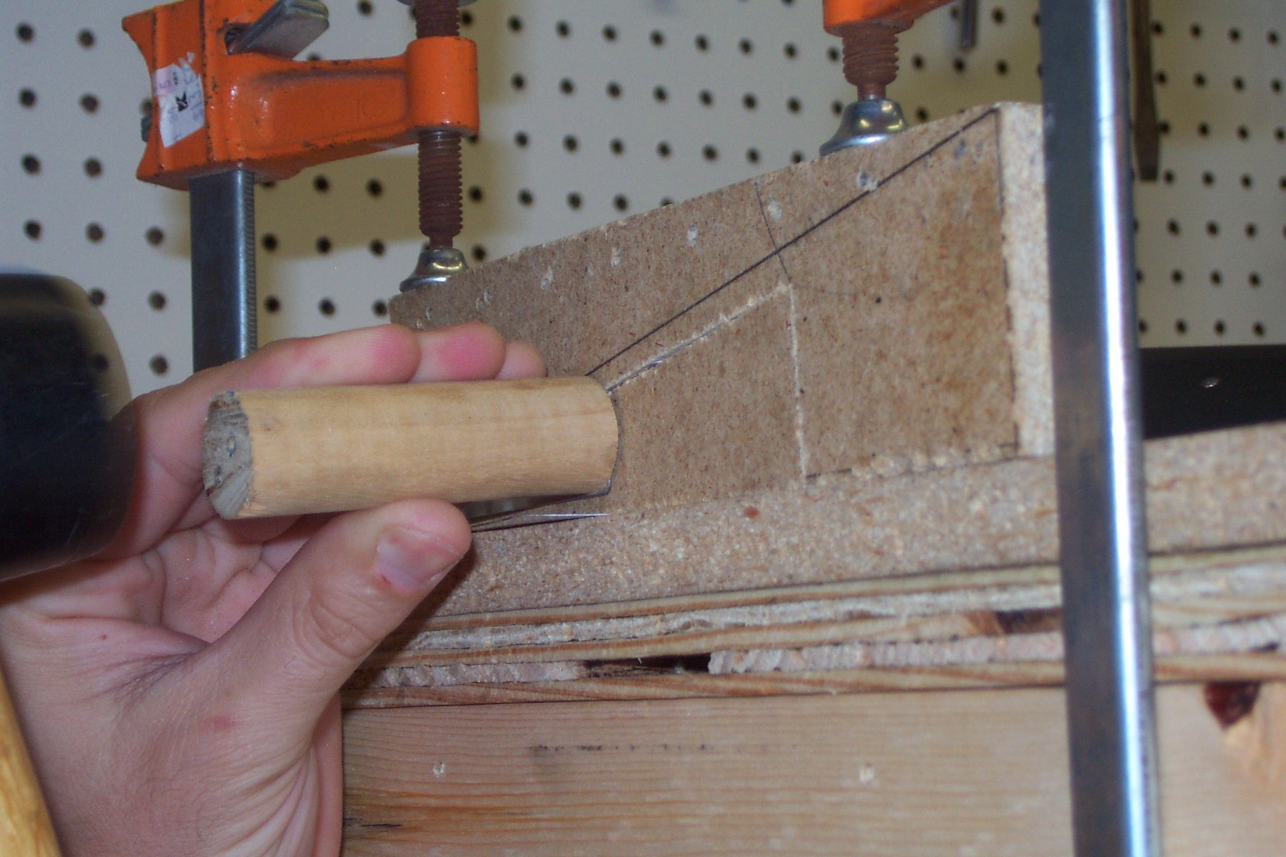
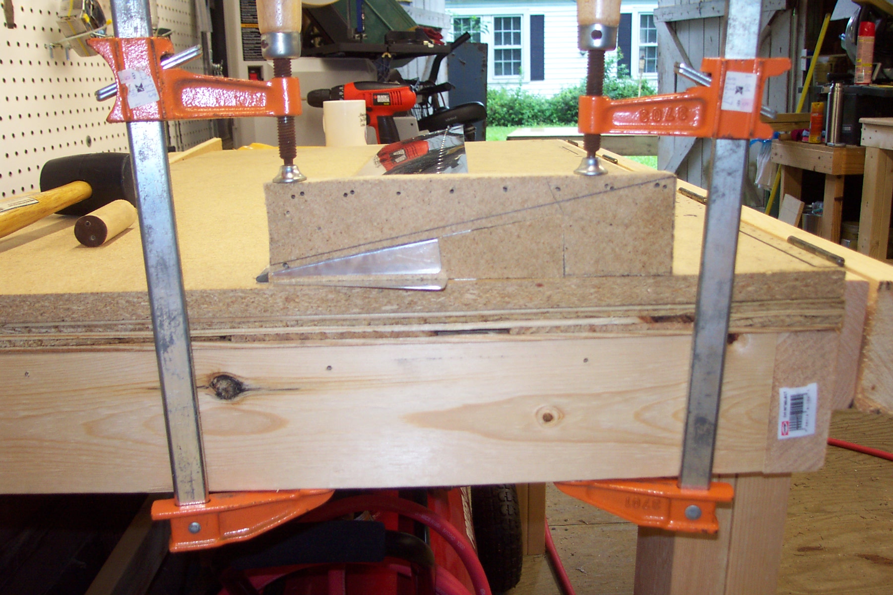
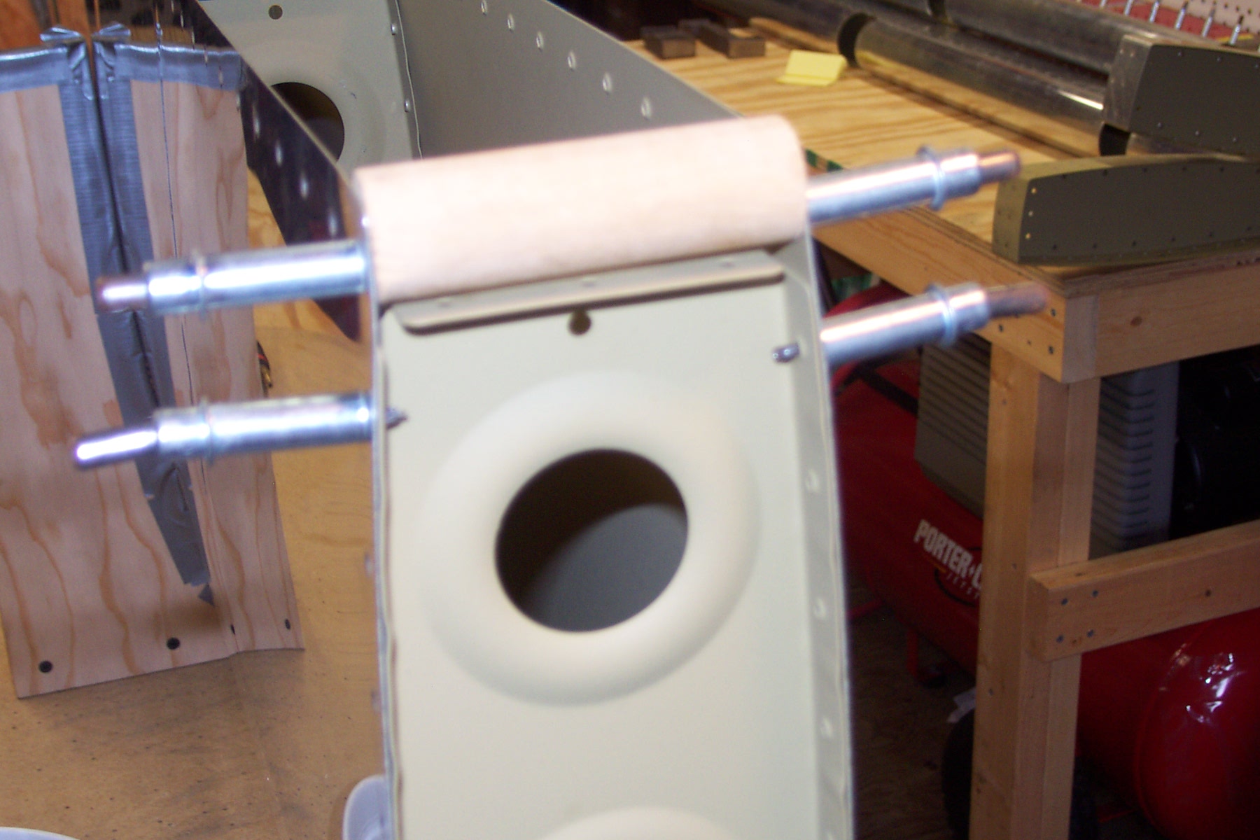
Success with the trim tab! |
|
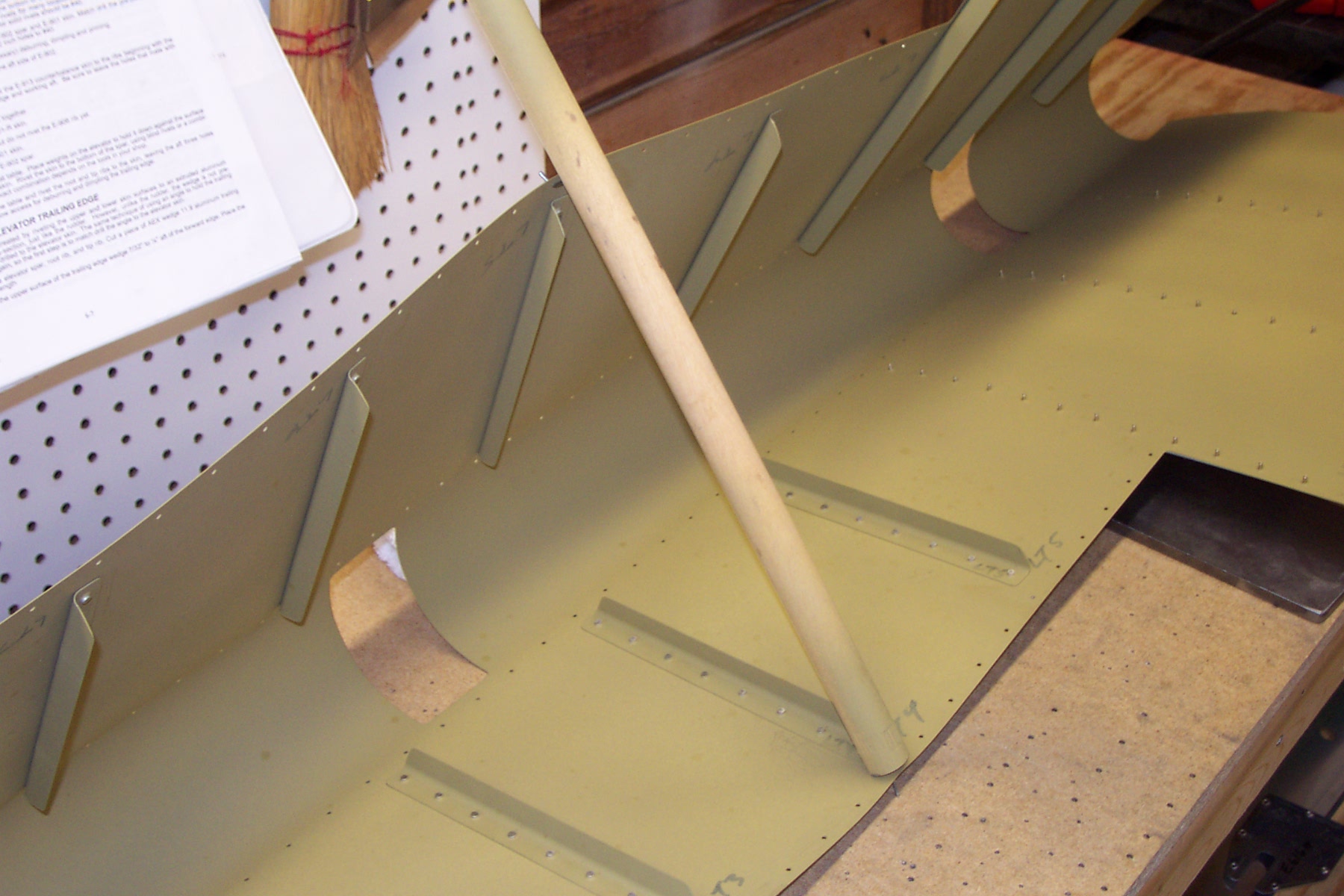
Bent the ends of the trim tab per Van's instructions. Instead of using the mushroom rivet set on the rivet gun, I used a 4 inch length of 1 inch diameter wood dowel and a rubber mallet. Looks good! Stick to Van's suggested method.
|
|
|
2003-06-17 |
Hours: 2.5 |
Category:
Empennage
|
|
Manual Ref:
6-9
|
ID#:
365
|
|
More work on the trim tab |
|
Countersunk the upper part of the trim tab spar. Tried to bend the bottem outboard end of the trim tab but was not happy with the results. The rivet gun with the mushroom set is too powerful. I bent the end back flat. Will try again tomorrow.
|
|
|
2003-06-16 |
Hours: 2.25 |
Category:
Empennage
|
|
Manual Ref:
6-9
|
ID#:
361
|
|
Began work on my trim tab |
|
Tinkered with the trim tab parts a bit. Drilled the new trim tab skin to the spar. Ordered new parts E-9117 & 918. The ones I have don't seem to want to lay flat against the skin. Perhaps prior riveting and removing from the old skin warped them slightly. Match drilled the hinge to the trim spar. Need to order more 3-4 rivets.
|
|
|
2003-06-15 |
Hours: 4 |
Category:
Empennage
|
|
Manual Ref:
6-2
|
ID#:
360
|
|
Still more work on the HS |
|
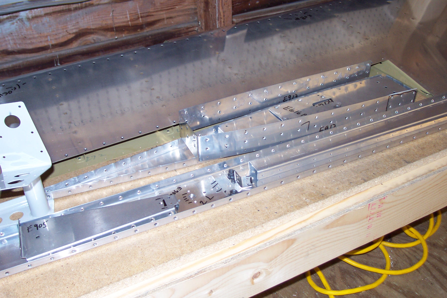
Bolted the HS-911 hinge bracket onto the HS rear spar. Had to drill out the four holes to 3/16. Finished riveting end and center main ribs to rear spar. Finished riveting skin to rear spar. I need 6 LP4-3 rivets to finish the HS assembly; these rivets are for the left main rib to rear spar, 3 each.
|
|
|
2003-06-14 |
Hours: 4.5 |
Category:
Empennage
|
|
Manual Ref:
6-2
|
ID#:
359
|
|
Assembled the HS-911 hinge bracket: drilled, riveted. Riveted HS main ribs to spar and skin. Riveted some skin to rear spar rivets.
|
|
|
2003-06-13 |
Hours: 4.75 |
Category:
Empennage
|
|
Manual Ref:
6-2
|
ID#:
358
|
|
Did some more HS riveting |
|
Riveted nose ribs into HS skin. This was not fun the second time either. Riveted the HS skin to the forward spar.
|
|
|
2003-06-10 |
Hours: 1 |
Category:
Empennage
|
|
Manual Ref:
6-2
|
ID#:
357
|
|
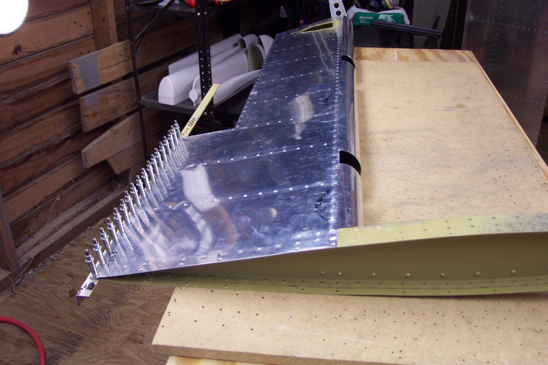
Started riveting the right HS |
|
This evening, I started on the right HS. Got the skin into the jig and clecoed the nose ribs into place.
|
|
|
2003-06-10 |
Hours: 1 |
Category:
Empennage
|
|
Manual Ref:
6-2
|
ID#:
356
|
|
Finished riveting the HS left skin to main ribs. |
|
This morning, I riveted the left HS main ribs to the bottom skin.
|
|
|
2003-06-09 |
Hours: 0.5 |
Category:
Empennage
|
|
Manual Ref:
6-2
|
ID#:
354
|
|
Squeezed a little work in today |
|
Got one side of a HS rib riveted in.
|
|
|
2003-06-08 |
Hours: 6 |
Category:
Empennage
|
|
Manual Ref:
6-2
|
ID#:
353
|
|
Started assembling the horizontal stabilizer |
|
Assembled some of the left HS. Riveted in the 3 nose ribs, riveted all but the outboard main rib to the spar and riveted the skin to the front spar. This was not fun.
|
|
|
2003-06-07 |
Hours: 1 |
Category:
Empennage
|
|
Manual Ref:
6-2
|
ID#:
351
|
|
Riveted the HS forward spars/doubler |
|
Riveted the HS forward spars, doubler and attach angles together. I had a smiley on the head of two rivets on one of the attach angles. I removed 1 and drilled the hole bigger so I had to order some 4-10's from Aircraft Spruce. Ugh.
|
|
|
2003-06-06 |
Hours: 3.5 |
Category:
Empennage
|
|
Manual Ref:
6-3
|
ID#:
350
|
|
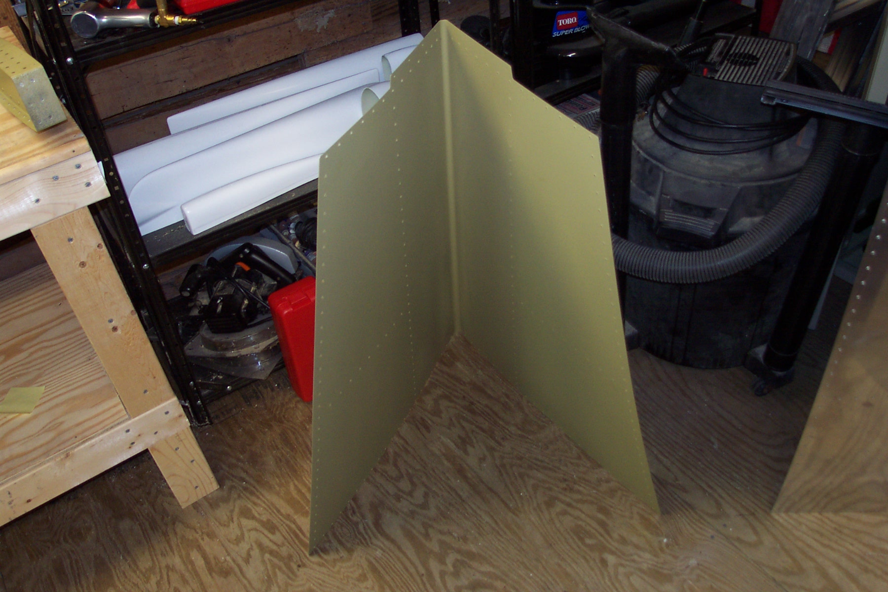
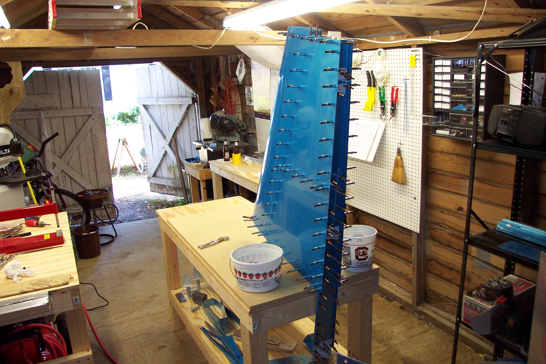
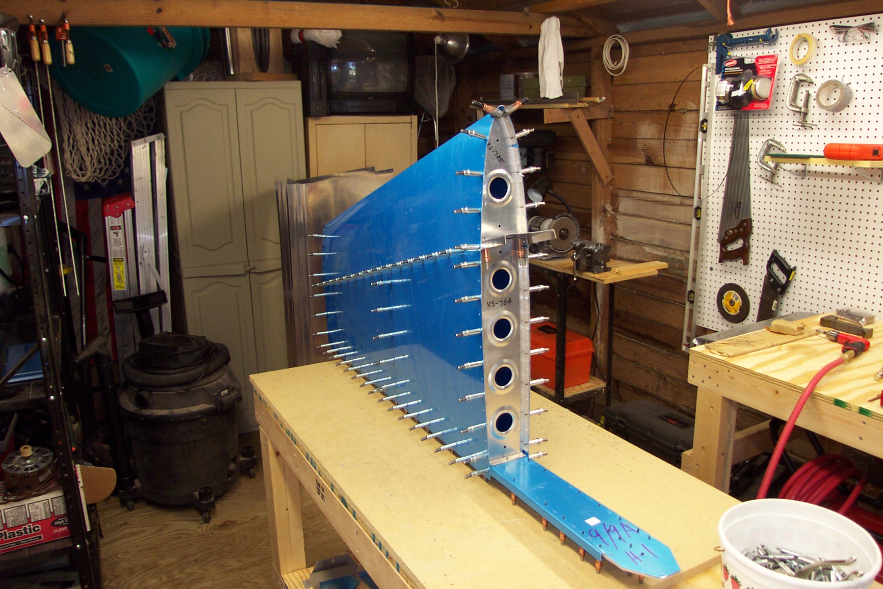
Assembled the vertical stabilizer |
|
Assembled the VS; Two rivets on each side of the skin/rear spar at the VS-411's were difficult because of interferring rivet heads in the doubler. Hard place to squeeze rivets.
|
|
|
2003-06-05 |
Hours: 3.2 |
Category:
Empennage
|
|
Manual Ref:
6-2
|
ID#:
349
|
|
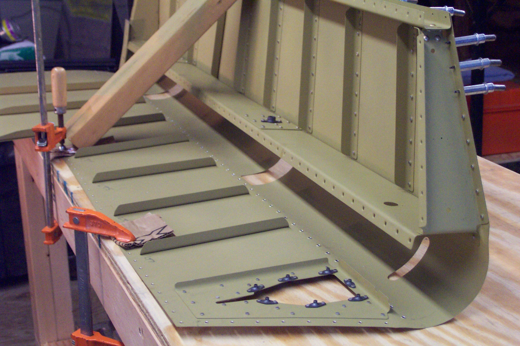
Primed the HS frame parts and inside skins. |
|
Primed the HS frame parts and inside skins.
|
|
|
2003-06-04 |
Hours: 2 |
Category:
Empennage
|
|
Manual Ref:
6-3
|
ID#:
348
|
|
Primed the VS frame parts and inside skin. |
|
Primed the VS frame parts and inside skin.
|
|
|
2003-06-03 |
Hours: 1 |
Category:
Empennage
|
|
Manual Ref:
6-9
|
ID#:
347
|
|
Riveted right elevator trailing edge |
|
Riveted the trailing edge on right elevator and filed the trailing edge down to 1/32" per the drawings.
|
|
|
2003-06-02 |
Hours: 5.5 |
Category:
Empennage
|
|
Manual Ref:
6-2
|
ID#:
346
|
|
Prepped VS and HS parts for priming |
|
Washed all VS and HS parts with dish detergent and wiped down with laquer thinner. Some parts seemed to have a film residue so I used Du Pont 225 on the skins and spars and doublers. Also on the angle attach brackets.
|
|
|
2003-06-01 |
Hours: 3.2 |
Category:
Empennage
|
|
Manual Ref:
6-8
|
ID#:
345
|
|
Prosealed right elevator TE and back riveted the left elevator TE |
|
Riveted the last few rivets on the tip and roots ribs of the right elevator. Applied ProSeal to the trailing edge and clecoed with the Aluminum angle attached. Back riveted the trailing edge of the left elevator & riveted remaining tip to skin rivets.
|
|
|
2003-05-30 |
Hours: 7 |
Category:
Empennage
|
|
Manual Ref:
6-7
|
ID#:
343
|
|
Riveted the right elevator |
|
Built the right elevator. Riveted the frame together. Riveted horn to spar/rib assembly. Riveted the top skin to spar, bottom skin to spar. Tip and root ribs to skin. Drilled/deburred/dimpled and countersunk the trailing edge.
|
|
|
2003-05-30 |
Hours: 3 |
Category:
Empennage
|
|
Manual Ref:
6-9
|
ID#:
339
|
|
Worked on the trim tab and screwed it up trying the bend the ends. Had to order a new one from Van's.
|
|
|
2003-05-29 |
Hours: 8.5 |
Category:
Empennage
|
|
Manual Ref:
6-9
|
ID#:
342
|
|
Worked all day on riveting the left elevator skin to the frame |
|
I worked all day riveting the left elevator skin to the frame. Also, drilled the trailing edge and set up with ProSeal per instructions.
|
|
|
2003-05-26 |
Hours: 2.5 |
Category:
Empennage
|
|
Manual Ref:
6-8
|
ID#:
334
|
|
Assembled the left elevator frame |
|
Riveted the left elevator frame parts and riveted the skin to the top of the spar and the tip ribs.
|
|
|
2003-05-25 |
Hours: 2 |
Category:
Empennage
|
|
Manual Ref:
6-8
|
ID#:
332
|
|
Primed the left and right elevator parts.
|
|
|
2003-05-24 |
Hours: 2 |
Category:
Empennage
|
|
Manual Ref:
6-7
|
ID#:
330
|
|
Washed elevator parts for priming |
|
Washed left and right elevators parts to get ready to prime them.
|
|
|
2003-05-23 |
Hours: 2.5 |
Category:
Empennage
|
|
Manual Ref:
6-7
|
ID#:
328
|
|
Drilled and dimpled the right elevator |
|
Drilled all holes except trailing edge and dimpled the right elevator frame and skins. Ready for priming.
|
|
|
2003-05-23 |
Hours: 1 |
Category:
Empennage
|
|
Manual Ref:
6-7
|
ID#:
325
|
|
Clecoed the right elevator together, ready for drilling |
|
Clecoed the right elevator frame and skin together and match drilled all the holes not yet done.
|
|
|
2003-05-22 |
Hours: 2.5 |
Category:
Empennage
|
|
Manual Ref:
6-8
|
ID#:
323
|
|
Dimpled all left elevator parts |
|
Left elevator is ready to prime and assemble.
|
|
|
2003-05-21 |
Hours: 1.5 |
Category:
Empennage
|
|
Manual Ref:
6-8
|
ID#:
321
|
|
Assembled and matched drilled the left elevator |
|
Clecoed the left elevator frame and skin together and match drilled all the skin holes and frame holes not yet drilled.
|
|
|
2003-05-20 |
Hours: 2.5 |
Category:
Empennage
|
|
Manual Ref:
6-8
|
ID#:
319
|
|
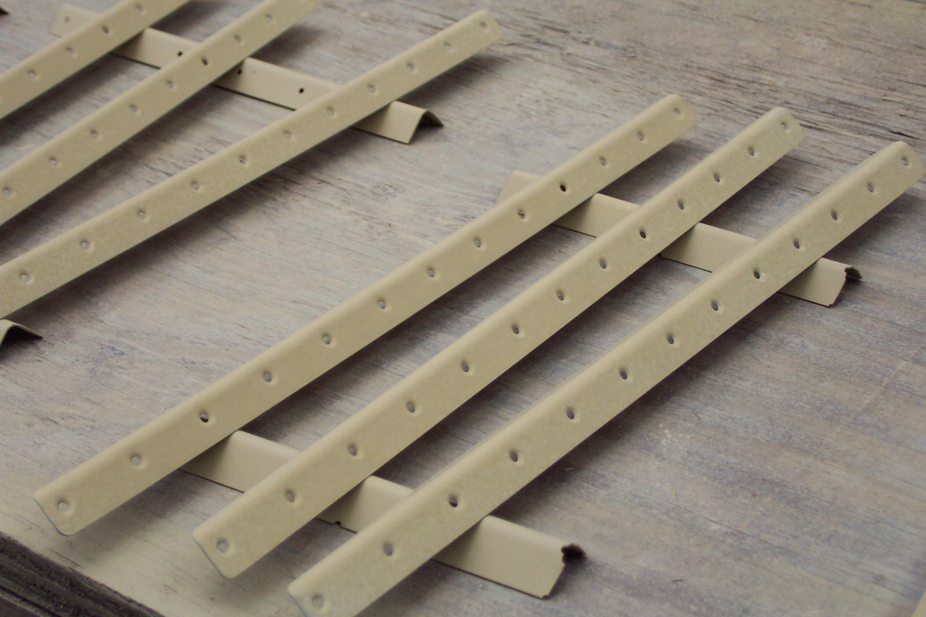
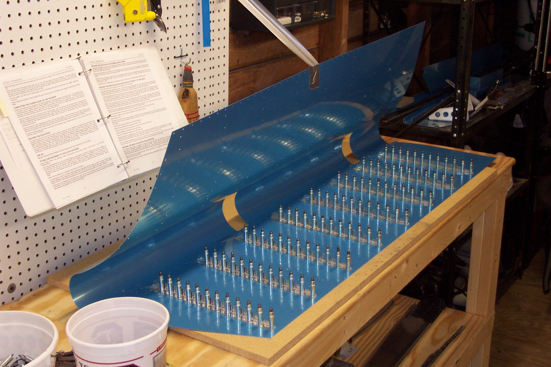
Riveted the stiffeners in the left elevator skins |
|
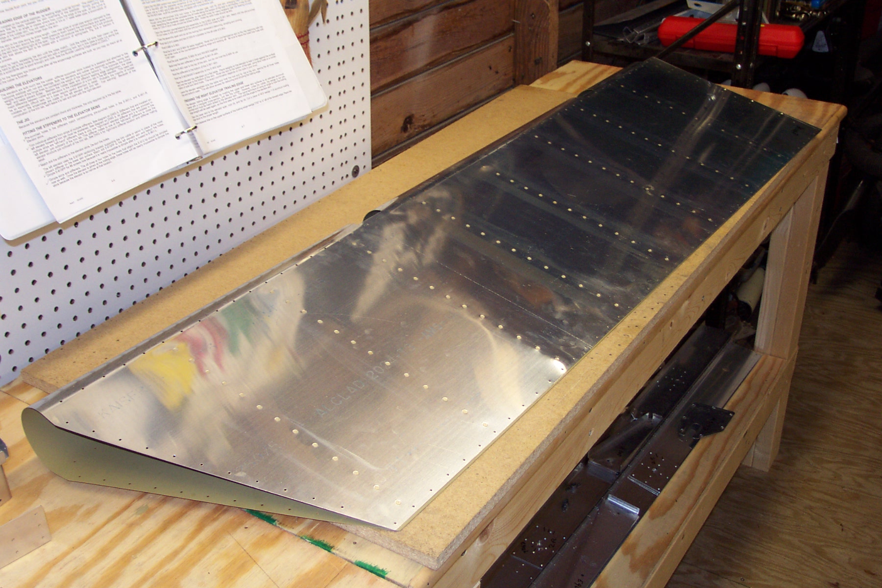
Riveted all the stiffeners in the elevators skins. I used -3.5 rivets instead of the -3's that Van's called out because when i riveted the stiffeners into the rudder, many of the rivets looked too flat, although not extremely flat. Van's said this will be okay.
|
|
|
2003-05-19 |
Hours: 0.5 |
Category:
Empennage
|
|
Manual Ref:
6-8
|
ID#:
317
|
|
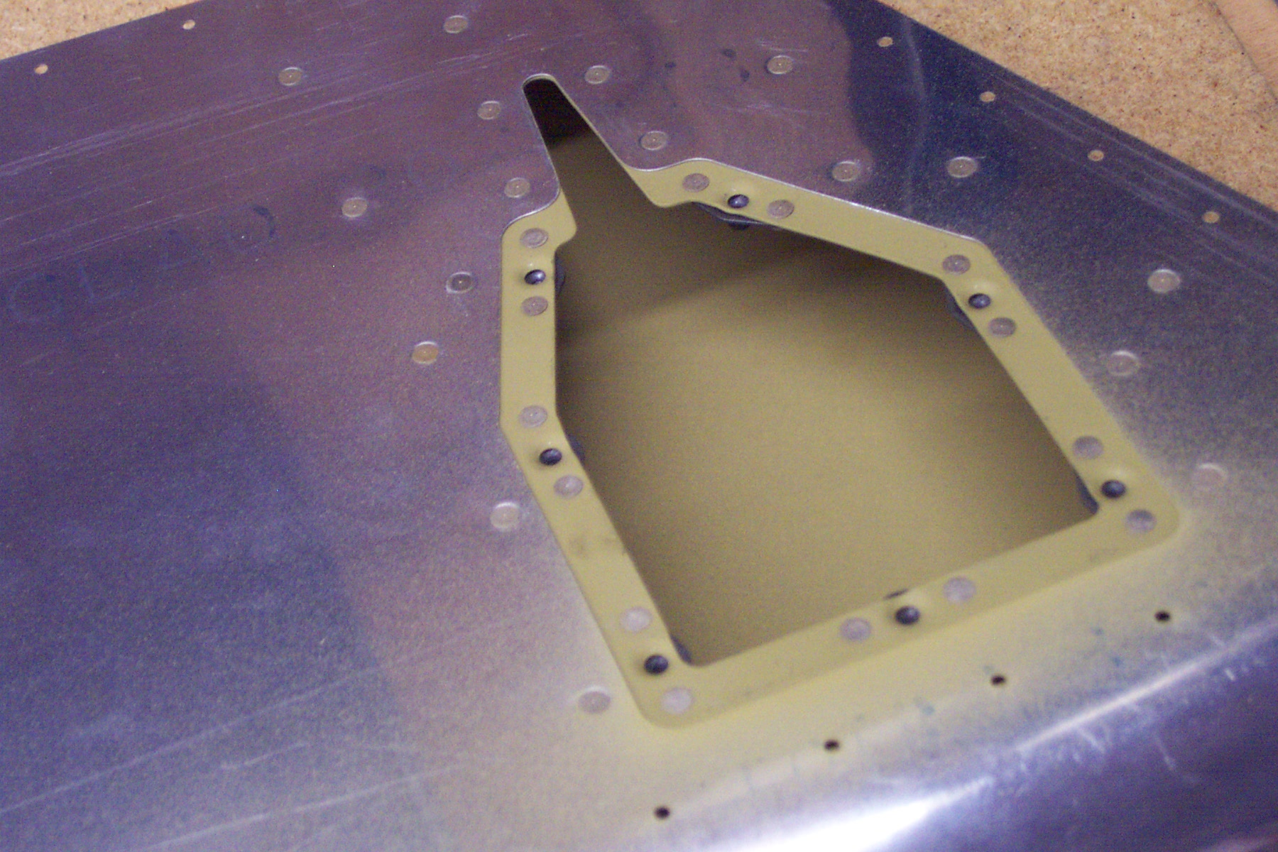
Riveted the trim access reinforcing plate |
|
Riveted the E-615PP trim access reinforcing plate to the elevator skin. Before this I riveted the 5 platenuts to the E-615PP.
|
|
|
2003-05-18 |
Hours: 2.5 |
Category:
Empennage
|
|
Manual Ref:
6-6
|
ID#:
315
|
|
Primed elevator skins and stiffeners |
|
Primed the elevator skins and stiffeners. Hope to be doing some more riveting tomorrow.
|
|
|
2003-05-17 |
Hours: 1.75 |
Category:
Empennage
|
|
Manual Ref:
6-7
|
ID#:
312
|
|
Prepped the elevator skins and stiffeners for priming |
|
Washed the elevator skins and stiffeners with dish detergent and wiped down with laquer thinner. They are ready to prime.
|
|
|
2003-05-17 |
Hours: 1 |
Category:
Empennage
|
|
Manual Ref:
6-5
|
ID#:
306
|
|
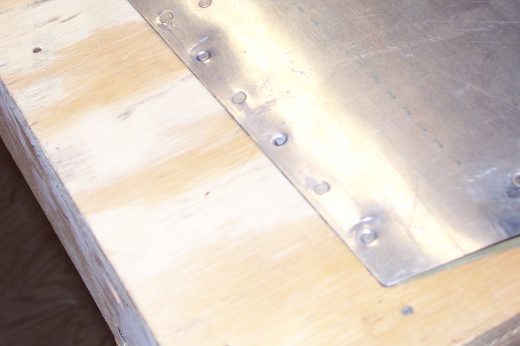
Riveted the trailing edge of the rudder |
|
Riveted the trailing edge of the rudder. Came out nice and straight. A few smilies but otherwise nice work. I riveted with the back rivet set. In hind sight, I'd use the back rivet set to start the rivets, then turn the rudder over and use the flush set to finish the rivets.
|
|
|
2003-05-15 |
Hours: 1.1 |
Category:
Empennage
|
|
Manual Ref:
|
ID#:
159
|
|
Applied ProSeal to trailing edge and clecoed to aluminum angle to cure. |
|
Mixed about 70 grams of proseal and buttered up the trailing edge of the rudder and clecoed into place. Now, hurry up and wait.
|
|
|
2003-05-15 |
Hours: 0.7 |
Category:
Empennage
|
|
Manual Ref:
|
ID#:
158
|
|
Finished curling rudder leading edge and riveted. |
|
Finished curling rudder leading edge and riveted. Did center portion this morning
|
|
|
2003-05-14 |
Hours: 1.5 |
Category:
Empennage
|
|
Manual Ref:
|
ID#:
157
|
|
Curled the upper and lower leading edge skin sections. |
|
Curled the upper and lower section of the rudder leading edge and riveted.
|
|
|
2003-05-14 |
Hours: 4 |
Category:
Empennage
|
|
Manual Ref:
|
ID#:
156
|
|
Riveted tight ends of rudder ribs to skins |
|
Riveted tight ends of rudder ribs to skins.
|
|
|
2003-05-13 |
Hours: 10 |
Category:
Empennage
|
|
Manual Ref:
6-5
|
ID#:
304
|
|
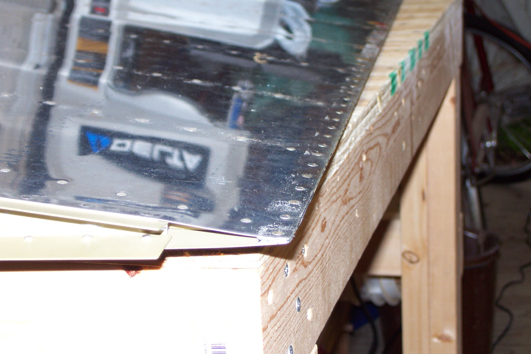
Started riveting the rudder together |
|
Riveted the rudder frame parts and skins on the rudder today. Next is the trailing edge and proseal!
|
|
|
2003-05-12 |
Hours: 2 |
Category:
Empennage
|
|
Manual Ref:
6-4
|
ID#:
301
|
|
Primed the rudder frame parts |
|
Got the rudder frame parts all primed and ready for final assembly.
|
|
|
2003-05-09 |
Hours: 2 |
Category:
Empennage
|
|
Manual Ref:
6-4
|
ID#:
299
|
|
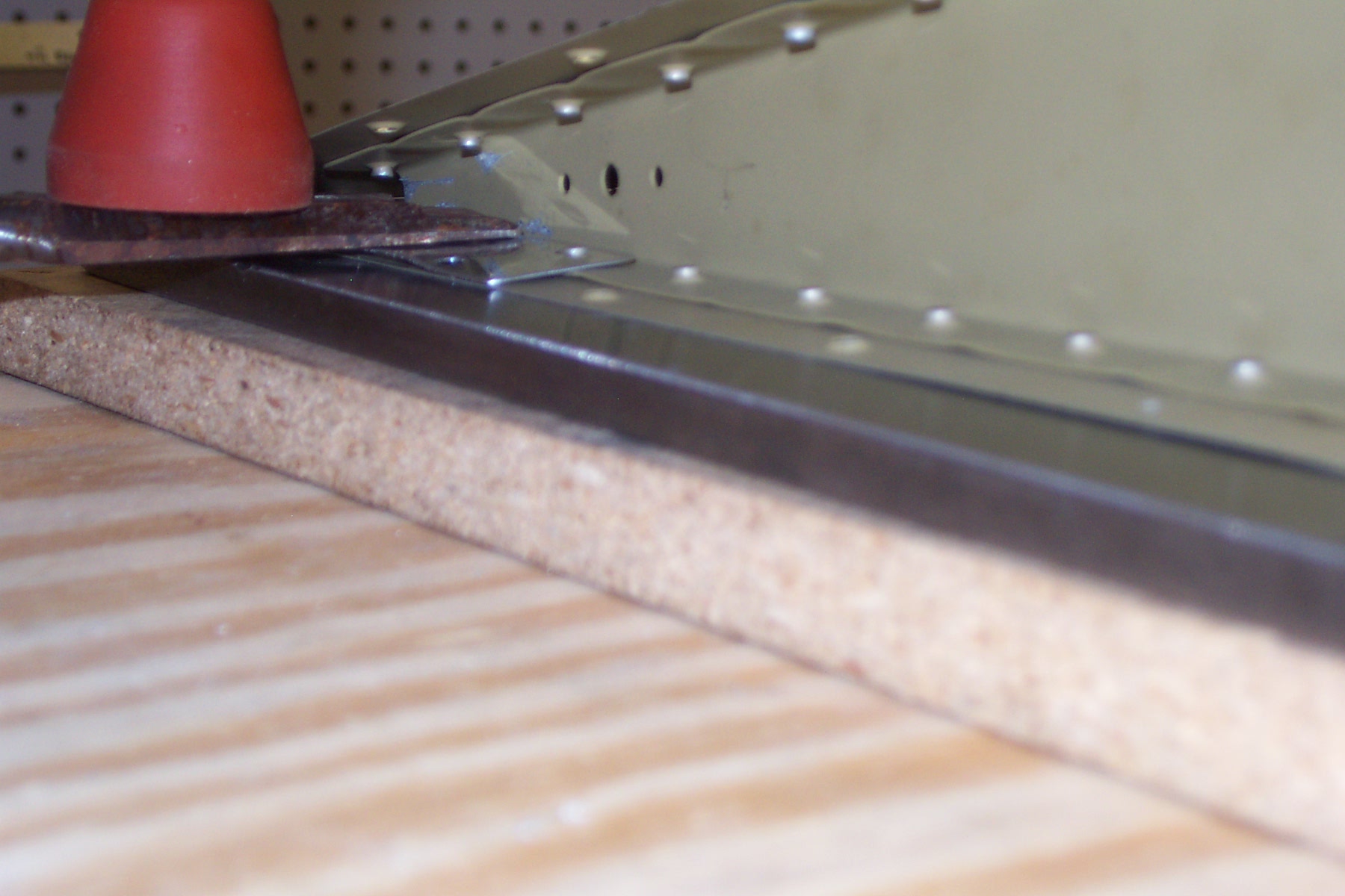
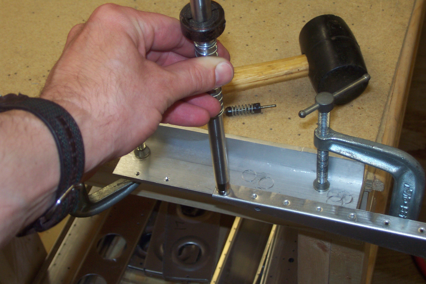
Dimpled the tight ends of the rudder ribs. |
|
Had difficulty trying to figure out how to dimple the tight end of the rudder ribs. After consulting the newsgroup at Yahoo and scratching my head, I finally figured out what to do. Luckily I had a piece of solid angle left over from when I had to re-order a piece because I goofed up my first set of HS attach angles. I countersunk the angle near enough to the edge so that working with the ribs would be okay. The countersink is a little deeper than the rivet head so when a rivet is inserted into the countersink it is not flush with the angle surface. It is another turn on the microstop deeper. I clamped the angle to the edge of my table. I didn't permanently attached the particle board I use for drilling, so I could just slide it over the edge of the table enough to clamp it and the angle. I then just slid the rudder rib in there and lined up the hole in the rib with the countersink and used the driver shaft from the hand riveting and dimpling tool with the 3/32 male dimple die and pounded away. It took a few good wacks to set the dimple and the results are okay. The dimple is not as "pretty" as you might be used to with the hand dimpler or even the vise grip or rivet dimplers but the head of the rivet settles in good enough.
|
|
|
2003-05-07 |
Hours: 2 |
Category:
Empennage
|
|
Manual Ref:
6-4
|
ID#:
300
|
|
Clecoed the rudder together and drilled the trailing edge |
|
I match drilled the aluminum angle to the trailing edge. All drilled and clecoed together, the trailing edge looks pretty darned straight. Can't wait to make a mess with the proseal.
|
|
|
2003-05-05 |
Hours: 3 |
Category:
Empennage
|
|
Manual Ref:
6-4
|
ID#:
297
|
|
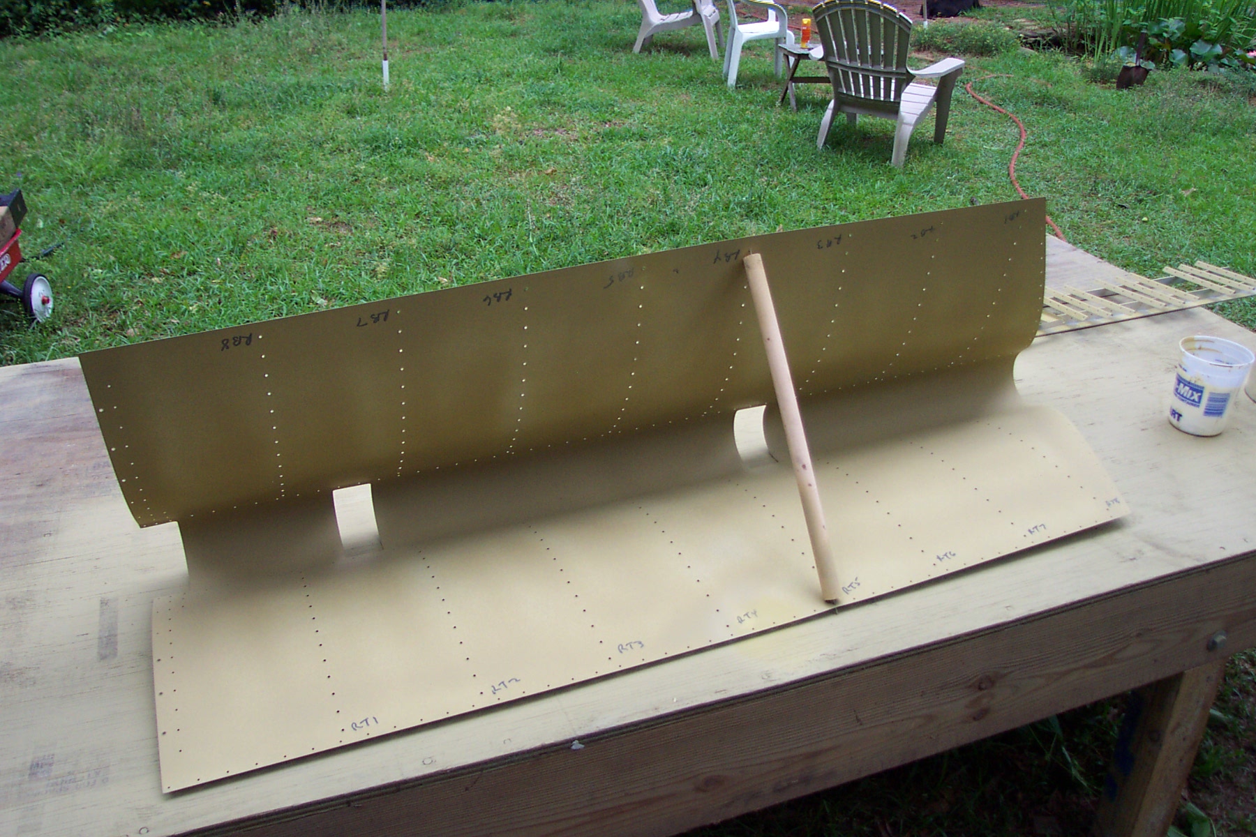
Primed the inside of the rudder skins |
|
Primed the inside of the rudder skins and clecoed the rudder together.
|
|
|
2003-04-27 |
Hours: 2 |
Category:
Empennage
|
|
Manual Ref:
6-7
|
ID#:
293
|
|
Fabricated the E-921 gusset, clecoed to elevator frame |
|
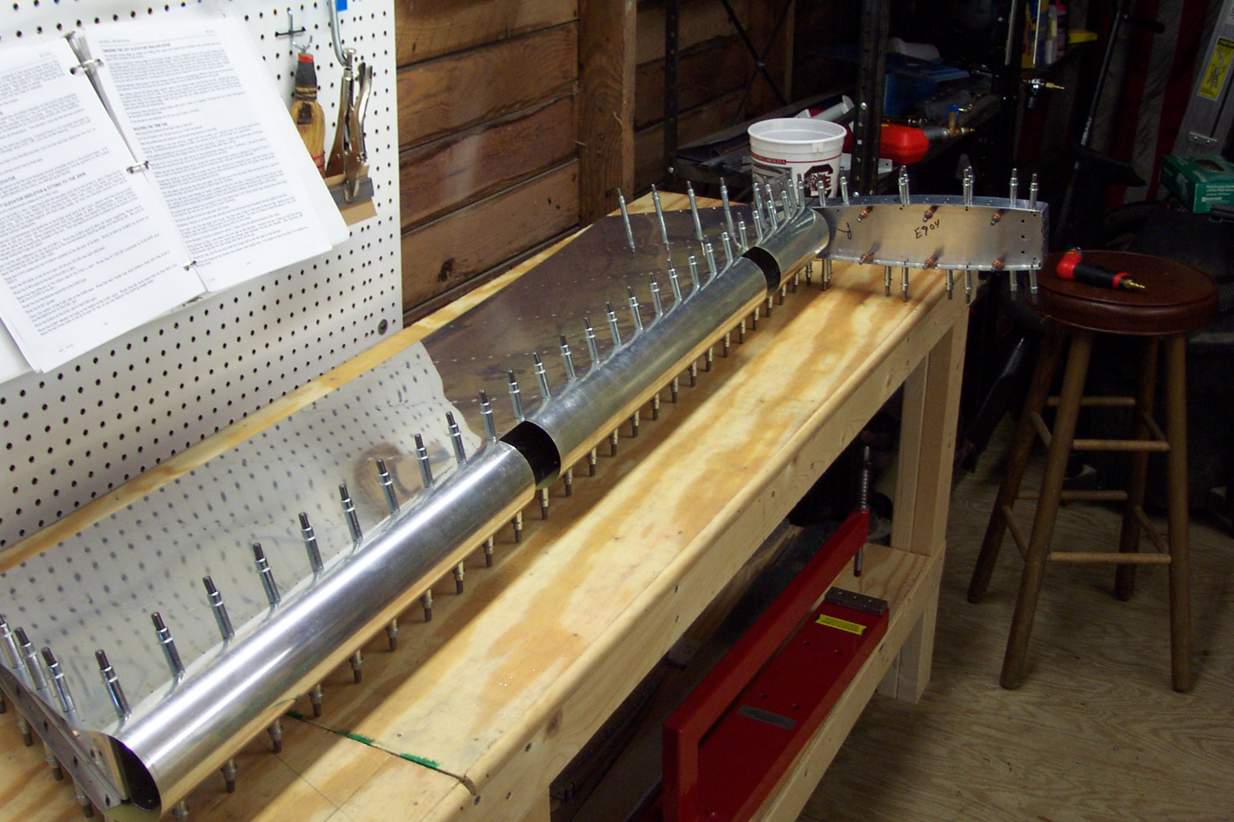
I fabricated the E-921 Gusset after three other tries. This was actually quite a challenge. I cut the piece to specs and bent with the hand seamers up against the table top. You have to be careful and apply even pressure left and right to make sure you get a good bend that is the same at both ends of the gusset. Clamp the flat gusset into the hand seamers so that you can barely see any of the center "bend" line on the gusset. This will make the bend right on the line. I had to find this out the hard way - trial and error. Attached the E-921 Gusset to the Left Elevator frame components. I clecoed the skin onto the frame about 12 holes from the end - offset, so to speak, so the rear spar and front spar are held in actual conditions so I could get the gusset attached accurately. Seemed to work just fine. Make sure you have the skin clecoed correctly so the angle at the gusset joint is correct. I drilled and clecoed the E-921 Gusset into place. All but one of the hole were drilled before hand. The plans are kinda vague on this.
|
|
|
2003-04-21 |
Hours: 2.5 |
Category:
Empennage
|
|
Manual Ref:
6-7
|
ID#:
292
|
|
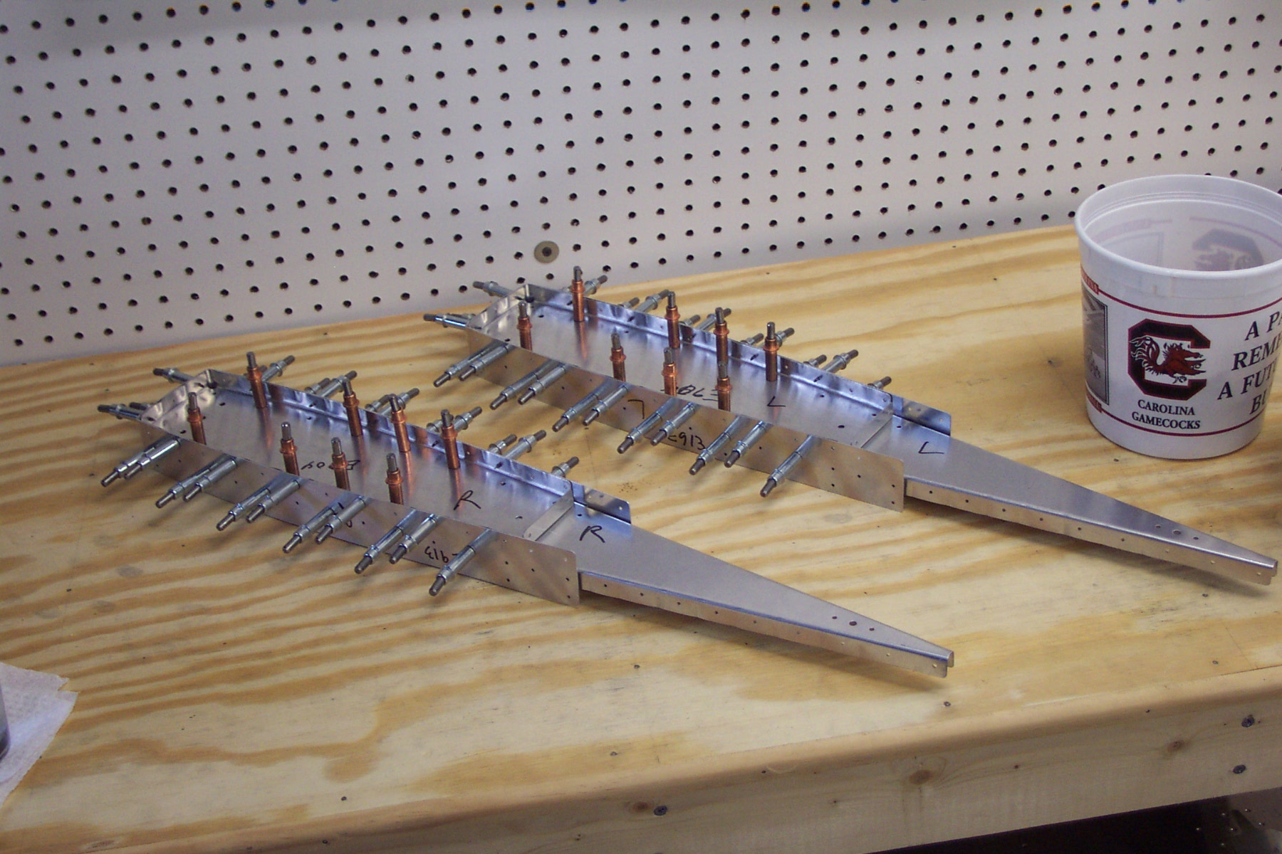
Assembled the elevator counter balance arms |
|
Today I clecoed and drilled the he elevator counter balance arms. They kinda look like a pair of ancient critters or something. You think at first that the counterbalance skin will never fit but it does with amazing accuracy. You might have to nudge it a little, but don't overdo it. A litttle finesse gets them together quite easily. You might have to kind of twist the ribs a little but the skins fit like a glove.
|
|
|
2003-03-30 |
Hours: 2.5 |
Category:
Empennage
|
|
Manual Ref:
6-6
|
ID#:
290
|
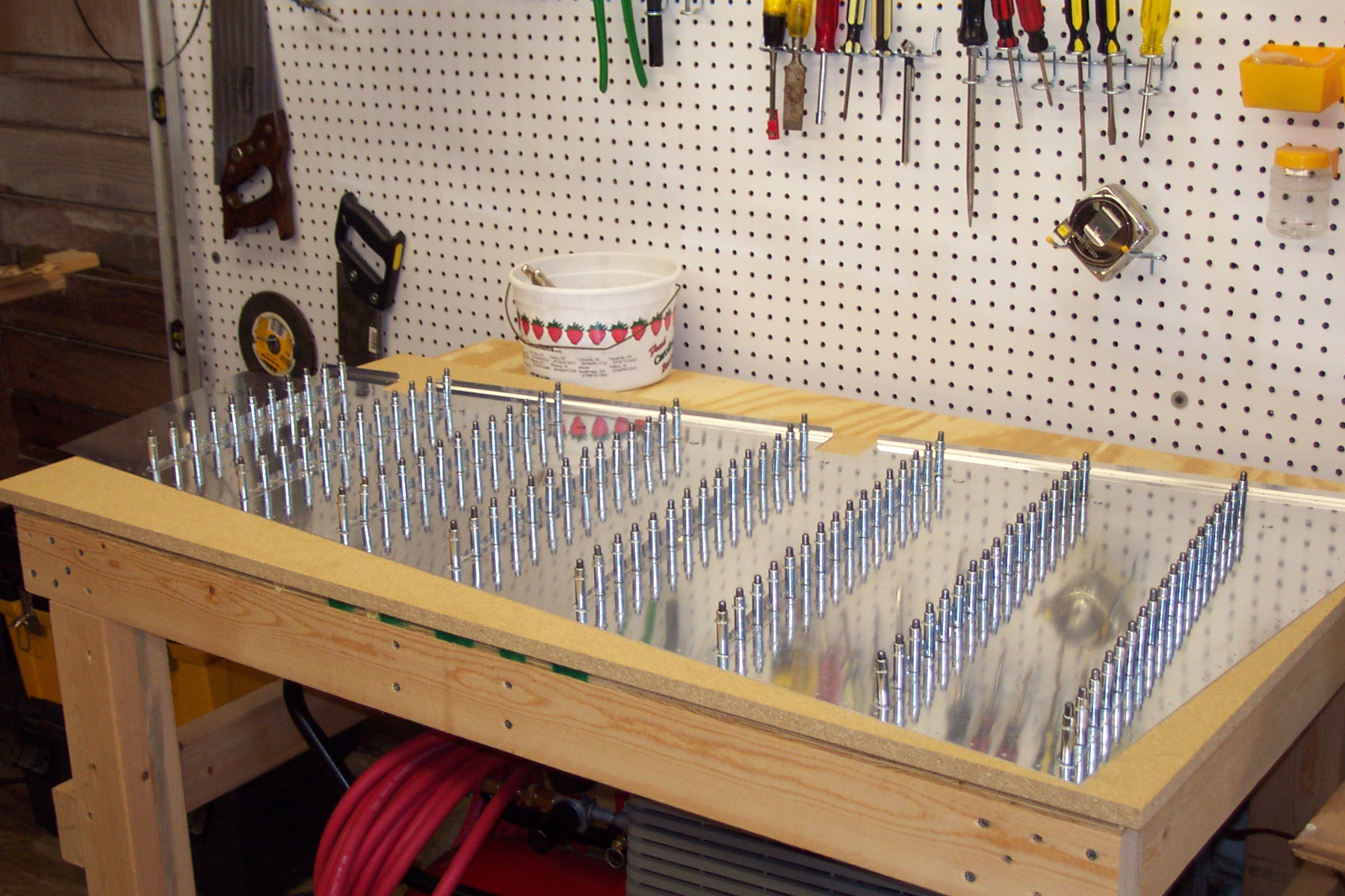
|
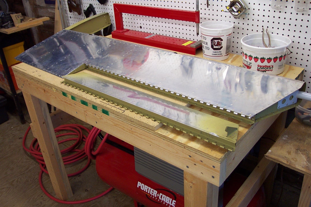
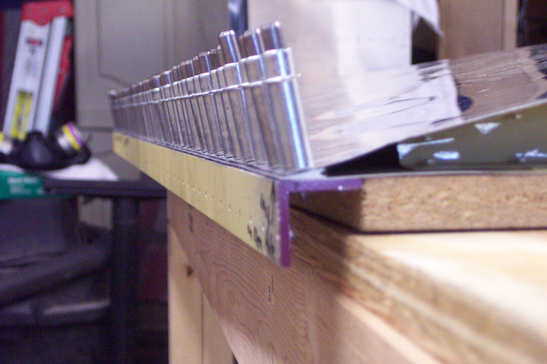
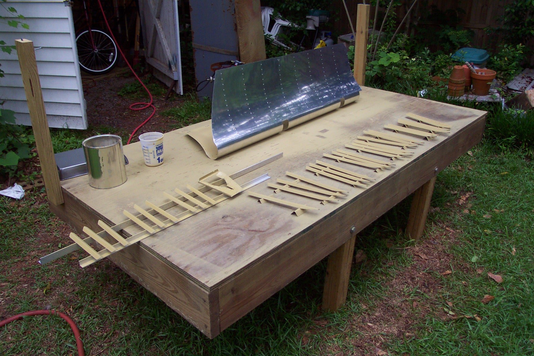
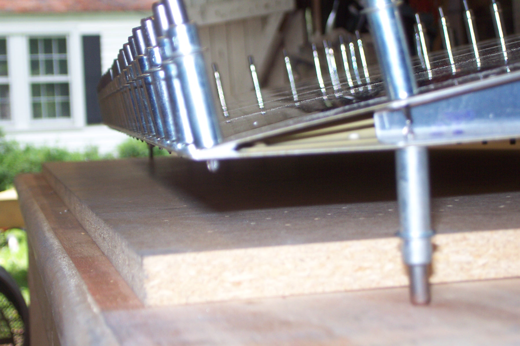
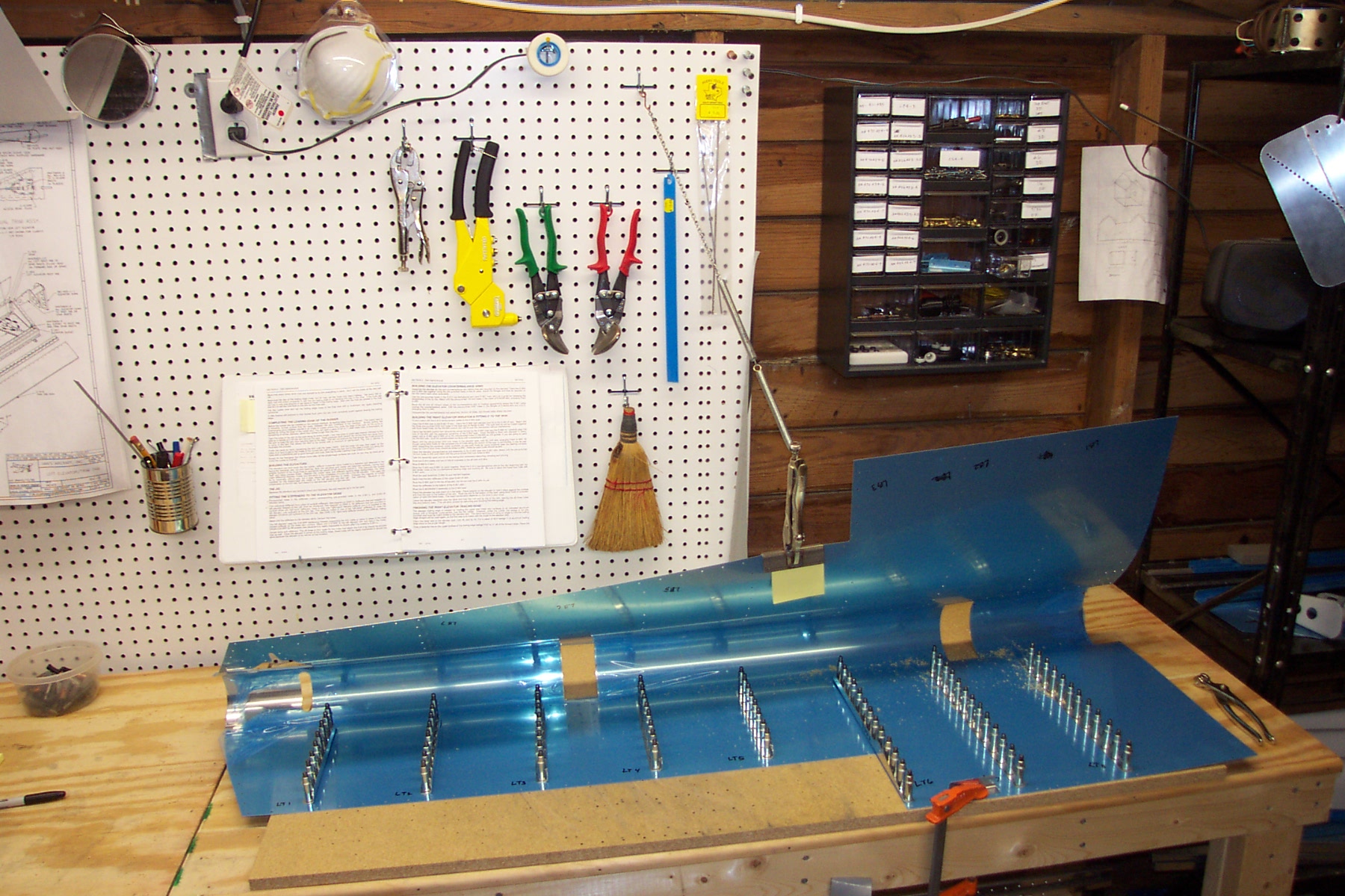
Match drilled the left elevator stiffeners to the skins. I had to figure out a better way to hold the skins open while I drilled. Here I clamped the skin to the table (right side of photo) with a piece of leftover stiffener metal between the clamp and the skin to protect it. I used a piece about two or three inches long to help spread the pressure of the clamp over a larger surface of the skin. I took two springs I had laying around and inserted the tightening screw of my hand seamer vice grips through the end of one of the springs. and attached the springs to a piece of chain I had laying around and that rig is hooked to my peg board. The hand seamer is clamped to the skin with some paper protecting both sides of the skin. I carefully lifted the skin up and pulled the chain/spring rig until the skin spread open enough for me to work with the drill and clecoes. This worked really well for me. I just made sure to be careful when opening the skins. The springs help take some of the pressure directly off the skin/seamers if you bump it. The springs came from an old "architect's" lamp I had thrown out years ago - I knew the springs would come in handy sometime! Yeh, right.
|
|
|
2003-03-29 |
Hours: 3.5 |
Category:
Empennage
|
|
Manual Ref:
6-6
|
ID#:
289
|
|
Trimmed elevator stiffeners and drilled on elevator skin |
|
Trimmed the elevator stiffeners and drilled them to the right elevator skin.
|
|
|
2003-03-25 |
Hours: 2 |
Category:
Empennage
|
|
Manual Ref:
6-4
|
ID#:
288
|
|
Drilled the stiffeners to the rudder skin |
|
Today I drilled the stiffeners to the rudder skins.
|
|
|
2003-03-24 |
Hours: 2.5 |
Category:
Empennage
|
|
Manual Ref:
6-4
|
ID#:
287
|
|
Trimmed the rudder stiffeners |
|
Trimmed and shortened all the rudder stiffeners.
|
|
|
2003-03-21 |
Hours: 3 |
Category:
Empennage
|
|
Manual Ref:
6-3
|
ID#:
285
|
|
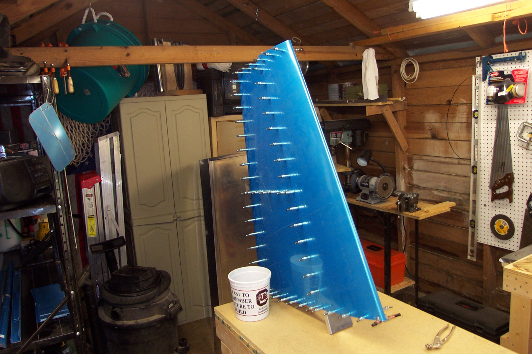
Assembled and drilled the vertical stabilizer |
|
Assembled and drilled the Vertical Stabilizer. Dimpled the HS & VS skins. This was quite a task, wrestling the skins into position on the dimpler. I mis-fired only one dimple and put a nasty dink mark in the skin, but I think I can cosmetically repair it when I finally get to painting the HS.
|
|
|
2003-03-14 |
Hours: 2 |
Category:
Empennage
|
|
Manual Ref:
6-2
|
ID#:
284
|
|
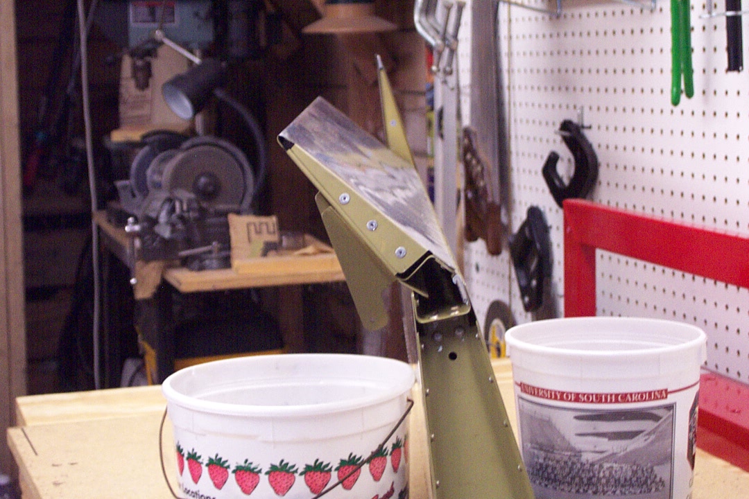
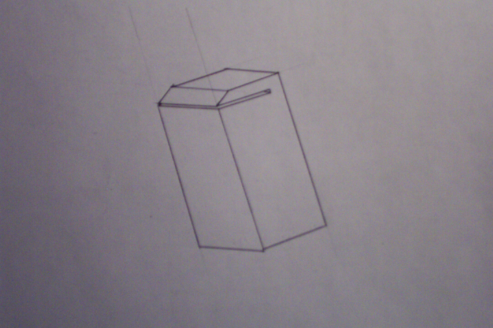
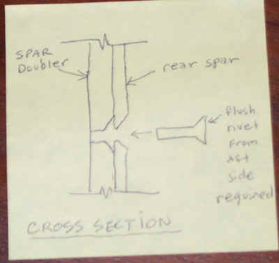
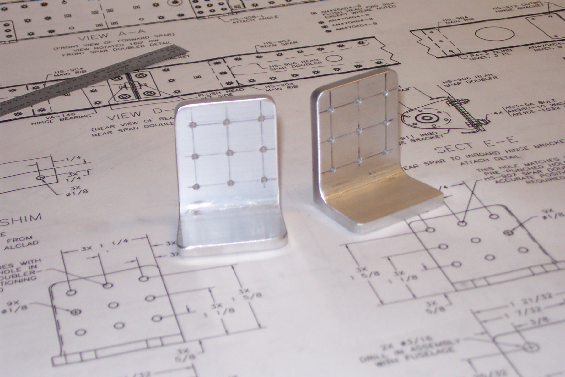
Countersunk the HS spars and doublers |
|
Countersunk the HS front and rear spars and the spar doublers. Ran into a problem with the rear spar doubler. The drawings and instructions are not clear when dealing with where to countersink the rear spar doubler. DWG 3, View D-D shows four holes to countersink. Two of these are to be in the forward side of the rear spar doubler and the other two (in the center) should be only countersunk in the aft side of the rear spar, not the doubler. The instructions where no clearer because they bother to tell you to "study DWG 3 carefully" but should simply warn you not to countersink the aft side of the doubler. Well, I got it wrong and contact Vans support@vansaircraft.com and receive a prompt reply as follows: "It is OK to just go ahead and set the rivet as you have prepared the holes. It's only two rivets and they get straddled by bolts later in the assembly. The strength won't be compromised. No need to make a filler." Here is a picture of a sketch I drew to show Vans what I did the countersinks incorrectly. Don't do it like I did! This refers only to the two center holes on View D-D that require countersinks. The other two outer holes do go in the doubler, but on the forward side.
|
|
|
2003-03-13 |
Hours: 2.5 |
Category:
Empennage
|
|
Manual Ref:
6-2
|
ID#:
283
|
|
Clecoed the right HS together |
|
Got the right HS clecoed together and all ready to drill.
|
|
|
2003-03-13 |
Hours: 2.5 |
Category:
Empennage
|
|
Manual Ref:
6-1
|
ID#:
282
|
|
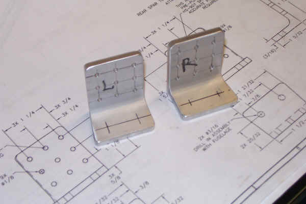
New attach angle material arrived from Vans |
|
Yesterday my expensive aluminum arrived from Van's. It cost about $5 but I am sure the shipping cost is much more. Plus Van's added a surprise handingly fee of $4. Ouch. Aren't FedEx boxes free? I ordered a 12" piece in case I messed up the attach angles again. I drilled the pilot hole in the top center of each angle and then clecoed them onto the forward spar/doubler and drilled the remaining eight holes thru the originally drilled holes in the spar/doubler. Everything looks great now! They are much better than the original ones I made earlier.
|
|
|
2003-03-11 |
Hours: 4 |
Category:
Empennage
|
|
Manual Ref:
6-2
|
ID#:
281
|
|
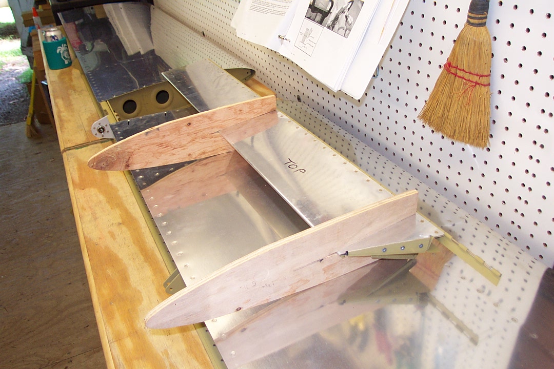
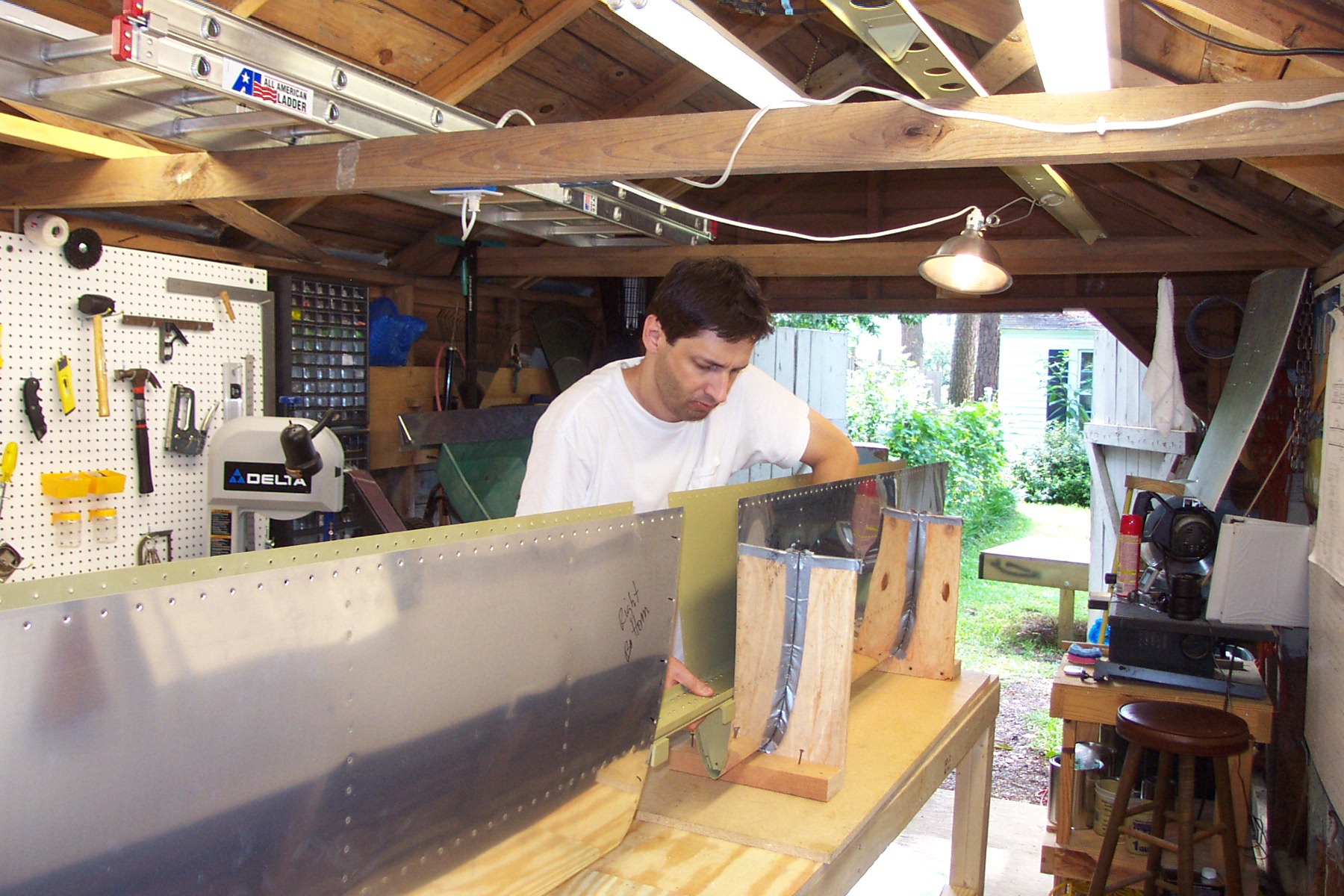
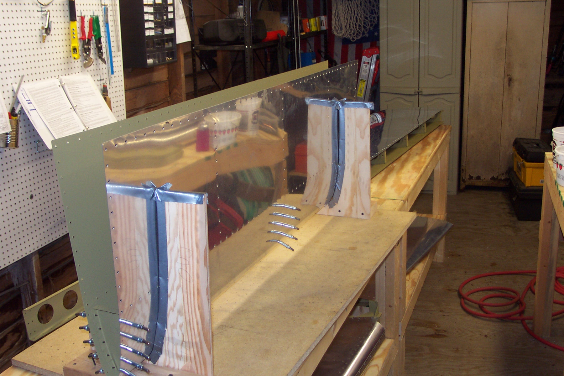
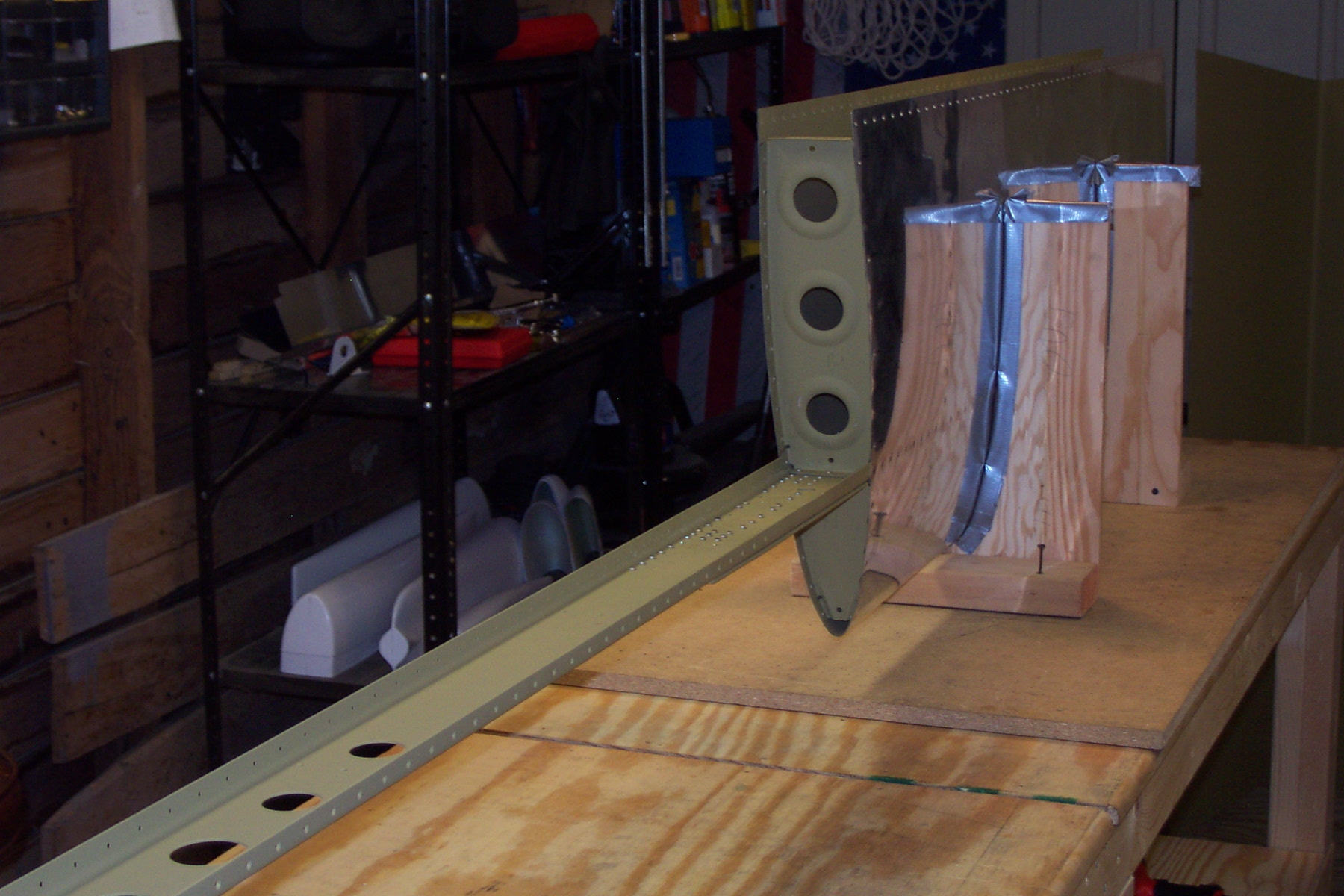
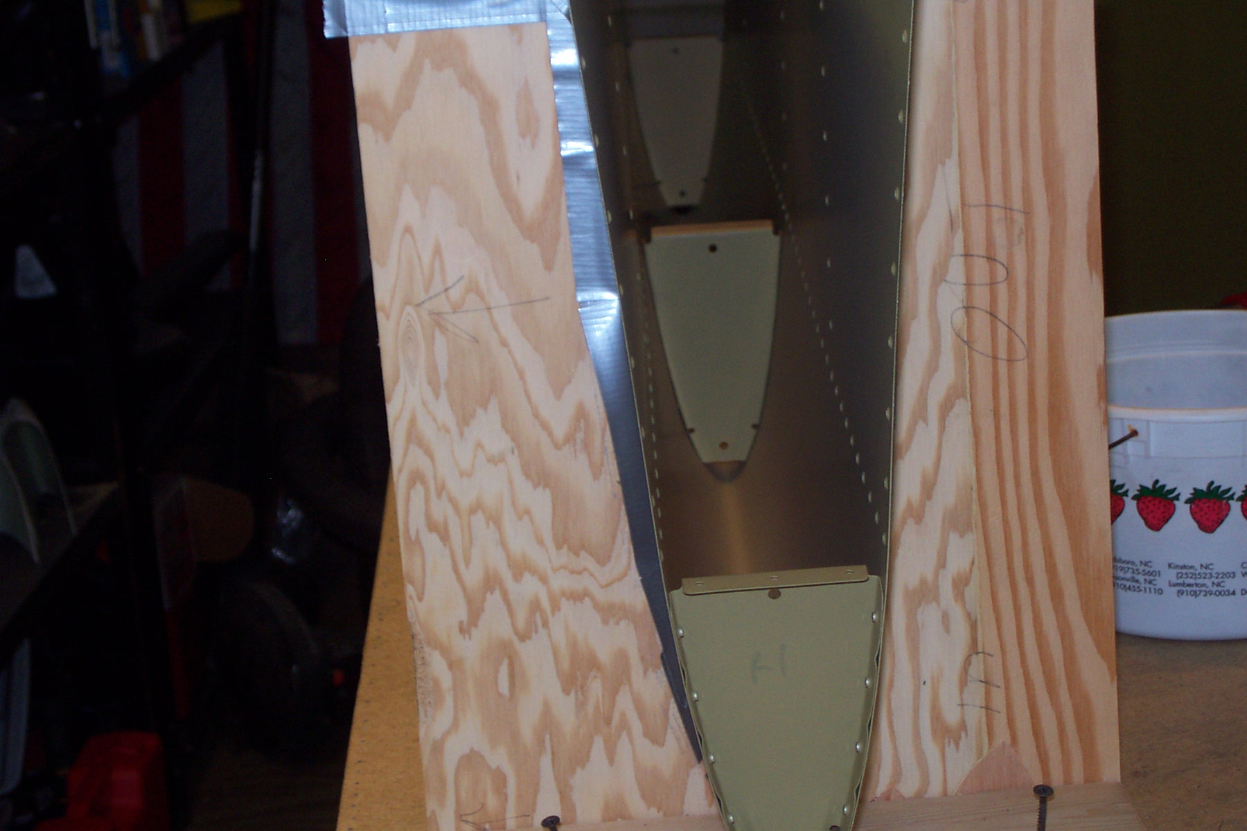
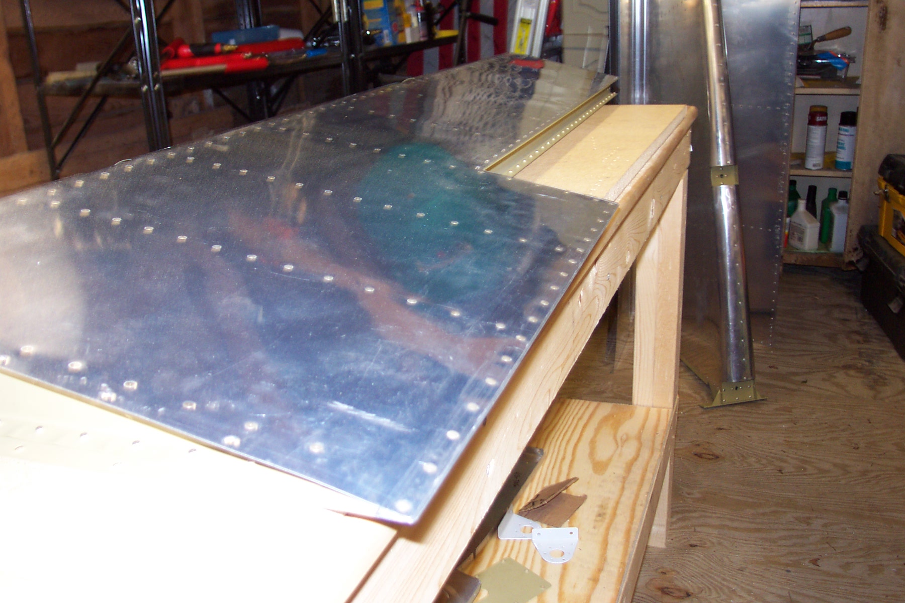
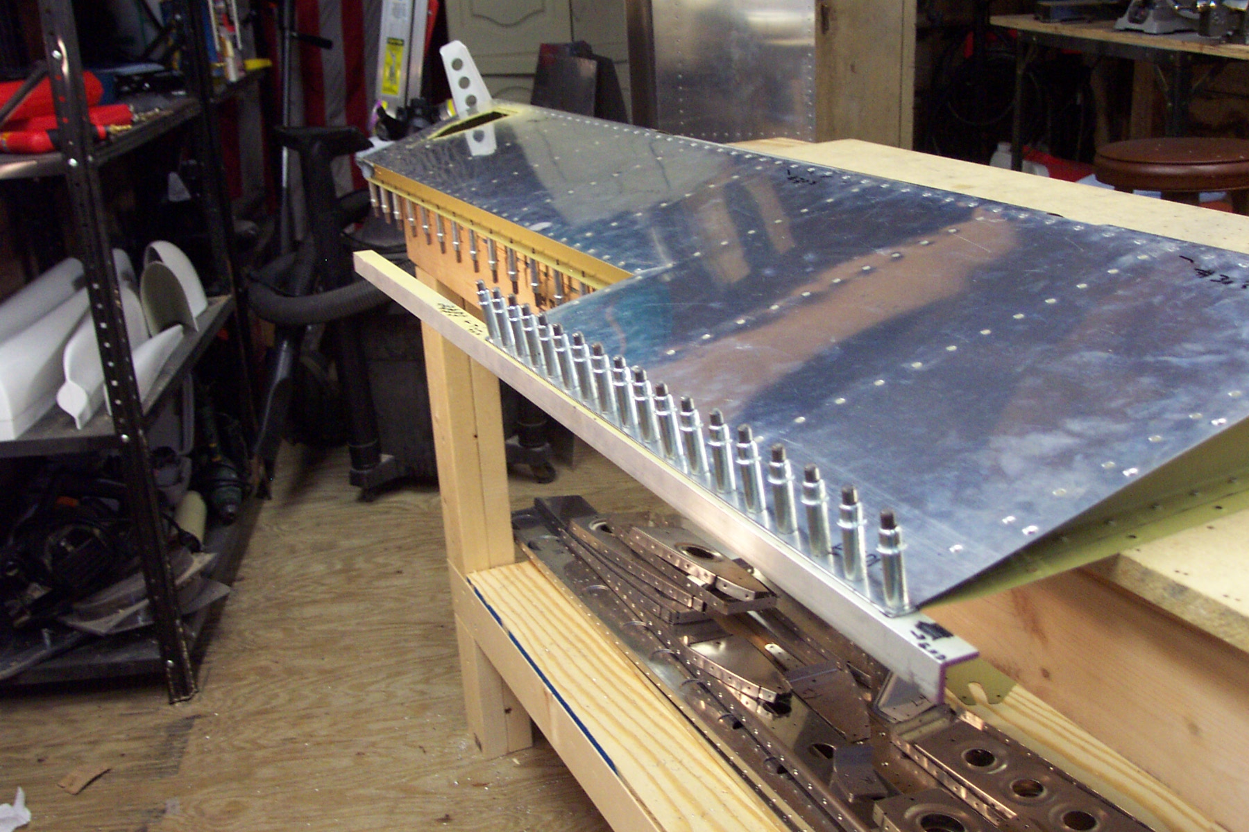
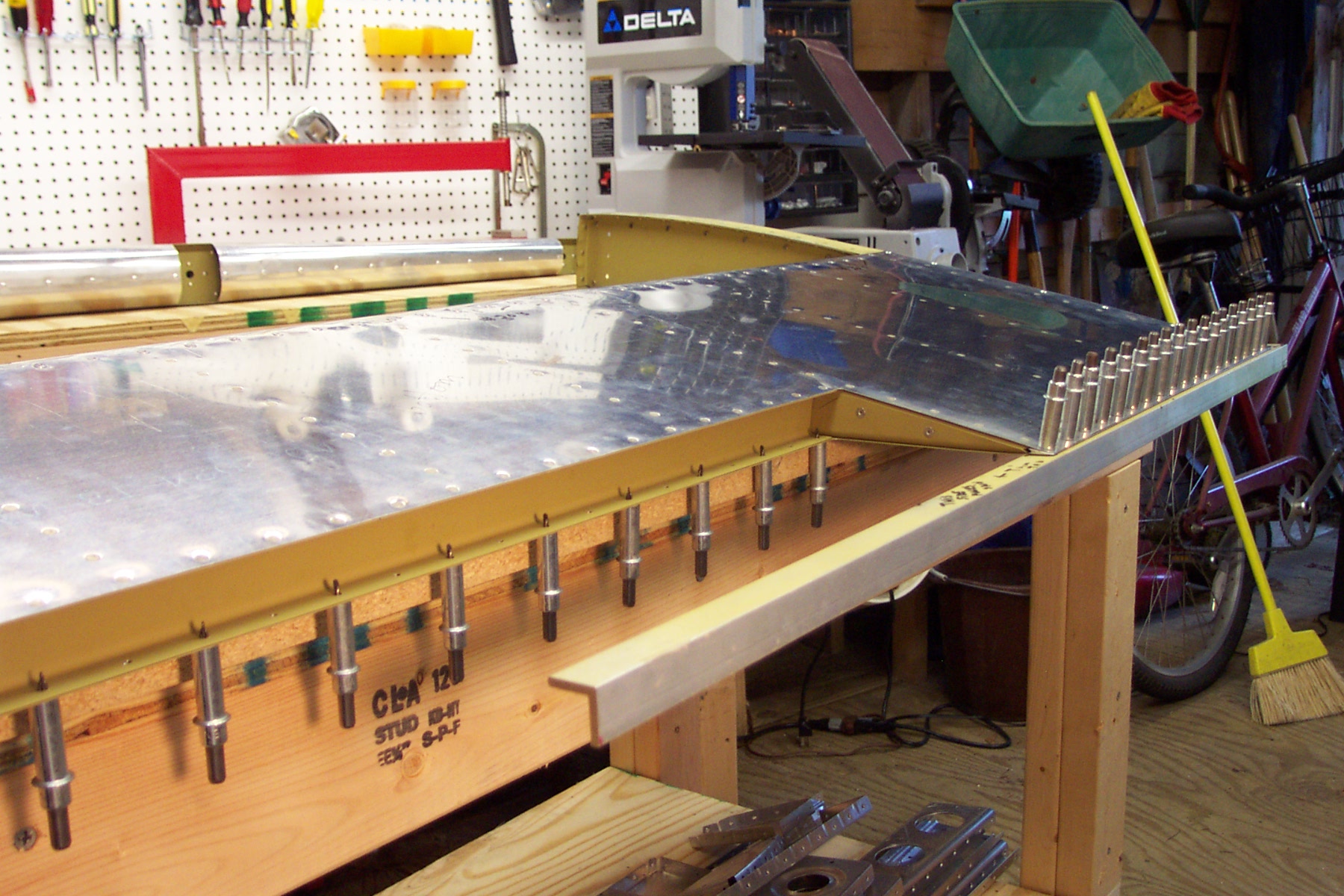
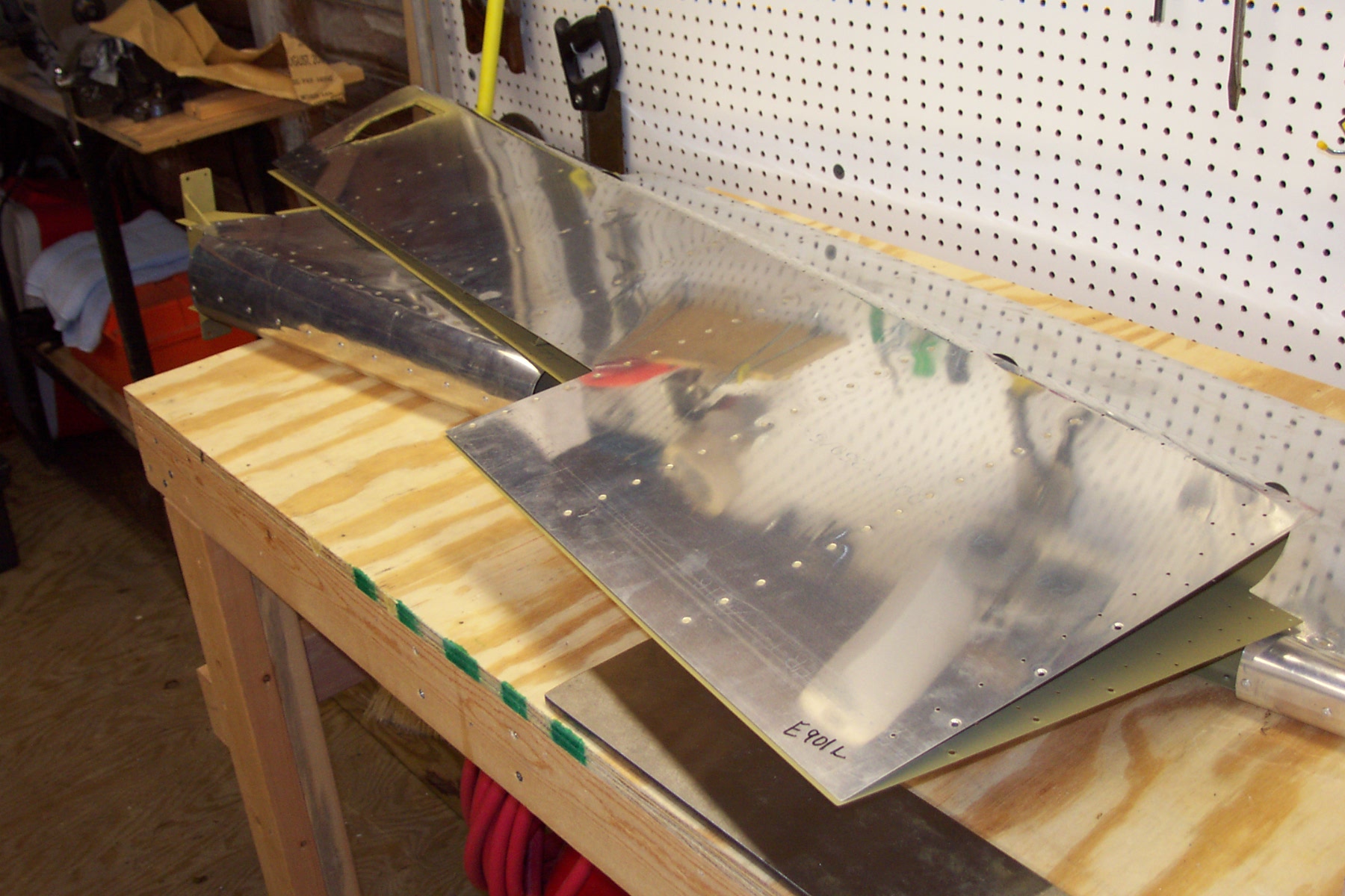
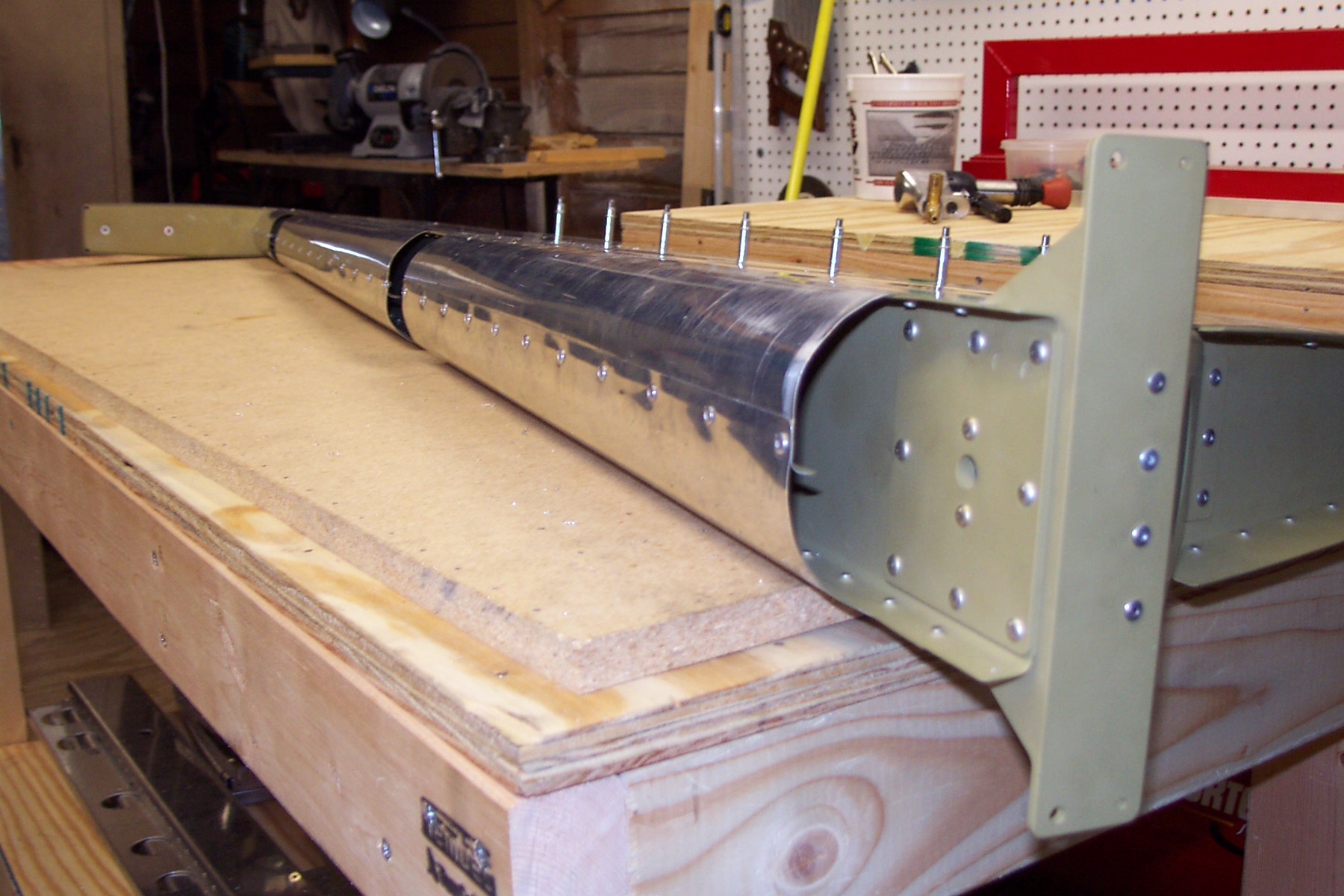
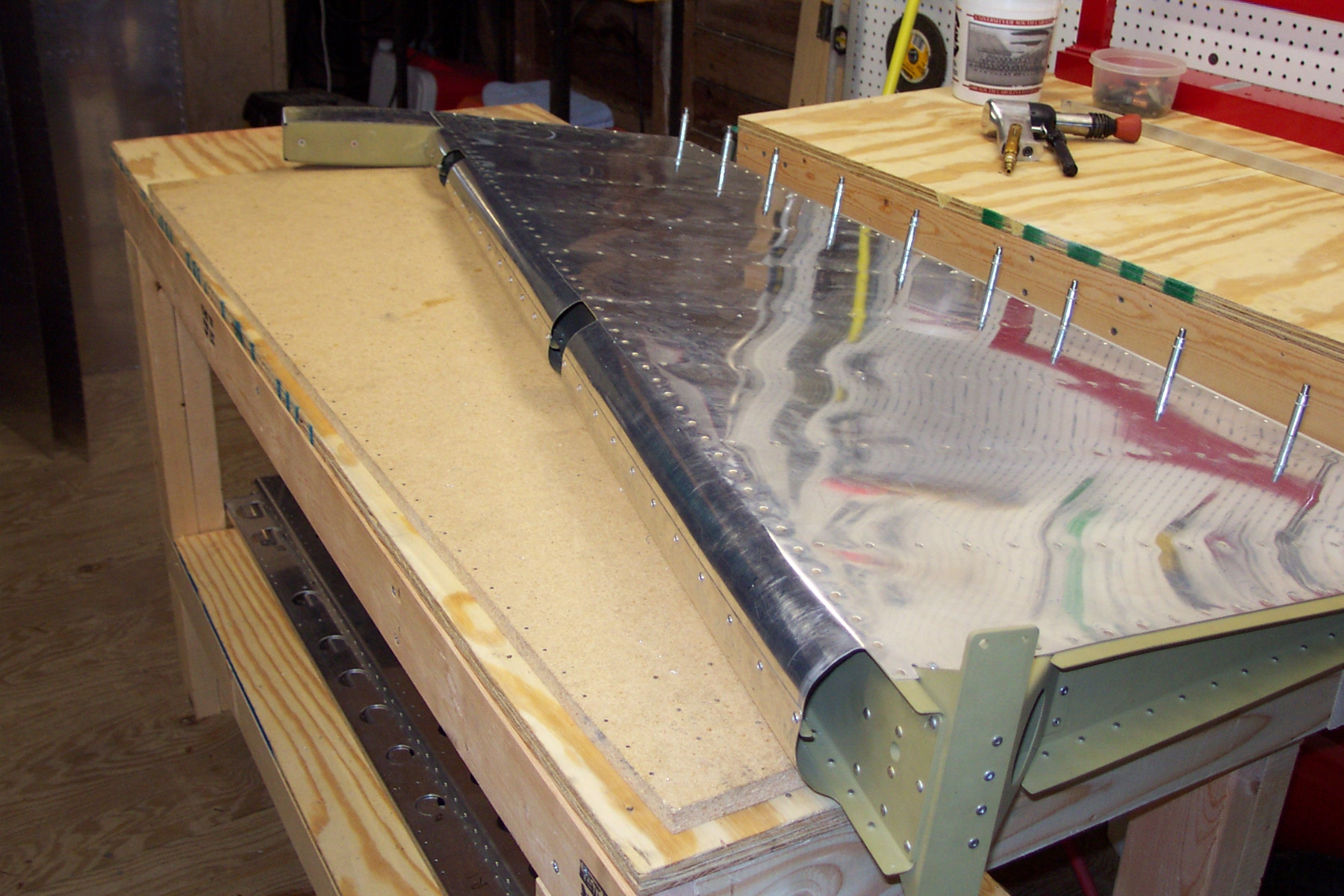
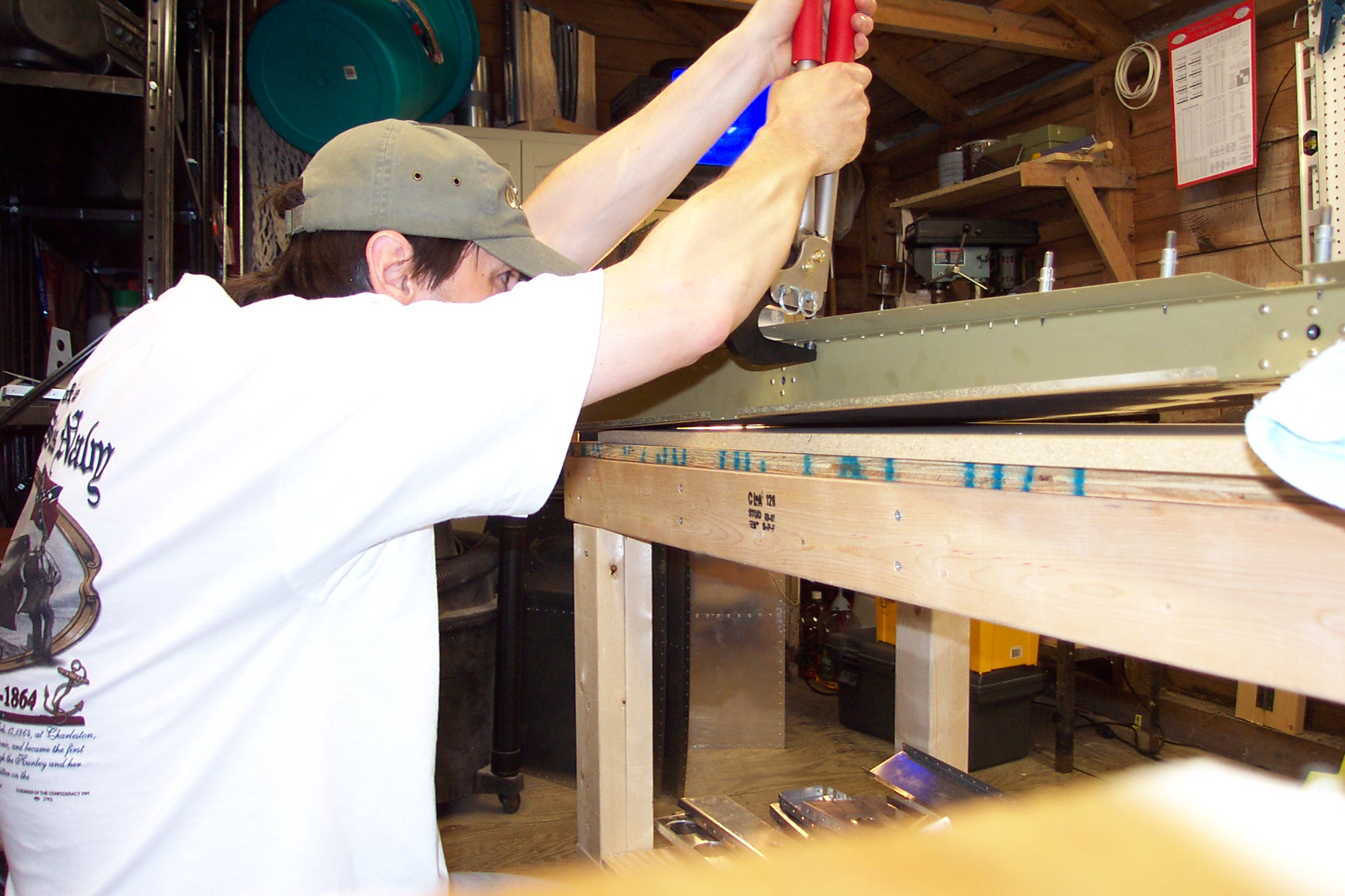
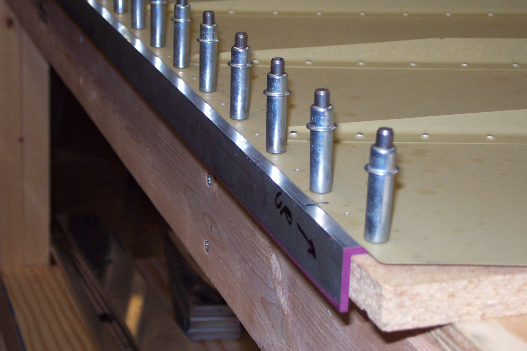
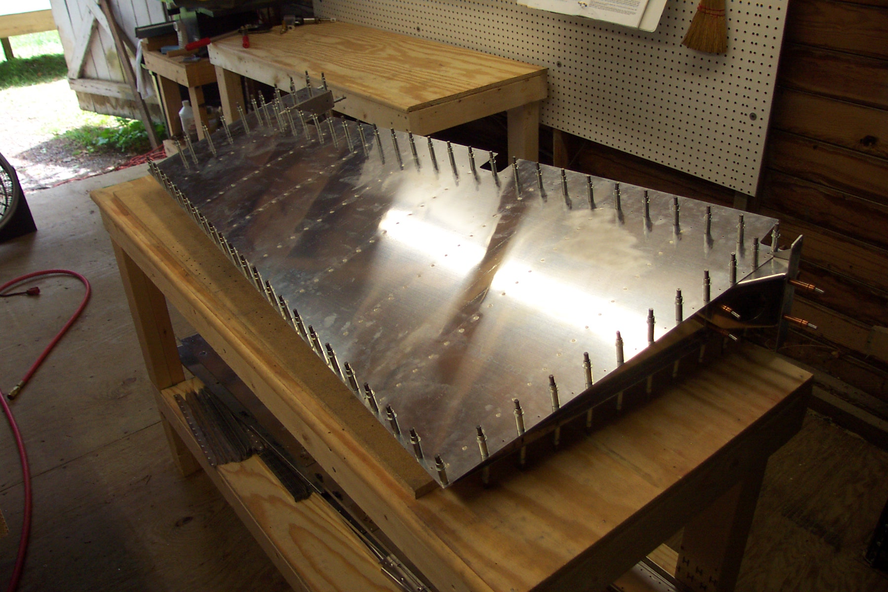
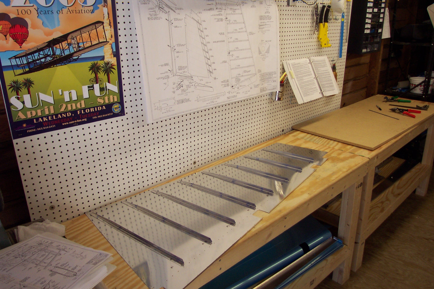
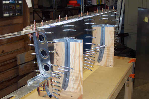
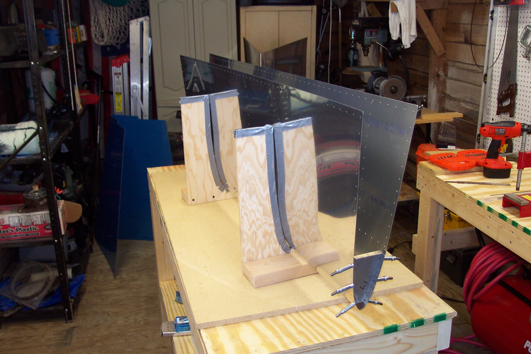
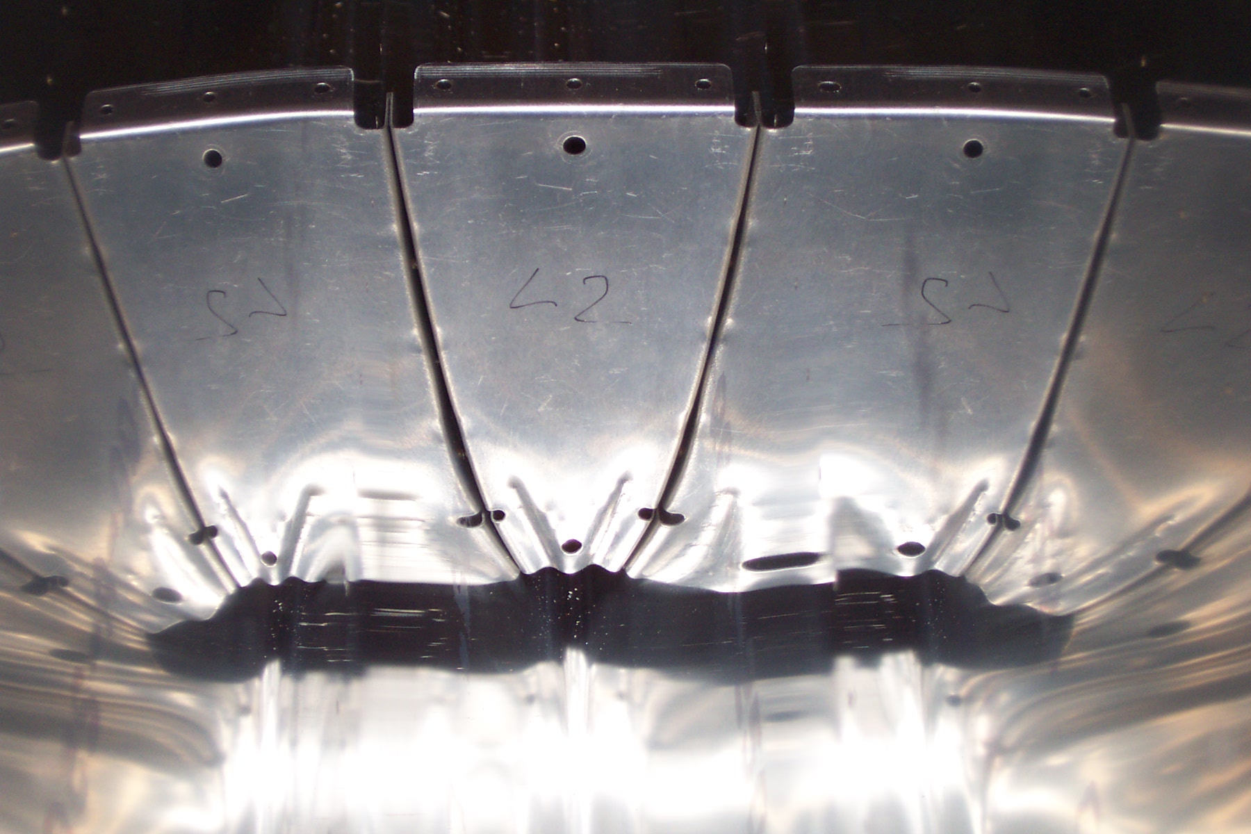
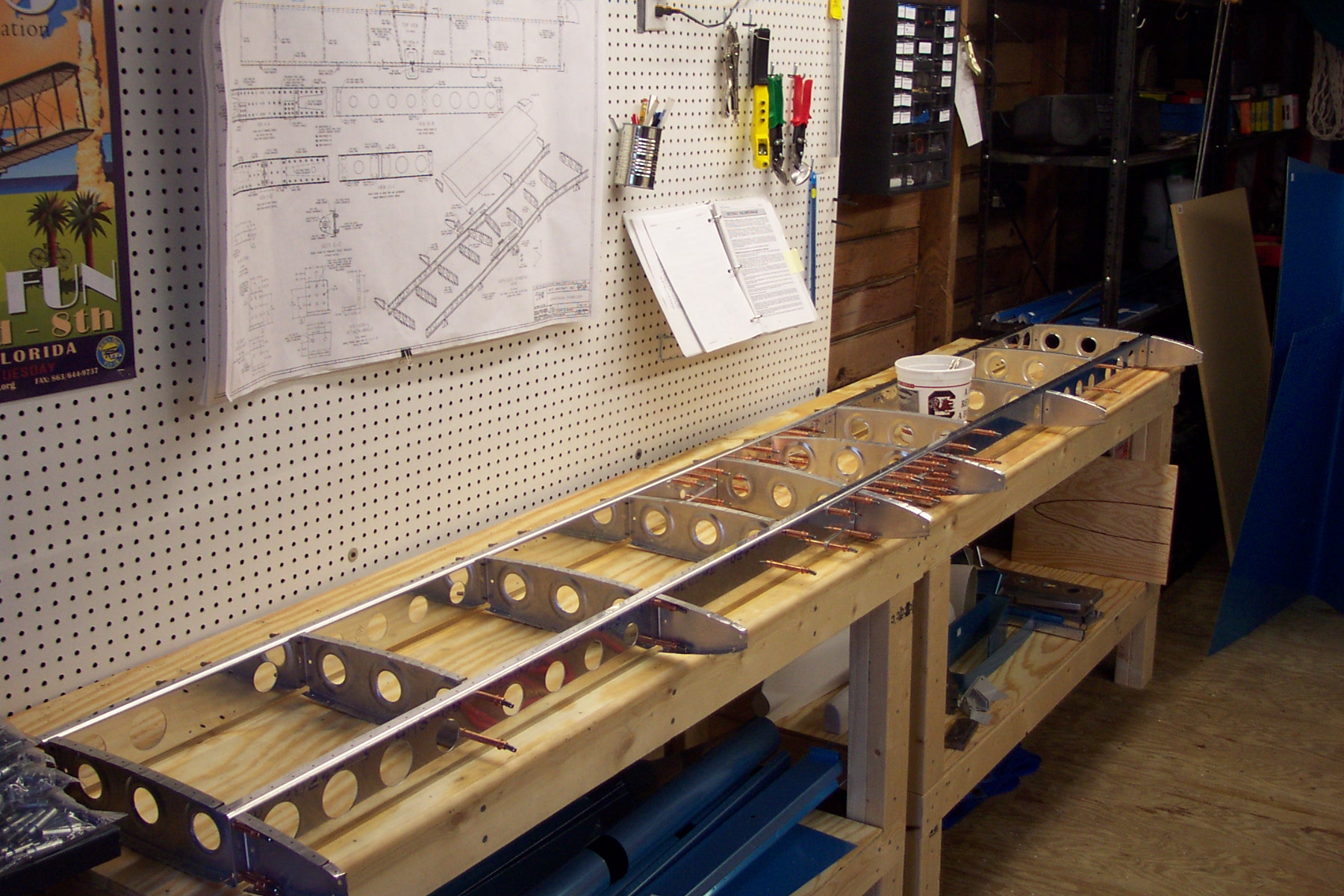
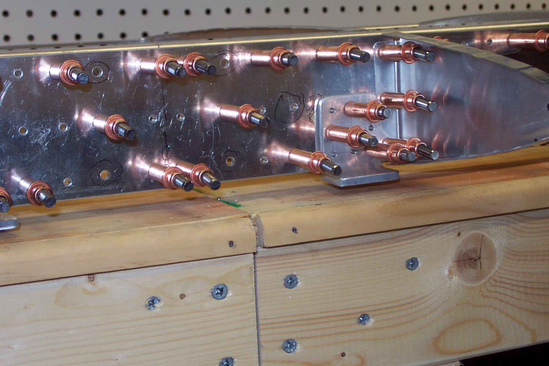
Mounted left HS skin into jigs and clecoed in the spars and ribs |
|
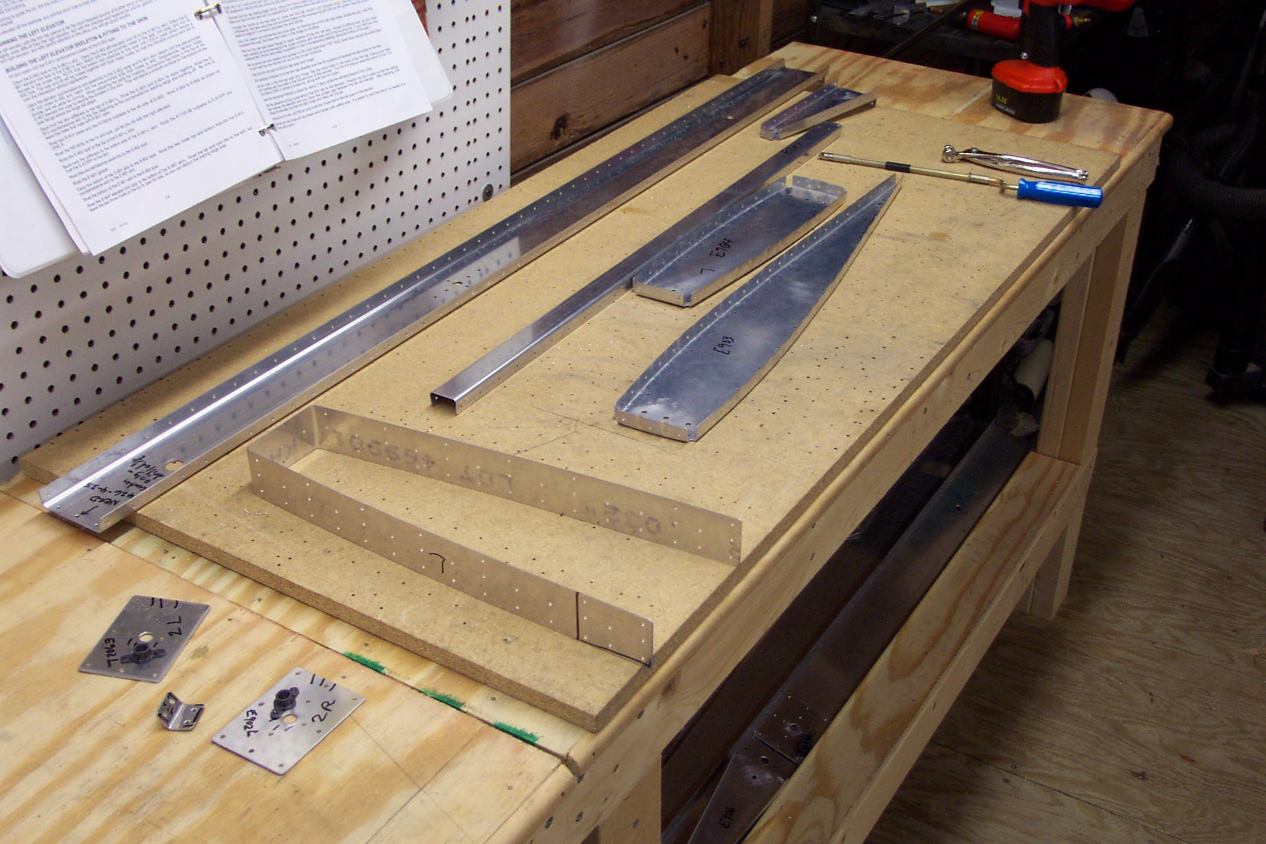
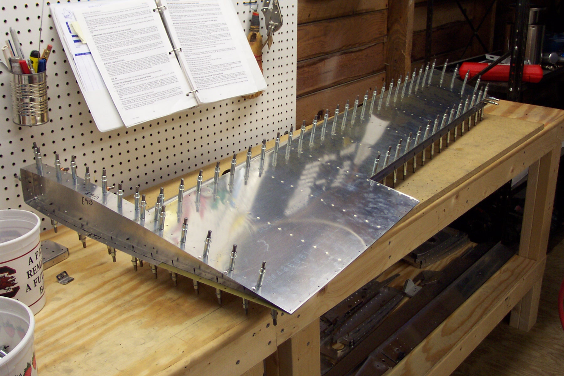
Mounted left HS skin into jigs and clecoed in the spars and ribs. Drilled all #40 holes, disassembled and deburred all #40 holes in the skin, spar and ribs. The nose ribs seem to fit nicely. I had to flute the forward end a good bit the make them fit into the skin and get the holes to line up properly. Note picture with nose rib marked "L2". This is the middle nose rib, optical illusion and all. Here I am concerned that there will be the "depression" in the top of the HS where other builders have had this problem. The rib and skin appears to fit okay, but I probably won't know for sure until I rivet the nose rib later on.
|
|
|
2003-03-09 |
Hours: 3.5 |
Category:
Empennage
|
|
Manual Ref:
|
ID#:
280
|
|
Ordered a new piece of angle from Van's. I clecoed the front spar, rear spar, main ribs, and nose ribs together. Drilled all #30 holes in the spars and ribs.
|
|
|
2003-03-08 |
Hours: 3 |
Category:
Empennage
|
|
Manual Ref:
6-1
|
ID#:
279
|
|
Started work on the emp kit |
|
Did some clecoing on the HS and manufactured the HS-908-L/R attach angles. I messed up and put the left attach angle on the right side of the HS spar and vice versa. I match drilled the remaining eight holes in each angle with the spar on each angle and realized they were switched. Shoot! I tried to see if I could switch them but the holes do not line up. Close but no good. I will order another piece of angle from Van's and make new attach angles.
|
|
|
2003-03-08 |
Hours: 2 |
Category:
Empennage
|
|
Manual Ref:
|
ID#:
278
|
|
Inventoried - all parts accounted for except a bearing package marked on the list as back-ordered.
|
|
|
2003-03-06 |
Hours: 0.5 |
Category:
Empennage
|
|
Manual Ref:
|
ID#:
277
|
|
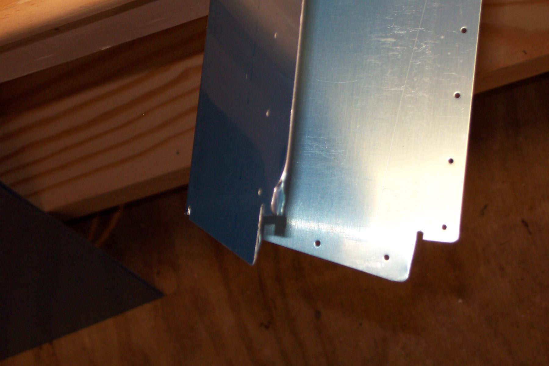
A quick survey of the larger parts revealed only two bent edges. I tried to straighten them out as best I could. I think they are a minor concern that will not effect structural integrity. I'll contact Van's to see what they think. The first picture is of the damage to the elevator trim. The second picture shows the bent area on one of the elevators at the trailing edge.
|
|
|
2003-03-05 |
Hours: 0.25 |
Category:
Empennage
|
|
Manual Ref:
|
ID#:
276
|
|
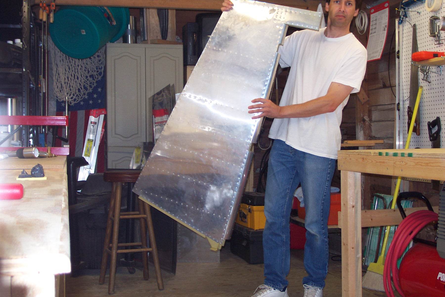
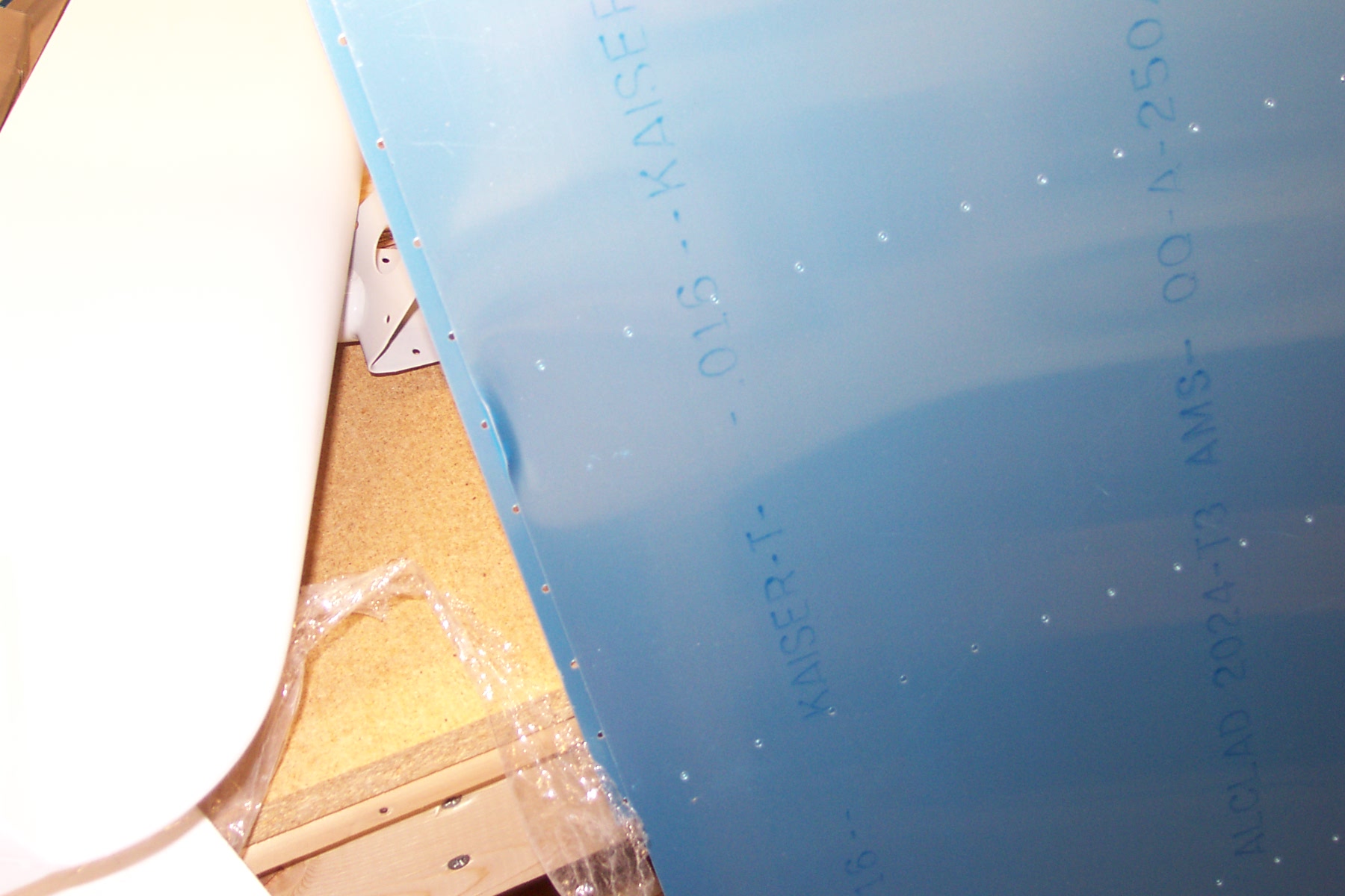
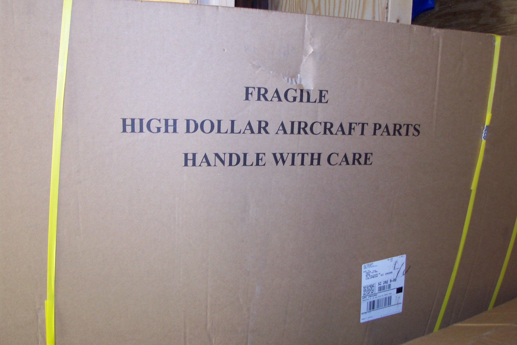
My Empennage kit arrived today! |
|
I am finally somebody - Van's #90709! Note big gash in the large box right above the word "Fragile." Got to love those delivery people!
|
|
|
2003-02-13 |
Hours: 0 |
Category:
Empennage
|
|
Manual Ref:
|
ID#:
274
|
|
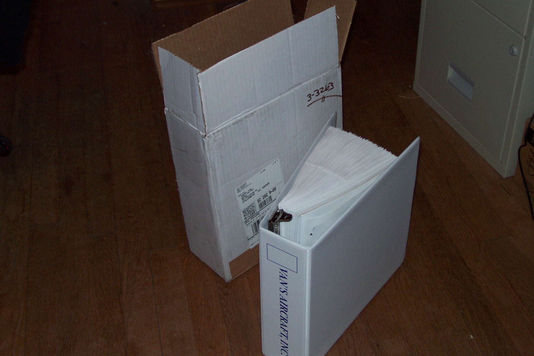
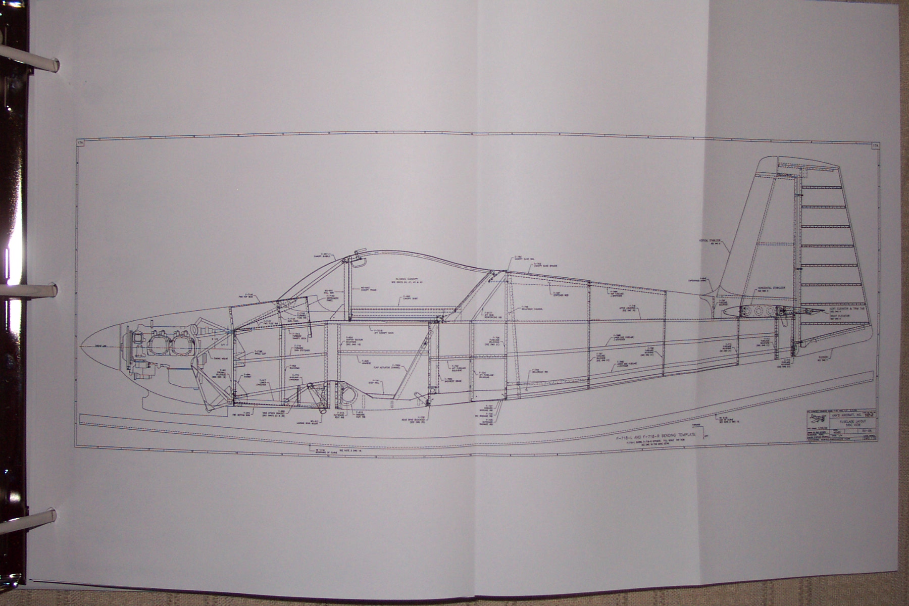
Preview plans arrived today! |
|
My Preview Plans arrived. I can't wait for the Emp kit to get here. I need to be riveting as soon as possible.
|
|
|
|
|